I don't know of any way to test these beyond trying them in a functional circuit. If the chip is good then the oscillator should be running and you would pick that up on the resonator. They are generally very reliable and were extensively used in much commercial gear as system clocks and so on. Most problems were with the two legged variety where a lead would physically fracture and break. That was a number failure mode in remote handsets.
Depending on the frequency a USB scope might be way out of its depth.
Depending on the frequency a USB scope might be way out of its depth.
With the chip in place you check with the oscilloscope to see if there is oscillation on the two pins going to teh chip.
You want to use 10x mode on the probe (1x will guarantee no oscillation as it'll disturb the circuit too much), have the ground clip connect as to the middle pin (or the wavefom is going to get distorted) and tip to either of the edge ones (one is input, one is output and they usually show slightly different waveform level). You may have to zoom in quite a bit horizontally, depending on what the expected frequency is, 4MHz is 250ns so you probably want to get close to this to see a clean waveform with the scope. You cannot test the part as is without the oscillator circuit inside the chip itself (pierce oscillator most typically).
You want to use 10x mode on the probe (1x will guarantee no oscillation as it'll disturb the circuit too much), have the ground clip connect as to the middle pin (or the wavefom is going to get distorted) and tip to either of the edge ones (one is input, one is output and they usually show slightly different waveform level). You may have to zoom in quite a bit horizontally, depending on what the expected frequency is, 4MHz is 250ns so you probably want to get close to this to see a clean waveform with the scope. You cannot test the part as is without the oscillator circuit inside the chip itself (pierce oscillator most typically).

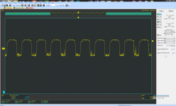
You have to set your timebase to much faster(it is at between 10ms...100ms, it needs to be at 100ns), since it is a digital scope it will be aliasing like crazy with such slow timebase + such fast signal.
The oscillator is definitely doing something so it is probably not the problem, but you got to zoom in first to verify it is at roughly 4MHz. Right now you're seeing artifacts pretty much.
The oscillator is definitely doing something so it is probably not the problem, but you got to zoom in first to verify it is at roughly 4MHz. Right now you're seeing artifacts pretty much.
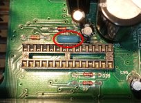
I would have thought the middle pin was ground. AFAIK the three terminal resonators simply include the two tiny caps needed to form an oscillator while the two pin ones do not.If I need to get to the middle pin it will require complete disassembly.
Lots of 50Hz suggests a ground problem somewhere (floating). Make sure the scope probe is grounded correctly (I would say to the ground that the centre pin goes to) and recheck. You also need to look at the spec of the scope as you need at least a bandwidth of 4Mhz and preferably a lot more. You should see a nice sine at 4Mhz.
Scope has a range of 20Mhz.
At 100ns setting it's a complete mess.
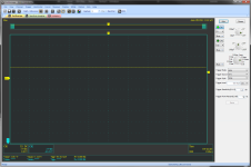
I disassembled the amp. The middle pim is ground, but I don't read anything on pin 1 and 3 to ground (with x10 probe too). My previous measurement that showed 50Hz I did between pin 1 and 3 (not to ground) which is clearly incorrect.
Power supply is good - Vpp90mV
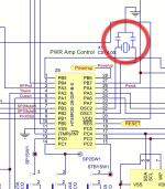
@BSST: maybe you mean pin 22 - OSC2
At 100ns setting it's a complete mess.
I disassembled the amp. The middle pim is ground, but I don't read anything on pin 1 and 3 to ground (with x10 probe too). My previous measurement that showed 50Hz I did between pin 1 and 3 (not to ground) which is clearly incorrect.
Power supply is good - Vpp90mV
@BSST: maybe you mean pin 22 - OSC2
Attachments

If you suspect the resonator then you could try it in a test circuit using a CMOS chip (invertor, NAND gates, whatever you have). Last image here. Standard generic oscillator circuit. Remember the three pin resonator has the caps built in and connected to the centre pin.
https://www.qsl.net/yo5ofh/doc/ceramic_filters/ceramic_filters_and_resonator.htm
One side of the resonator goes to the input of the gate and the output drives the other end of the resonator. The output end should be more squarewave looking usually. This is all that will be inside your chip to form the oscillator.
Generic circuit.
The main suspect is the chip which is impossible to find (Arcam Alpha 10) but there is little hope that the problem is in the resonator.
If it is confirmed that the problem is in the chip I had read somewhere that the amplifier can be modified to work as Power Amp.
Is it possible in your opinion?
If it is confirmed that the problem is in the chip I had read somewhere that the amplifier can be modified to work as Power Amp.
Is it possible in your opinion?
It might be worth checking out the power supplies before deeming the processor faulty. This is around the vintage where electrolytic caps start failing. If the supplies are dirty to the processor they might not operate.
Haven't looked at the circuit but I would say almost certainly possible and probably very easy to do.If it is confirmed that the problem is in the chip I had read somewhere that the amplifier can be modified to work as Power Amp.
Is it possible in your opinion?
Probably a failed processor, but some last-hope checks of oscillator active stage:
1: OSC2 should be mid-supply if active stage is viable and resonator is not shorted.
2: Short OSC1 to ground. OSC2 should show about +5V.
3: Short OSC1 to +5V. OSC2 should read about 0V.
If active stage proves viable, maybe all's needed is a new resonator.
1: OSC2 should be mid-supply if active stage is viable and resonator is not shorted.
2: Short OSC1 to ground. OSC2 should show about +5V.
3: Short OSC1 to +5V. OSC2 should read about 0V.
If active stage proves viable, maybe all's needed is a new resonator.
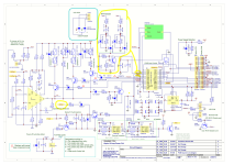
The 22pF couplings shows that part of the circuit must be looking for very high frequency oscillation on the output. I've never seen anything like that included on an amp before. So yes, it can be ignored although you have to wonder why they included it in the first place. Did they expect it to burst into oscillation and destroy tweeters or do they think someone might try and use it as an RF power amp 😱What is "RF Protection"? Can it be ignored?'
The RF protection will mute the amp when an RF signal hits the inputs I think, preventing high volume RF breakthrough from damaging your speakers and ears! Basically mobile phones or nearby radio taxi are the threats addressed. The circuit is just a pair of RF detectors.
Another question arose about turning it into a power amp. Can I ignore the ACDet (seen in the schematic in a previous post)?
All you need to create a power amp are the audio inputs, the speaker outputs and a functional relay delay. AC detect will be used to mute and/or drop the relay out as soon as the mains disappears.
If parts of that circuitry are non functional then just add a separate relay and DC offset protection board.
If parts of that circuitry are non functional then just add a separate relay and DC offset protection board.
- Home
- Amplifiers
- Solid State
- How to check ceramic resonator?