For Sale Elsinore MK 6 NRX in Germany

Hello,
here I like to offer my first attempt to construct the Elsinore speakers, a pair of MK6 with the NRX speakers and the coresponding crossover.
I build a second pair with the Purify speakers. Both have there personal character, but with a front of Panzersperrholz the second attempt suits more my taste.
The pair I offer is made of medium density chipboard (internal, front and back), the corpus made of beech multiplex.
Front and back show olive veneer, the colour is silver gray, obviously easy to change.
The finih is not perfect, I struggled a little bit with the veneer. But for an amateur I guess they are more than okay,
The socket is 25 cm high and contains the crossover.

I guess it is not neccessary to describe the sound, they are for sure extremly good and naturally sounding, imaging is extraordinary..

Actually I use these speakers in a 23 m² room with very good succes, the first room I used them in the past shows about 60 m².

Due to private circumstances, I am going to loose the 60 m², split with my friend, so I have one spare pair of Elsinores.

They are big, they are heavy, I didn't weight them, but I guess more than 50 kg each speaker.

I like to ask 950 €, a bargain looking on the 1700 € material and 100 hours of time I invest. You will surely find no speaker with a similar pricetag sounding nearly that good.

A grain of salt, only for someone who is able to pick them up at my home in Nuremberg, a good opportunity for listening to them.

If you won't listen to them at my home I am willing to help with the transport, my car has sufficient space. So this is debatable.

Attachments

  • Els 2.jpg
    Els 2.jpg
    176.3 KB · Views: 237
  • Els Rück.jpg
    Els Rück.jpg
    140.1 KB · Views: 213
  • Els Weiche.jpg
    Els Weiche.jpg
    432.6 KB · Views: 234
  • Elsinore NRX.jpg
    Elsinore NRX.jpg
    172 KB · Views: 263
  • Like
Reactions: 32y0

Help with Buzz Noise

Hello Everyone,

I'm having some buzz noise issues from my power amp just out of the blue, and need some advice to solve this.

The problem may be from the TIP31 transistor at the driver stage.
When I use my fingers to hold the casing of the transistor, the buzz noise greatly reduced to almost not audible (still there unless I place my ear right next to the speaker driver), but once I let go, the buzz noise comes back.
This problem happens to both channels.
The buzz noise stays at the same level even when I turn the volume to max, and don't seem to be bad soldering as the amp still plays apart from the buzz noise.

The complementary TIP32 don’t seem the have the same issue.

Anyone had similar problem before?

Volume Control with Loudness and no Taps

Hi! Anyone have schematic for passive volume control with loudness compensation and 250-500K potentiometer without taps? Tapped pots are very problematic to obtain today unless ordered in quantity 100+ directly from factory.

I found schematic on Steve Bench web site (attached to this post), but I have no idea of its origin. In the books I have there are schematics, but ALL use tapped potentiometers.

Thanks in advance for any suggestion(s).

Attachments

  • loudness_compensation_circuit.gif
    loudness_compensation_circuit.gif
    2.7 KB · Views: 2,076

Fosgate 600 4 channel

After repairing my bd1000 with Perry’s help and finding it fun I decided to get a few broke amps on eBay and give them a go. 600.4 board 3085-a

Broke rcas replaced. Played audio at this point but only tested for a few seconds. One buz fet was physically chipped. Replaced all outputs with 540/9540’s. Replaced all source resistors as a few looked burnt. Set bias using 50ma increase method per channel. Idles at 1.2a (1.0a with all pots fully ccw)

Amp plays across all channels individually at low volumes. When testing it drew about 2-3a. It will randomly cut out for 1-2 min and come back on its own. Power light stays on. Rail-rail voltage drops to 20v. Input power drops to 0.5a. Once I cycled the remote off/on and it came back to its failed state. While probing my hand slipped and ended up burning 2 psu fets on same side.

With the blown irf1010e cut out I limped the amp along to see if I could get it to cut out again. It happened once or twice then eventually not at all. By now the amp is warm. Maybe the warmer it is the less likely it will cut out? Or the fets that burnt were part of the cut out issue too.

I’m going to replace all 3 psu fets on the burnt side and probably the other side as well. Maybe when it cools overnight it will cutout for longer to give me a chance to poke around more.

Is there a likely cause? What can cause rail voltages to drop, and stay symmetric, without excess current draw ?

Hornresp manual

Here is a small hornresp manual. If you can now use it, just download it. Unfortunately, it is translated from Swedish with google translate so there may be errors due to the translation. There is also an error on page 23 the image in the middle should not be included.

Attachments

Conversion from Level Dependent to Level Independent Loudness Effect - what Rules ?

First a merry christmas weekend for everyone.

Mostly usual in integrated amplifiers is a level dependent loudness effect - for this an attenuator with tap in the first third or quarter of a 270 degree potentiometers is necessary - go to
https://vajacases46-com.myshopify.com/products/radioshack-100k-dual-ganged-stereo-volume-control
and
Using tap potentiometer loudness circuit under Meter Counter Circuits -60631- : Next.gr

But there are to accept two great disadvantages:
1) If there are low level or very high level input sources at the integrated amplifier, there is no possibility of moving this tap, i. e., the effect of the midrange attenuation is too weak or too strong.
2) If there is necessary the replacing of that pot, no genuine part is available (except an identical amp model is present for spare parts), i. e. with usual three-pin pot the loudness option isn't longer available.

By checking some service manuals of integrated amplifiers for a helpful solution, I note, that Luxman's R5030 used at least an additional loudness potentiometer for adjusting resp. for the stepless setting of the loudness effect resp. the midrange attenuation - go to page 15 under
LUXMAN R-5030 SM Service Manual download, schematics, eeprom, repair info for electronics experts
Yamaha's AX-570 does the same, but without a tap on the volume attenuator resp. volume control pot - go to
YAMAHA AX-570 SM Service Manual download, schematics, eeprom, repair info for electronics experts
and
https://web.archive.org/web/20210623113458/https://www.schematicsforfree.com/archive/file/Audio/Circuits/Equalizers, Filters & Tone Controls/Loudness Controls/APEX Loudness Control.jpg
Unfortunately the loudness characteristic resp. the individual cut-off frequencies are different at all brands - each manufacturer use his own concept therefore.

After the long preface, now the question:

Which details do I have to pay attention to when converting the level dependent loudness circuit from Luxman's L190 - go to
LUXMAN L-190A Service Manual download, schematics, eeprom, repair info for electronics experts
to level independent loudness like from Yamaha's AX-570 while maintaining of the characteristic resp. the individual cut-off frequencies for the attenuated midrange of Luxman's L190 ?

If I know this, I order a usual pot without tap for loudness and I would then use the balance control potentiometer for the loudness control, because the balance control isn't absolutely necessary by the currently user.

Thank you very much for an advice and appropriate links.

Level-dependent loudness approaches

switched version - one position (loudness on/off) increasing low and high frequency area at low volume level - 4-pin (tapped) pot in use

https://www.extron.de/article/loudnesscontrol_ts
https://www.extron.com/article/loudnesscontrol_ts
http://kit-amp.com/alps-rk27-volume-control-loudness-en
https://www.eevblog.com/forum/repair/loudness-tap-in-old-audio-potentiometers/ (reply #8)
https://www.angelfire.com/electronic/funwithtubes/Amp-Volume.html
https://www.eleccircuit.com/audio-loudness-control/

switched version - one position (loudness on/off) increasing only low frequency area at low level volume - 4-pin (tapped) pot in use
https://elektrotanya.com/luxman_l-190a.pdf/download.html

switched version - one position (loudness on/off) increasing only low frequency area at low level volume - 3-pin (no tapped) pot in use
https://www.diyaudio.com/community/threads/volume-control-with-loudness-and-no-taps.173029/ (post #10)
https://www.radiomuseum.org/forum/gehoerrichtige_lautataerkeregelung_mit_potis_ohne_anzapfungen.html

unswitched version with two-tapped potentiometer
https://elektrotanya.com/grundig_sv-2000_gb_u.pdf/download.html
https://www.diyaudio.com/community/threads/modifications-to-loudness-circuit.317194/ (post #7)

unswitched version - increasing low and high frequency area at low level volume - 3-pin (no tapped) pot in use
https://www.diyaudio.com/community/threads/how-preserve-loudness-circuit-with-new-volume-pot.189463/ (post #7)
http://www.dl4cs.de/audio/preamps/loudness/index.htm

Variable loudness version with triplet potentiometer
https://www.worldradiohistory.com/h...Electronics-1951-07-OCR-Page-0041.pdf#search="build%20variable%20loudness%20control"
https://www.worldradiohistory.com/Archive-Radio-Electronics/50s/1953/Radio-Electronics-1953-10.pdf (pg. 42)

Level-independent variable loudness approaches:
https://web.archive.org/web/2021062...s/Loudness Controls/APEX Loudness Control.jpg
https://elektrotanya.com/yamaha_ax-530.pdf/download.html (Loudness of Yamaha's AX530 identical to APEX Loudness)
https://www.hifiengine.com/news/yamaha-a-960-ii.shtml (Yamaha A-960 II)
https://www.tubecad.com/2021/08/blog0542.htm
switched version - two positions increasing only low frequency area at low level - only switch in use
https://www.worldradiohistory.com/h...-IDX/IDX/50s/Audio-1958-Jan-OCR-Page-0024.pdf

commonly basics
https://www.diyaudio.com/community/threads/loudness-stage.202413/
https://www.sfxmachine.com/docs/loudnesswar/loudness_war.pdf
https://www.next.gr/meter-counter/Using-tap-potentiometer-loudness-circuit-l60631.html (various topologies, overview)
https://www.diyaudio.com/community/threads/loudness-stage.202413/
https://www.diyaudio.com/community/...and-single-d-shaft-custom-made-or-not.396070/
https://www.diyaudio.com/community/threads/variable-loudness-diy-for-noob.381420/
https://www.diyaudio.com/community/threads/loudness-experiences.77599/
https://www.diyaudio.com/community/threads/reverse-of-the-old-loudness-control.154209/
https://www.diyaudio.com/community/threads/volume-control-with-loudness-and-no-taps.173029/
https://www.diyaudio.com/community/threads/faking-a-loudness-tap.294388/
https://www.diyaudio.com/community/threads/loudness-circuit-modification.361845/
https://www.diyaudio.com/community/threads/loudness-control.30290/
https://www.diyaudio.com/community/threads/loudness-controls.214490/
https://www.diyaudio.com/community/threads/loudness-stage.202413/
https://www.vintage-radio.net/forum/showthread.php?p=854290
https://www.audiokarma.org/forums/i...-control-do-any-integrateds-have-this.423382/
https://audiokarma.org/forums/index.php?threads/variable-loudness.496773/
https://www.audiosciencereview.com/...one-control-especially-the-schiit-loki.17996/

Loudness Meter
https://web.archive.org/web/20120404192304/https://www.grimmaudio.com/pro_software_levelview.htm
  • Like
Reactions: Thypils

Buffalo III SE S/PDIF won't lock

I had posted this in the Twisted Pear forums but seeing as the last half dozen or so threads had no replies thought I would post it here. I have a Buffalo III SE which is no longer locking onto a signal. The only input on it currently is the spdif, the mute led comes on, lock led does not. Have tried multiple sources which have a spdif out. Any troubleshooting suggestions would be greatly appreciated. Here are some readings I'm getting on my multimeter.

The readings which were inconsistent were those going to the IVY. Readings were 1.4V except for G-Negative on the left side was 0V.

5.2V at the input terminal from placid power supply.

Trident on left side of Buffalo
G-IN - 5.2V
G-OUT - 3.28V

Trident in the center
G-IN - 5.2V
G-OUT - 3.26

Trident on the right
G-IN - 5.2V
G-OUT - 1.17

AVCC
G-IN - 5.2V
G-OUT - 3.6V
G-NC - 3.27V
These readings match on both sides of this module.

Connections to IVY-III
G-Positive - 1.41V
G-Negative - 1.41V

ON left side (next to "Russ White" writing)
G-Positive - 1.41V
G-Negative - 0V

Attachments

  • PXL_20221222_235804795.jpg
    PXL_20221222_235804795.jpg
    157.4 KB · Views: 139
  • PXL_20221222_235747052.jpg
    PXL_20221222_235747052.jpg
    269.4 KB · Views: 125

Hi Fi tone board/preamp for existing amplifier

Hey guys.

So I got this older amplifier, one common problem for the amplifier that I have was that it used a tone board made from old opamps and it colored the sound not in the best way. I soldered the audio input directly to the amp boards and it sounds much better.
The original tone board also has a problem that it's potentiometer for volume is dead and a replacement doesn't exist.

Now the amp sounds good as is but i would like to put in a new tone board just in case.
I would need a board that has volume , balance, bass and treble.
Output signal would be in the max 2v level most likely to drive the amp fully.

I'm also bit tired so DIY soldering and making a board isn't what I would want right now.
Does anyone happen to know a good example i could buy and use.

I was looking through ebay and there are some examples using NE5532 and others using LM1036 and similar.

Any advice , recommendation is appreciated, thanks.

JL MX500/4 +/-12v rails issues

Working on one of these that presented with intermittent audio between power-ups.

80% of the time it worked. Finally realized opamp rails were seeming to latch up with the + rail sticking near 0.

WEIRD thing is they use 7812 and 7912 LDOs on the audio daughter board, but the incoming voltage to them is +/-13.3v with a 14.4v supply on unit. The incoming supplies are only +/-11v with a 12v supply on unit! Drop outs are 1.3-2v on the LDOs.

Output rails look good at +/-27(ish) v at 14.4. Switching wave forms look great.

Never goes into protect either.

I've thoroughly looked over the pcbs and checked diodes/grounds etc.

Kind of stumped, would they really design something this stupid?

Attachments

  • PXL_20231028_164322434.jpg
    PXL_20231028_164322434.jpg
    342.1 KB · Views: 90
  • PXL_20231028_164333423.jpg
    PXL_20231028_164333423.jpg
    345.3 KB · Views: 78
  • PXL_20231028_164343247.jpg
    PXL_20231028_164343247.jpg
    414.8 KB · Views: 84
  • PXL_20231028_164351564.jpg
    PXL_20231028_164351564.jpg
    315.8 KB · Views: 77
  • PXL_20231028_164358178.jpg
    PXL_20231028_164358178.jpg
    448.7 KB · Views: 74

WTS/T: Bottlehead gear, 12SN7 Aikido, Tubes (lots of 6922s), Topping DX7, monoblock cases w/connectors, etc.

Amongst other things, the list below is a good start. If you have something to swap out but don't see something you like, share a wish list! I'll take reasonable offers of cash or barter.

Zero Autoformers (Spades)
Jensen line transformers (JT123 and similar)
Volume control transformer (S&B TX103)
JBL LE8 (Alnico, 1940s) and LE8t pairs, working but not as-new (duh)
Aikido with 12SN7s and very fine parts/build quality.
Bottlehead SEX with Magnequest iron, stepped attenuator. This is the later 6DN7 version, an amazing little amp.
Bottlehead battery powered tube pre and class D amp
Marchand 2 way tube crossover, upgraded pots and lots of filter boards made with premium resistors and mostly silver-mica caps.
Topping DX7 dac. Like new.
Lots of signal tubes (particularly some premium 6922s)
Some tube caddies (nothing too standout but lots of new tubes)
Monoblock cases for class D amps w XLRs, posts, IECs.
Vintage WW2 tube tester (longer conversation... some significant value as antique war electronics)
LOTS of other stuff.

My key interests at the moment are 1.5" drivers and horns, and something to be happy keeping up with 12" midbass horns from 20-200. I have dual 12"s per side but it's definitely overmatched on clean output from 200 up. 8" round-frame coaxes that load using the cone (no "middle supertweeter" style horn) are also of interest, as are horn-appropriate 12" midbass drivers

BA-TrafoBobbinMaker - tool for automatic self-locking transformer bobbin design

Freeware tool for automatic self-locking bobbin design based on core dimensions – ribbon width, stack thickness (buildup), window height, window width. Additionally, it's possible to configure wite slots (count + size), and wire terminal bolt holes (diameter + position). Can be used for EI, C-core and octagonal wound cores (Unicore). By default generates 3D preview with double C-core. Output files are suitable for laser cutting, milling (with corner clearance for milling cutter with selected diameter), and 3D printing.
All necessary geometric parameters are configurable with spreadsheet.
Made with FreeCAD 0.20.2 on OpenSuSE Leap.

Octagonal wound cores usually require higher clearance value relative to stack thickness (buildup) compared to C-cores, because they assembled in small segments with step-lap joints (I use 3mm).

Download latest version here.
License: GNU General Public License V3.0
Step-by-step video tutorial for new users, even with zero to little knowledge of FreeCAD.
Anyone need help with FreeCAD please post on this forum. FreeCAD forum thread.

Attachments

  • Like
Reactions: DATIR and astouffer

Another Ford JBL Amplifier

This is similar to another thread ongoing right now and may or may not end up being the same problem. The amplifier is from a 1987 Lincoln Continental E65F-18B849-AA.

The amp uses two STK2240 chips one for front and one for back. It produces sound as if voltage is too low, i.e., low frequencies come through, mid frequencies distorted, and high frequencies are missing. Back amplifier sounds a little better than the front but both are messed up. It runs this way for about 20 minutes and then shuts down. The STK's and the 6 power supply mosfets on the bottom and back get extremely hot to the touch even at low volume.

The STK2240's are powered with a power supply similar to this: http://www.electronics-diy.com/electronic_schematic.php?id=868

The difference is this version uses a TL594 switching chip and uses 3 Mosfets on each side instead of two.

I measure voltage at the STK 2240's +16.9V and -14.9V. I believe these need +/- 30V to operate properly. I thought maybe one or two of the mosfets may have failed so I removed and bench tested 3 from one of the power banks all tested OK.

On the board based on leftover flux I can see that the 6 mosfets, the two STK's, and about half the electrolytics have been replaced before.

At this point I suspect either both STK's are bad or there is something causing them to draw much more power than they should. It is hard to believe that both would fail, but for a while I had reasonable sound from the back and poor sound from the front. So maybe the front failed first then the back.

The amplifier is mounted in the trunk of the car. At the car trunk I measure 5.6 ohms from the two back and the RF speakers. The LF speaker is open circuit.

Attachments

  • IMG_20231016_070050.jpg
    IMG_20231016_070050.jpg
    471.7 KB · Views: 174

For Sale DHT Preamp Kit

Selling parts for a DHT preamp (too much other projects, so not getting around to finishing this one...)
Parts are a good starting point for building a high quality DHT preamp
Was initially planning on using 26 tubes, but have a pair of UX201a as well, or NOS 3A/107A (equivalent of WE4019A) (amplification of 7)
Slagle modules and RC regs are good for filament bias as well.
Just add PS, chassis and volume control!

Parts for sale:
2x Monolith Magnetics SL-01/ 10ma Line Output transformers, new and unused SOLD
2x Dave Slagle 1A filament modules+ Rod Coleman V9 DHT regulators for 26 tube,built , FETs are unsoldered as they have to be aligned on the chassis for proper placement. SOLD

Also have a pair of interstage transformers for 26 tubes (350⁄€/pair), if interested

Items are in Belgium, worldwide shipping

Attachments

  • IMG_3630.jpeg
    IMG_3630.jpeg
    376.7 KB · Views: 240
  • IMG_3629.jpeg
    IMG_3629.jpeg
    449 KB · Views: 235
  • IMG_3631.jpeg
    IMG_3631.jpeg
    362.8 KB · Views: 292
  • IMG_3634.jpeg
    IMG_3634.jpeg
    388.6 KB · Views: 201
  • IMG_3635.jpeg
    IMG_3635.jpeg
    408.7 KB · Views: 186
  • IMG_3636.jpeg
    IMG_3636.jpeg
    381.7 KB · Views: 229

SB 12.3 Speaker build (Very very very slow build) :D

Warning: This is going to be a very slow build, I will not be held responsible if... 😀

Hello everyone.

Starting this thread, if someone else wants to make them. I wanted big driver in a sealed cabinet and this best suited my need. Also i wanted to build using wood.

This started two years back.

1. Lumber - Purchased in 2019 mid-late and has been drying for more than a year now.
2. Drivers - Purchased in 2019
3. Crossover - Except 7mH and 4mH all are DIY. Remaining components ordered. Will be assembling crossover soon.

Since i don't have a planer or jointer, I have built a router sled/saw jig to cut and joint lumber. Its made of 4040 profile with Linear guide on which i can mount router or circular saw.

Now i need some router bits which will take some time.

Active crossover built into Class A

Evening everyone.
I couldent find a forum tread for my specific question. So im trying. Bear with me. 🙂
Im building two Aleph 3 and two Aleph 5 in the same chassis. and plan to put an active crossover inside the amplifier chassis as a part of the input stage.
I have 4 toroids 300va and 500va and so on 🙂 and about 576,000UF in total.
.
Question is. my speakers costs 7000$, and i really really really dont want to open them up to bypass the passive crossovers. (they have biwire terminals)
Allso theres both a ribbon and normal tweeter. so i kind have to use the internal crossover. for the highs.
Will there even be a noticeble difference? or would it hurt the sound doing it like this?
.
I was designing the amp with the midset that if the HZ (800) was the same all the internal crossover did, was send the signal on. as there was nothing to filter.

Regards Morten.

Denon POA-6600A - Crackling noise when idle

Hi all,

I own a Denon POA-6600A amplifier and this amplifier produces a crackling noise when idle (no audio source connected, not touching anything). Attached to this post I have included an audio-recording of the malfunction (a zipped mp3-file), and I'm curious if anyone has encountered the same crackling noise and could tell me what the problem is.

Does anyone have an idea what could cause this noise?

Many thanks in advance!

Albrecht

Attachments

Input Selector w/ Remote Volume

While I have been playing with audio gear for over 40 years, a lot of audio gear, been selling high end audio, I have very little knowledge re. circuit design etc. The DIY bug bit me recently so I have been trying to absorb a lot of information regarding circuit designs, tubes and speakers.

I'm about to order a TU-8900, which as I understand has plenty of gain, and reading about "Gain Structure" adding a pre will likely raise my noise floor and of course impose its sonic signature. My system currently has 2 sources, LP, building an Eros 2, and currently a Bluesound Node, waiting for an ANK DAC 1.1, and a powered sub. Is there a better way to have source select, ideally for 3 inputs, a pre out for my sub and remote volume control?

WF55 help needed

I just started Amp-maker's WF55 amp build. It's simplest possible start and I'm finding it tricky 🙁 ... haven't soldered anything since I was 13. Anyway a little messy. However it's coming together. I'm adding two mods: Tone control and VCB - both kits provided by Barry

Can anyone share photos of the completed chassis so I can see how people have fitted the three potentiometers in? I have the three along side each other - but I just realized that the knobs will hit each other...I can change them for small knurled aluminium ones so I guess that's not a problem. However I'm also anticipating a real problem sqeezing in the two VCB capacitors over the volume potentiometer

Any photos/helo would be really appreciated....and any other advice

Strange driver problem

I have a pair of Beyma CP755Nd. I was not really happy with them (which was a bit strange, since I really liked the 12AX30's HF, which uses it for the tweeter part) so I wanted to sell them. I have found out that one of the drivers impedance is really strange.

1697572154898.png


Green and yellow is one driver free air and with a horn. Red and purple is the second one free air and with the same horn. I am really puzzled what this could be.

1697572407065.png

This is the FR on the horn, blue is the one I think is OK and green is the suspicious one. I did repeat the measurements both FR and impedance a few times and the results were still the same.

What could the cause be? I could try to swap the diaphragms to see if the problem moves or not. Any input is welcome.

Help! Krell KAV-300i voltage conversion, jumpers version

Hello fellow DIYers,
I have read through and experienced the dreadful costs associated with converting the voltage of Krell equipments. While I have read the other threads converting via flipping switches, my vintage KAV 300i is using jumpers on the power pcb board. Anybody can help me with this? the primaries to the toroids are coloured Blk-Blu-Org and White-Yellow-Red. Toroid is by Tortran. I had tried to get the toroidal trans from Tortran but to no reply.
Krell was willing only to tell the flipping switch method, but mine was not of that version. Then they are gone! No more replies at all.
Glad to have found this forum!
Cheers!

LaScalus, a Horn-Loaded LaScala/Chorus Hybrid

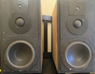
I'm relatively new to speaker building, only last summer, I restored a pair of 1971 Klipsch H700 Heresy speakers that I rescued from a dumpster on my job site almost 17 years ago:
IMG_0771.jpeg


IMG_1013.jpeg

Frankly, I was underwhelmed by the results: the highs were sibilant and harsh and the tone was boxy and dull. I was easily persuaded to do @claudej12000 's Super Heresy mods, which I found more to my liking, but there remained some shortcomings from the stock, Decorator cabinets, namely the thin plywood transmitted too many resonances and while I considered bracing them, I felt that they needed their own boxes with proper baltic birch to really shine to their full potential and I made a pair from scratch, put the H700's back to stock and sold them off.
IMG_1939.jpeg


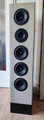
The super-H clones satisfied me for a while, but what they really did was opened my eyes to the beauty of horn speakers. Eventually, I kept wondering if they could be better and since I wasn't satisfied with the finish job I did on them, I decided to give them some mods to improve their sound, with an eye on building pair of "lifetime" speakers, somewhere down the road. cutting to the chase, I arrived at a set of mods that made them the functional equivalent of a pair of Klipsch Forte's, adding a bass extension bin with a 15" passive radiator and going through a series of mid horns, before settling on a K510 clone and a 2" driver, a PRV Audio D2200PH and one of Dave Ault's fantastic L-MAHL tweeters. Visually, it was a bit of a kluge, standing at over 4' tall and looking more like a collection of parts than an integrated speaker, but sonically, if was a few steps closer to audio nirvana and pointed the way to what I thought was my endgame speaker, envisioning what PWK's vaunted and short-lived Cornwall replacement, the Chorus, might sound like with a bigger mid horn & driver and a super tweeter.
IMG_3978.jpeg


IMG_5278.jpeg


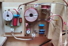
It's not pretty, but with a little help in designing the crossover network, a modified ALK Universal and ultimately Bi-amping them with a Dayton Audio DSP 408, an Emotiva MiniX A-100 pushing the woofers and a lightly modded 15-Watt, P/P Glow Audio Amp Two driving the horns, the low-end played down to 30Hz, while the mids dipped down to just under 500Hz, filling my living room with luscious clarity and dulcet tones, bringing me one step closer to audio nirvana. However, as I began collecting parts and pricing out materials for the Super Chorus project, I ran into some roadblocks: my goal was to make them with the same internal volume as a Cornwall but leave behind the vintage box look for something a little more contemporary, with thick, solid wood motorboards, with diffraction bevels for a more up-to-date look. The only problem was that since the pandemic, the cost of materials has gone up exponentially and the price of 1.5" Walnut or mahogany began to make the intended build cost prohibitive. A chance encounter at a listening room in my neighborhood provided another option: LaScala clones:

IMG_5457.jpeg


To be honest, La Scalas had always seemed a bridge too far for me: their footprint, at 24" x 24" x 36-ish took up a lot of space and I couldn't justify them in my own mind, let alone consider WAF. To that end, my proposed Super-Chorus, at roughly 19" x 16" x 48", took up far less floor space and were only slightly larger than my Frankenstein Heresy/Forte/Jubilee experiment. However, hearing these ratty old LaScalas, even in a less than ideal configuration and setting, changed everything. Even my spouse was onboard after hearing them that night. With my eyes on an even better endgame , goaded and enabled, I scoured the internets for plans and instructions to make my own, top-ported La Scala clones. Plans in hand, I ordered material- 1" baltic birch or its alternatives aren't available anywhere in my area, so I settled on 1" maple-faced, poplar core ply for the bass bin cabinets and motorboards, while the doghouse would be constructed from 3/4" MDF, the upper horn enclosure will be made from a 3/4" Baltic Birch alternative, Spartan-Ply, while the entire cabinet will be painted piano black and face-trimmed with 5/4" Mahogany.

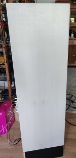
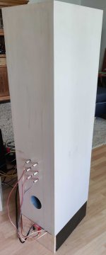
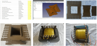
Even with my 30 years of experience as a master carpenter and cabinet maker, I was a little daunted at the perceived complexity of the bass bins, however, I was able to knock out the parts in less than an afternoon:

IMG_5666.jpeg


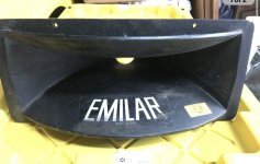
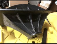
Instead of the K510 I'd used before, I opted for the popular 10' x 18" horn. I had a bad experience with ZXPC, where they sent me the wrong horns that were also damaged and refused to return them, so I opted for the the PRV version, which is substantially thicker. I've got it mocked up on a baffle board below with a K-792-K, but ultimately, I'll use an L-MAHL Machined Audio Horn Lens with a B & C DE10 driver.

IMG_5630.jpeg


IMG_4566.jpeg

I sliced my speaker cone!

I was curious about the effect of slicing and coating a speaker cone in a similar way ScanSpeak do.

So here you go. Original driver, measured 80dB @ 30cm (at least according to my phone SPL meter).

dayton-audio-rs180p-4-7-reference-paper-woofer-4-o.jpg

Original B4 Slice.png


Now we slice and varnish! Varnish used was two part Sayerlack TLL3097.

20211224_165325.jpg

20211224_165539.jpg

20211224_172159.jpg

20211224_165932.jpg


After Slice.png


I'm amazed the results are so damn similar before and after such brutal slaughter of the driver!

Attachments

  • 20211224_165325.jpg
    20211224_165325.jpg
    377.8 KB · Views: 246
  • 20211224_172159.jpg
    20211224_172159.jpg
    483.1 KB · Views: 223
  • Like
Reactions: HiFiCompass

Balance Potentiometer with only 135° usable Angle of Rotation - what Benefit?

By checking an integrated amplifier (Harman HK-610) I note crackling by rotation of the balance knob (usual on old amplifier stuff).

Upon closer inspection it turned out that this contact problems on this stereo potentiometer occurs only close to the center position.
It's about this part of Alps according SM: VR-501/502: Part-No 5113-S2005104, 100KΩ

After desolder and dismantling this part (because I assumed an internal deficiency due oxidation etc.),
I measure zero ohms from center tap to left and 100KΩ from center tap to right on slider track of first channel and the same, but vise versa on the second channel.
Thus only 135° usable angle of rotation is available.

On the first both attached jpg files the difference between one half of slider track surface and the other can also be seen visually.
I've never seen before this kind of slider track in balance pots - but it seems to have been widespread.

What is the correct naming of such potentiometers (without keyword I can't find information by google) ?
What benefits are to expect by using such versions for balance control in opposite to usual versions ?
Are ALPS datasheets of such kind of potentiometers available ?

Thank you very much for comments.

Attachments

  • DSCF8760.JPG
    DSCF8760.JPG
    279.2 KB · Views: 198
  • DSCF8761.JPG
    DSCF8761.JPG
    289.5 KB · Views: 205
  • DSCF8765.JPG
    DSCF8765.JPG
    298.6 KB · Views: 151
  • DSCF8767.JPG
    DSCF8767.JPG
    183.5 KB · Views: 176
  • DSCF8768.JPG
    DSCF8768.JPG
    150.5 KB · Views: 171
  • DSCF8769.JPG
    DSCF8769.JPG
    185.7 KB · Views: 165
  • DSCF8771.JPG
    DSCF8771.JPG
    437.7 KB · Views: 184

Active Baxandall tone amp design ideas

Hello all and Happy New Year!
For any with experience designing Baxandall tone control amps, any tips or observations on this design before I send it off for fab?
Works well in LTSpice and breadboard, but can't hurt to have some feedback while it's still on the drafting board.
Application is a replacement PCB for the tone control amp in my Pioneer SX-750 receiver.
Cheers,
Mike
2023-01-07 (1).png
ToneAmp2.jpg

The Impact of Taller Waveguides on HORIZONTAL Beamwidth

As usual, I'm trying to come up with a speaker design that will have narrow vertical directivity and wide horizontal directivity.

I built some CBT-ish things, and I made a Unity horn that worked pretty well.

The issue I had with the CBT was that the top end wasn't great (a known issue with all types of line arrays, even curved and shaded ones) and the Unity horn I made had a very low WAF score

This got me looking into Horbach Keele arrays, which are basically a refined version of a WMTMW

While working on that, I realized that I had very very little width to play with (due to WAF) but a lot of HEIGHT to play with (also due to WAF)

So I wanted to learn: Does making a waveguide taller change it's horizontal beamwidth?

IE, we definitely change the VERTICAL beamwidth of a waveguide when we make it taller, but is there a change to the horizontal beamwidth?

Let's find out...

Aiyima-1000w,irs2092

https://onl.tw/1pE3mQq

Hello. I purchased this amp board and tried to test it, but there's no normal sound output. The power indicator lights up, and the fan is running, but I only hear crackling and noise that doesn't sync with the music's rhythm. I'm using two 36V switching power supplies as the dual power source. If anyone has experience with this amp, please provide some advice.
16976666232128301171953552214426.jpg

Dynaudio Drivers

I am looking for a home for this pair of Dynaudio home built cabinets. Includes (2) D-21AF high frequency tweeters, (2) D-76 AF soft dome mids, and (2) 21W54s. See picture.
I am located in northern California and would prefer not to have to ship them but will if need to. These have been sitting for about ten years and are a bit dusty. The 21W54s were reconed once and probably need to be done again. $100 or first offer.

Attachments

  • IMG_7009.jpg
    IMG_7009.jpg
    448.8 KB · Views: 193

Balance Pot Wiring

I would like to add a balance control to a design that I'm working on, and have been able to find surprisingly little information on the proper way to incorporate one alongside a volume control. I have installed one, and it works, but I just want to make sure that there isn't something that I am not taking into account here. I have placed a 22k resistor in series with a 10k volume pot to limit gain. This amp uses 6GC5 beam pentodes for the output, and is driving headphones, so it is capable of delivering FAR more power than is generally necessary. That 22k resistor lets me max the volume out (and get hearing damage) without any clipping whatsoever. I placed an MN25K pot right after the volume pot to act as a balance control. My concern is that the resistances of the two pots in series is doing something that I am not considering. It sounds fine, but I want it to be done properly. I also tried a different technique that I found. That is, I used a linear pot with its two outer legs attached to each channel and the wiper grounded. With that, only the last ~20% or so of the pot actually changed the volume of either channel. IE, the middle 60% of the control did nothing at all. I tried everything from a 10k to 100k. Same effect, though the middle "dead zone" shrank with the smaller pot. Not completely though. Anyway, I'm feeding a 6DJ8 here.

Attachments

  • balance pot.jpg
    balance pot.jpg
    203.7 KB · Views: 808

Kenwood Basic C2 tone control issue

I recently refurbished a Kenwood Basic C2 preamp and it sounds great but there is an issue: When I select either turnover selection for BASS or either turnover selection for TREBLE the volume drops out altogether. Also, after increasing volume to be able to hear, there is no discernible effect when operating either the bass or treble controls in any of the three switch positions. Something is definitely not working correctly. With all four switches set to ZERO it sounds fine but I have no control over bass and treble response. What do you think was missed in the rebuild?

Marantz 250M clipping artifacts

Just finished rebuilding it. One board was burnt. After rebuilding both boards, I'm testing it and it works fine, except when clipping, as can be seen in the pictures. At low frequencies seems to clip clean or I cant see it, but on higher frequencies does this(8ohm load):

IMG20220325112455.jpg

IMG20220325112825.jpg


I have replaced almost every transistor in both boards, because the blown board had most of them bad. Both boards behave the same. And important to mention, they were modified like the ones on this thread:
https://audiokarma.org/forums/index.php?threads/some-info-on-my-250m-please.744954/
As it seems that modification appears to be factory made, because looks exactly made as the ones on the thread, I didn't undo it. Apparently, it replaces the current limiting adjustment pots, someone draw the mod, but I think it is not totally correct, there are at least two diodes that doesn't appear:
IMG_0494.JPG


As said, if you don't drive it to clipping, everything seems ok, but I don't like that waveform at clipping, and don't know if it is a recovery problem, or it is caused by the modification to the current limiting circuit, and what can I do to eliminate it.

FS (Austria/EU) REL S-5 SHO, Allen Wright Sony SCD-777ES, Kuzma Stabi 2 incl. Stabi PSU, Ortofon 2m Bronze, Ortofon nude AlNico SPU, tubes and more

I mostly enjoy reading posts here on this forum rather than chiming in myself since I somehow managed to find an audio system with which I simply can enjoy the music and not get any "upgradeitis" anymore and the days of DIYing tube amps are over for me. If you were hoping that I would sell my DHT tube gear here, I must dissapoint you, at least for the time being since this post shall serve the purpose to sell some gear that is only seldomly or not at all in use any more.
That is for now:
-A black REL S-5 SHO subwoofer (used, visual scratches but fully functional) that served me well but has some scratch marks since I once purchased it used with the goal to refinish it but never got around to it because the subwoofer was not moved from its spot once I found the perfect place in the room and after pulling it out of my system, the project had very little priority.

-My wonderful and rare silver Allen Wright Sony SCD-777ES (used, fully functional, in top condition both visually as well as functionally) modified by no one other than Allen Wright himself with his Level 6 modification, or at least I was told that would have been the closest equivalent commercial modification since the SACD-Player was once in his personal system. I hope I don't regret this decision to sell the Sony since it is near and dear to my heart and that only partly due to its history and primarily due to its sound, especially when playing SACD's but also with normal redbook CD's, whih is an experience time and time again that renderes me speechless. Attention: 1) For the balanced outputs, the Sony features Allen's preffered Redel connectors instead of XLR's, but that's an easy mod for anyone who wants to change them out or is able to DIY cables. 2) The Sony is a bit of a diva and wants to be treated right, meaning it needs its warmup time, a solid 30min at a minimum before sounding its best and switching between SACD and CD playback can sometimes be finnicky, in the sense that the Sony doesn't occasionally not immediately detect a SACD correctly. Maybe I will delete the Sony from the list if I change my mind that I only need my vinyl setup and that for the rest of my listening streaming is far more convenient and the Sony just not worth the hassle but for now this gem is up for sale, so be quick. If someone is also interested in my SACD collection, I would be willing to sell it or a great deal of it as a bundle together with the Sony or seperately but in that case no single SACD's.

-An Allo USBridge Signature incl. Shanti PSU (used, all in perfect condition) that both served me well in my second system but as my focus now lies on vinyl and I am reducing my gear to what I need for my primary system, it too needs to go.

-My great black Kuzma Stabi 2 incl. serviced Stabi PSU (used, turntable with little scratches on the outside that it had since its first spin and otherwise in top condition, PSU in perfect condition) that served my second system well and can be sold together with a currently mounted and perfectly adjusted Ortofon 2m Bronze with little wear.

-An amazing nude Ortofon SPU with AlNico magnets (little use since its service by Ana Mighty sound) featuring a Line Contact III stylus, boron cantilever, new silicone damper, 20mN tracking force, 90 micron/20mN/315Hz lateral tracking and 1.9ohm/ch DC coil impedance.

-My Sennheiser HD-650 headphones that were trustworthy companions throughout my audio journey but I decided to part ways with and only keep my 600's and old AKG's for the rare cases in which I need a pair.

-Tubes and more tubes all measured NOS, some matched...message me if you want the list but the main types I am willing to sell are just the tubes that I happen to have that are not DHT's and not power tubes.

I will include prices in my next post with the photographs. They are, however, negotiable as my primary concern is that my gear is in good hands and will be used again and not collecting dust.

Buyers for the bigger items like the REL subwoofer, just as heavy Sony SACD-Player and the Kuzma turntable are ideally located in Austria, but I am open to discussing shipment in the whole of the EU at the expense of the buyer.

Photographs, manuals if existent , and links to the manufacturer's websites or old articles will follow as soon as possible, hopefully this weekend, but feel free to send me a PM even before that if you are interested and I will quickly try to get back to you.

I hope that I managed to get the attention of some fellow music lovers, audiophiles and DIYers. Don't hesitate to send me a PM if something caught your eye!

Best, or Liebe Grüße as we would say here where I live,
M.

Panasonic EZP-E capacitor - 10% tolerance

I have a lot of this in my possession. Brand new from Farnell 25uF 1300VDC version. I use it for my crossover and it sounds warm with no harsh and revealing. Very good for my bass and mid driver.

Describe by Tony Gee from Humble Homemade Hifi "one of the most neutral sounding capacitors available in the low to medium budget range".

USD 3 each - Selling it lower that listed on Farnell. I take paypal. Please send me your location for exact shipping cost. Bare in mind this cap is huge. I'll find the lowest cost for shipping

Humble Homemade Hifi - Cap Test

https://my.element14.com/panasonic/ezpe1d256mta/cap-25uf-1-3kv-film-radial/dp/3296041?ost=3296041

https://www.newark.com/w/search?capacitance=25uf&st=panasonic%20ezp-e&showResults=true

Caddock MP930 vs aluminium housed resistor

Hi All
Direct coupled tube amplifier 11HM7 and GM70,11HM7 (12GN7a) triode connected,anode direct connected to GM70 grid. I can connect the load aluminium housed resistor 12K or caddock mp930 5K+5K+2K on three separate heat sink to anode 11HM7 and grid GM70.

View attachment ATE Resistors2.pdf

View attachment MP9000_Series.pdf

I tested both loads with square wave separately on the table from the generator through a 12k carbon resistor and in the amplifier. The oscilloscope memorizes the impulse of the first load in memory, then I switch the load with the toggle switch and observe the impulse of the second load. With the recall button I select the impulse of the first load and watch both impulses at the same time. The pulses on the anode 11HM7 -grid GM70 are the same at all frequencies 10Khz,100Khz,1Mhz.Full pulse coincidence on the oscilloscope screen.Parameters are the same. Please advise which is better resistor for sound.

100Khz_0.jpg [/ATTACH]Amp_1.jpgAmp_2.jpgCaddok-Wirewound_2.jpg

Attachments

  • 1Mhz.jpg
    1Mhz.jpg
    494.2 KB · Views: 285

Orion 225 hcca need help with identifying resistors

I have 2nd gen 225 Hcca that I’ve owned since the mid 90’s. It’s sat for a couple decades in a tub waiting for me to repair the channel that quit working at some point. I’ve included a photo of the resistors that I can’t Identify. Pictures I’ve seen online are difficult for me to determine the band colors. Can someone tell me the values or colors?

Attachments

  • IMG_1791.jpeg
    IMG_1791.jpeg
    465.8 KB · Views: 91

Question of 17KV6 plate dissipation

Hi all,
I recently bought some TV tubes in the second-hand market, such as 6LU8, 17KV6A, 6HB5, 6JN6, and so on. Then I planned to use them to make a single ended audio amplifier. I looked up the data sheets of these tubes and found that the maximum plate dissipation of 17KV6A was 28W or even more, which confused me. I saw that the plate area of 6HB6, 6JN6 tubes was almost the same as that of 17KV6A, but they only had a plate dissipation of no more than 18W. I don't know why 17KV6A can consume such high power. Can anyone explain?

Thank you!
20231028085222.png
20231028085436.png

transistors biasing for YBA intégré Delta DT

Hello, everyone , i'm repairing a YBA built-in Delta DT I already changed all the power transistors (TIP35 & TIP36) and also change the 2 transistors for bias adjustment (reference BC547?) Plus Two adjustable resistors for the bias, the amplifier turns on properly, but I can not adjust the bias, with a multimeter, the values do not move! I do not know if the 2 transistors bc547 are the right reference for this amp? Because the manufacturer has erased all the references of its parts on its components, does anybody could provide me the references of the parts of the transistors for the bias and also to what value it must be adjusted? 1.6millivolts ?? thank you.

Attachments

  • 7d90cd362abba0253f0b4bfd772ab454f0889090.jpg
    7d90cd362abba0253f0b4bfd772ab454f0889090.jpg
    129.2 KB · Views: 1,010

OB Speaker Suggestions

Hello all, been a lifer in the audio industry,fueled by my first love, music, and recently bitten by the DIY bug. I have googled ad nauseam trying to gain some insights, unfortunately when it comes to understanding the complex interactions of all the parts my head is about to 🤯 What I am looking for is a floorstanding, narrow, high efficiency and passive xover. Some that seemed appealing are the Decware ZOB and the GR X-Static, this 1 is particularly interesting as there is a flatpak cabinet available. If I had my wood working tools set up where I currently live I would be inclined to build the cabinet, that being said I could probably build a cabinet if it isn't too complex.

Braided copper wire (lead wire) won't solder by any means, and has textile threads on it?

I'm having an issue that seemingly no one, not even the guy who sold me the wire has.

I bought a thin braided copper wire for repairing a loudspeaker (as I did dozens of times before), and I can't solder it no matter how much flux I use on it.

I had difficulties soldering braided wire before, but never this much.

I warned the guy at the store and he said he himself was using that same wire the day before without a problem, but I didn't manage to solder it by any means, it just darkens and smells to burnt fabric.

And, by the way, this braided wire is made with copper and (apparently) cotton.

Each "thread" of the braid isn't a round copper wire, instead it's a small flat copper strip twisted around a cotton thread. So, while twisted, it looks like a thin copper string with cotton coming out of its middle. It catches on fire if you expose it to a flame, but that doesn't help soldering it at all.

But I couldn't find any information about such type of braided wire on the internet, none mention fabric threads in the wire.

And the only solution I found for soldering it was to fold the tip of the braided wire in the end and then wind a naked copper wire tightly around that end, and solder that wound copper wire, mechanically locking the braided wire inside it.

Is that anywhere normal?

Things are worse because it seems like an exception and but I had to use that braided wire to make a instruction video, and perhaps no one will understand why I had to do what I did.

Question about my board from AliExpress

Hello everyone, I bought this board from AliExpress a couple days ago and the configuration printed on the silkscreen except the power capacitors which were 4700uF instead of 2200, gave me pretty good results but I think I can improve further. I would also like to know how the PCB is configured for power, is it single or split? What about a TDA20XX? I only have a 14-0-14 100VA transformer and would like to get the best sound clarity with a flat response. Thanks a lot!

Basic crossover advice for DIY musician

I'm a musician putting together a combo amp for guitar & vocal. I've chosen a class D amp which is designed to output to a speaker cabinet anywhere
between 4 and 8 Ohms. So, to get the most power out, I want to run it to a speaker arrangement for 4 Ohms. The speaker I've chosen (Celestion BN12-300S) is available in both 4 and 8 Ohms.

I already have some 4-inch 60 watt 8 Ohm Faital drivers. Ideally, I'm hoping to use one or two of these Faitals to handle
the higher frequencies in a crossover arrangement with either the 4 or 8 Ohm Celestion, so that amp is seeing 4 Ohms.
Any advice would be much appreciated.

Philips DAC960

Hey all,

I modified my DAC960 per the "pooge" series of articles in Audio Amateur some 20 years ago.
At the time I worked for Tektronix as a technician and had a well equipped stockroom to obtain parts from. The good old days.

I have used this DAC ever since. I have on occasion compared it to some fancy CD players, but always liked this better.

Anyway, wandered away from DIY for quite a number of years, come back here and see the TDA1541A is still enjoyed by many.
I knew nothing about Crowns, Double crowns and the like.

So I looked inside mine.......No S1, no Crown. Date code indicates it was made in 1987. HSH8749 2 Y

I guess I'll look for an upgrade.

Three of us audio heads bought the DAC960 to mod. One of the guys never did his and gave it to me for free some years later. So I actually have a stock one. I never have listened to it.

No questions really, just an interesting story.

Ron

Updated Open Baffle project: Active with Hypex Fusion FA123

Hi all

After some time of inactivity I am now working on my open baffle project again. See here: https://www.diyaudio.com/community/...ng-bass-driver-and-u-frame-side-wings.384160/

In the meantime I have made some decisions for the drivers and also ordered them to setup a prototype:
Tweeter: AMT23D6.1-R (88dB, 8Omhs)
Mid woofer: Audiotechnology C-Quenze 18 H 52 06 13 SDKA
Bass woofer: Acoustic Elegance Dipole12

With just minimal passive crossover it already sounded promising. I then made the decision to get rid of my AMP and convert the into active speakers with Hypex Fusion FA123 plate amps. These are also here already and I am trying to set these up. I just got them working with some preliminary sane filter settings.

My question now is: The filter design software hase some built-in features to measure the response directly in the design software. I did not manage to get that running.
I am using a UCA202 audio interface, installed ASIO drivers which I can select in the software but I do not get the "button" where I can enable the recording feature. What is strange is that the ASIO settings for device and input output channels are not saved. When I go back to thsi dialog the settings are gone...

Has anyone succesfully used this recording features in Hypex Filter Designer?

help wiring amp for both balanced and single-ended mode

the amp is currently wired for balanced input and output.

If I want to use a single-ended input (example: using a normal RCA cable), what changes do I need to make? How do I re-wire the amp (if required).

Thank you.

EDIT: I assumed (maybe incorrectly) that balanced mode = bridge mode since there's a dedicated channel for +/- channels.

MTM with mid domes

While discussing some possible project that i should design for someone, he asked if i could do an WWMTM with middomes in stead of cone middrivers. I tried to see if there are examples of that, but could not find any.

Is there a reason why this is never done before. Or did a mis some designs on that?

Are there disadvantages on that? Because it looks like this should make it easier to put the mids close enought to each other to work right, even with a relative high crossover point to the tweeter.

We are still in the brainstorm phase, so no decisions on drivers or so yet. It's just an wild id that need a bit tought and check on realism...

TDA2005 system making scratchy noises

Hello!

I'm trying to relive an old Becker car stereo from the 80s, and although I have partial success, I'm having some problems as the title says. I'll try to describe what I did until now just in case it could be useful.

When I first tried it, it wouldn't tune to any station, and both output channels gave thumping noises. While I was testing it, after some minutes it partially died (only the backlight worked). I checked the two voltage regulators and one decided to take a break. I had a spare so replaced it and it relived. Saw some whiteish corrosion under some caps in the power/regulators area so replaced them.

Having the voltage stabilization sorted, next was the FM section. Suspicious caps of the same brand and type were replaced, and now tunes and locks beautifully to stations.

Because the output was still noisy, went to the amplifier/tone control area and acted the same with the caps. And now, the left channel sounds superb, but on the right one I still have a scratchy noise.

I still didn't have time to review it, but the noise seems to be present on any source (FM/AM, have to try tape).
The noise is the same as a scratchy potentiometer would do, and is pretty loud even with volume at min. But it can't be a pot, since it does it without touching the radio (maybe stop for a few seconds and then it does it again) and because the volume and bass/treble, although you adjust them with pots, the actual tone control is done with a IC (TDA1524A).

I have the factory service manual and tomorrow I'll try to upload the schematic, but meanwhile I'd like to know your thoughts about this. I think I should review the amplifier stage. Any ideas what could generate this noise? Would a defective amplifier chip do some thing like this?

Thank you very much! (and sorry for the long text, but maybe it can help).
Projects by fanatics, for fanatics
Get answers and advice for everyone wanting to learn the art of audio.
Join the Community
507,540
Members
7,876,091
Messages

Filter

Forum Statistics

Threads
405,679
Messages
7,876,091
Members
507,540
Latest member
Tgeb