Hi all.
I'd like to build a simple "loudness" stage for include beetwen TV low level output and the line input in my amplifier.
I'm thinking in a operational step like LM387 or so. But I have not idea about RC filters.
I need to have a single +V for the circuit (if is +5V, better).
Thanks for your help
WebWilly
Haven't anything I can think of to recommend tbh. A proper loudness control uses a tapped volume control.
This was an odd design with limitations but might achieve what you are after at a fixed level,
http://www.diyaudio.com/forums/analog-line-level/196088-volume-control-pasive.html
This was an odd design with limitations but might achieve what you are after at a fixed level,
http://www.diyaudio.com/forums/analog-line-level/196088-volume-control-pasive.html

Real time Loudness Meter
check out this URL:
Grimm Audio
The Luxman Receiver R5030 uses a variable loudness filter - go to page 15 about sm from
Luxman R-5030 | Owners Manual, Service Manual, Schematics, Free Download | HiFi Engine
check out this URL:
Grimm Audio
The Luxman Receiver R5030 uses a variable loudness filter - go to page 15 about sm from
Luxman R-5030 | Owners Manual, Service Manual, Schematics, Free Download | HiFi Engine
Attachments
This is a passive loudness circuit that can be put on the end of a pre amp...
The effect as you turn the pot over full rotation is...
The 33k resistor is just to simulate a typical load and is not needed it will drive a following circuit over about a 20-100k range withought very much change in the frequency response.
The component values can be scaled to for instance use the 10k motorised pot widely available here in Oz. In this case just double all resistors and halve capacitors.
rcw
Ecaxt basically Design Rules for variable Loudness Control wanted
How I calculate the necessary elements for the network, if I know already the value for my speaker efficiency?
About the URL
http://www.diyaudio.com/forums/solid-state/154209-reverse-old-loudness-control.html
I read a lot of informations but not the right way therefore.
About
http://www.google.de/search?q="loud...WE4gT0poH4BQ&ved=0CEEQ_AUoAQ&biw=1280&bih=857
there are a wide range of examples, but no clear guidelines.
Thank you for advices.
in this case this could be of interest:
http://www.sfxmachine.com/docs/loudnesswar/loudness_war.pdf
check also out at the end of this article the mentioned references.
Last edited:
You have no need to calculate anything, that circuit just goes between a pre amp and a power amp.
These days there are many circuits around that have multi-band dynamic compensation and so on, but that is a simple passive circuit similar to the ones found in such things as Mac Intosh amplifiers of the sixties and seventies.
If you want something fancier than this in the analogue domain, things get very complex very quickly, that's why the digital chips have appeared, if you want an all singing all dancing one, use one of these.
rcw
I can't find the McIntosh schematic, but the one I described has a 10k linear pot, an installation of it is here...
Hi-Fi Projects Extraordinary POQX Analogue Signal Processor
rcw
Hi-Fi Projects Extraordinary POQX Analogue Signal Processor
rcw
That's interesting, thanks. I would have thought log taper would be more appropriate. Once you set the volume pot, you're using the loudness pot to vary the SPL in the room. So it seems a log taper would be more "ergonomic". I've had Yamaha amps with this feature and it worked well, but never looked to see what kind of pot they used. I assumed log.
Very interesting. And, what about using it in an Integrated Amp which has the pre-out and main-in already linked inside?This is a passive loudness circuit that can be put on the end of a pre amp...
The effect as you turn the pot over full rotation is...
The 33k resistor is just to simulate a typical load and is not needed it will drive a following circuit over about a 20-100k range withought very much change in the frequency response.
The component values can be scaled to for instance use the 10k motorised pot widely available here in Oz. In this case just double all resistors and halve capacitors.
rcw
Hi,
excuse me my ignorance and reviving an old thread...
In above schematic one end is connected to the common, can anybody tell me where the other three ends are connected to?
Also what kind of caps should I put there.
I am putting together an TPA3116 D-class amp with 6N3 tube preamp, so I am looking for a tone tuning (bass/middle/treble) and loudness circuit that I can bypass (on/off) based on my needs...
So if there is a simple, passive solution without significant signal degradation, please let me know.
I know some basics and have some skills soldering and mostly breaking stuff, but here I am just a beginner, so every detail counts...
Thanks in advance
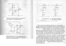
Top left is the input, the output is from the wiper of the pot and the lower trace is common ground connection.
Caps would typically be polyester film capacitors.
Mooly, thanks for the info.
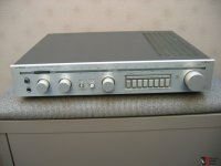
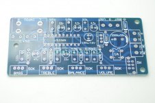
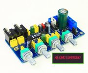
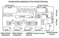
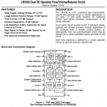
Later on today I bought a finished tone board with loudness based on LM1036N chip from TI.
I need to check tone caps quality on that board and maybe find if I can make variable loudness control on it...
Here are some photos and diagram, so if anyone can recognize what is there to tweak...
Attachments
- Home
- Source & Line
- Analog Line Level
- Loudness stage