After repairing my bd1000 with Perry’s help and finding it fun I decided to get a few broke amps on eBay and give them a go. 600.4 board 3085-a
Broke rcas replaced. Played audio at this point but only tested for a few seconds. One buz fet was physically chipped. Replaced all outputs with 540/9540’s. Replaced all source resistors as a few looked burnt. Set bias using 50ma increase method per channel. Idles at 1.2a (1.0a with all pots fully ccw)
Amp plays across all channels individually at low volumes. When testing it drew about 2-3a. It will randomly cut out for 1-2 min and come back on its own. Power light stays on. Rail-rail voltage drops to 20v. Input power drops to 0.5a. Once I cycled the remote off/on and it came back to its failed state. While probing my hand slipped and ended up burning 2 psu fets on same side.
With the blown irf1010e cut out I limped the amp along to see if I could get it to cut out again. It happened once or twice then eventually not at all. By now the amp is warm. Maybe the warmer it is the less likely it will cut out? Or the fets that burnt were part of the cut out issue too.
I’m going to replace all 3 psu fets on the burnt side and probably the other side as well. Maybe when it cools overnight it will cutout for longer to give me a chance to poke around more.
Is there a likely cause? What can cause rail voltages to drop, and stay symmetric, without excess current draw ?
Were you supplying it enough current when it was cutting out?
Replace all of the PS FETs. I'd use IRF3205s.
Also confirm that all gate resistors are within tolerance and that the drive signal is good. Do this with the FETs in the circuit but with no B+ supply voltage.
Replace all of the PS FETs. I'd use IRF3205s.
Also confirm that all gate resistors are within tolerance and that the drive signal is good. Do this with the FETs in the circuit but with no B+ supply voltage.
Yes it had plenty of current available from a modified server psu.
Roger that on psu fets. Psu gate resistors measure within 1% of 10 ohms. Can I get away with keeping these with 3205’s?
Is there a failure mode of this design that is intended to have the psu put out a fraction of its full output? Or possibly a sign of the tl494c going south?
Roger that on psu fets. Psu gate resistors measure within 1% of 10 ohms. Can I get away with keeping these with 3205’s?
Is there a failure mode of this design that is intended to have the psu put out a fraction of its full output? Or possibly a sign of the tl494c going south?
You have high and low voltage protection, thermal protection and those are in the power supply via the LM339. You need to look at the voltage on the various output pins of that IC when the amp is working and when shut down to see which is causing the shutdown.
The 494 could be defective but I doubt it unless the 5v regulator is out of tolerance.
Yes. You can leave the 10 ohm gate resistors.
The 494 could be defective but I doubt it unless the 5v regulator is out of tolerance.
Yes. You can leave the 10 ohm gate resistors.
Last edited:
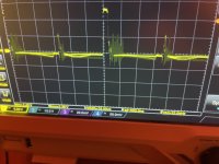
Ok, all ps fets replaced with irf3205. With just remote and ground, no battery positive, the gate signal is a really clean 32khz square wave approximately 43% on. With b+ it is the mess that is pictured. I’m not expecting it to look exactly the same but that looks noisy to me.
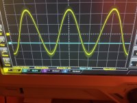
The amp works but the switching noise is bleeding to the outputs. Pic attached. If you decrease the period to zoom in you can see the 32khz psu switching riding the output.
I don’t think it’s the scope setup. The other 500x I was measuring had clean output. I went as far as powering the scope off a battery/inverter. It’s there load or no load on the output. If this is normal can any mods be done to improve it?
Attachments
Didn't the 500x have noisy rear channels?
Was the scope grounded to the non-bridging speaker terminal when you checked the output signal?
Was the scope grounded to the non-bridging speaker terminal when you checked the output signal?
The other amp rear channel noise was fixed by connecting the front/rear rca shields. Looks like it uses “I” and “j” grounds with the 100ohm resistance. This amp has the rca shields tied together internally without any resistance.
I tried it with the scope test signal ground lug tied to the psu running the amp. I removed this ground and then tried the probe ground on the channel being measured - just measuring single unbriged channel. I also improved the noise in my setup a lot by using a car deck on the same psu as the amp per one of your past tips (vs the portable AA battery cd player before).
I also tried a second probe feeding the math function to do a differential measurement. One probe on channel + one probe on channel ground. Also tried it on the bridged ground. All same result.
That noise is well out of the audio band. Do you think it's a problem? Some amps are a bit noisy.
Is the bias set for every channel?
Is the bias set for every channel?
I’m unsure if it’s a problem honestly - my understanding of the theory involved is weak. I just wanted to verify it wasn’t a sign of a fault.. If your opinion is that level is ok then great.
Bias are set but… are you supposed to do it after the amps warmed up or is cold ok? Also… after it’s set, how much variance is allowed for the voltage across the source resistors within the same channel?
Also - how much variance is acceptable between the output of left and right channel of the same pair? For example with a 50hz sine wave driven to before clipping is 18v output on left vs 19 or 20v on right ok?
The bias is set after the temperature stabilizes, typically just a minute or two for this amp (and most amps).
I don't generally look at the individual resistors in a channel but ±5% would be OK. I generally use matched outputs (from the same batch) and 1% emitter/source resistors to help ensure current sharing. I use voltage across resistors at higher power to determine current sharing.
I would expect both channels to clip at the same level but board layout or differences in components could make a small difference. What would be more important is that both channels clip symmetrically, top and bottom.
You have to realize that this is analog/linear audio. This isn't some digital device where you can have results that are going to be absolutely the same.
I may have had the bias too high. I turned the pots all ccw again left the amp on for a few min (after being off overnight) zero load, and reset each channel for 50ma idle current increase. Source resistor voltage barely measures anything. They were all 0.0-0.1-0.2mv…. Pretty much measurement error of 1 count on any dmm. Maybe I should go a bit higher?
The output looks much cleaner now.
I got it to start cutting out again to point where power light went off but it was really hot. Will have to get temp gun out again but if I’m following schematic right pin 2 on lm339 controls the over temp protection and it was at 0v
The output looks much cleaner now.
I got it to start cutting out again to point where power light went off but it was really hot. Will have to get temp gun out again but if I’m following schematic right pin 2 on lm339 controls the over temp protection and it was at 0v
Did it overheat at idle or after a long period of time when driving audio into a load at high volume?
Definitely not at idle. It was maybe 1/2-1hr of playing 50hz sine test tone off and on checking for the noise at 30-50a input current into 4ohm bridged x2 dummy load
Idle current was just a hair above 2.0a. Will probably be 2.1x after readjusting another time. I’ll leave it idle but I don’t believe it’s going to heat up much.
Idle current was just a hair above 2.0a. Will probably be 2.1x after readjusting another time. I’ll leave it idle but I don’t believe it’s going to heat up much.
For testing, I'd use music driven intermittently into clipping. This is the song I generally used:
Readjusted bias again going for 1.0mv at the source resistors instead of the 50ma rule. I didn’t measure each channel but total idle ended up being in the 2.2-2.3a range.
How much time with music testing at intermittent clipping should one expect before amp shuts down for thermal? Temp gun shows 80-85c which seems to match other posts. I got maybe 15-20 min from both amps. It’s hard to tell what intermittent clipping is as the scope just dances everywhere with the music. Seems too short but maybe that’s normal with resistive loads. 4 ohm per bridged channel
How much time with music testing at intermittent clipping should one expect before amp shuts down for thermal? Temp gun shows 80-85c which seems to match other posts. I got maybe 15-20 min from both amps. It’s hard to tell what intermittent clipping is as the scope just dances everywhere with the music. Seems too short but maybe that’s normal with resistive loads. 4 ohm per bridged channel
The time depends on the amp but the minimum rated load, resistive is tough. I generally use resistive loads but go for 2x the lowest rated load.
Did you check the idle current again while the amps were hot to confirm that it hadn't drifted much (if any)?
Did you check the idle current again while the amps were hot to confirm that it hadn't drifted much (if any)?
Maybe 100ma difference at thermal shutdown vs idle. How much is too much and what can/should be done about it?
100ma from the 12v supply is OK.
Acceptable? I don't have a definitive number that would apply universally. 100ma is acceptable. An increase of several amps, not normal... for most amps.
What can be done, practically, it would vary. Again, there would be no universal definitive answer.
Acceptable? I don't have a definitive number that would apply universally. 100ma is acceptable. An increase of several amps, not normal... for most amps.
What can be done, practically, it would vary. Again, there would be no universal definitive answer.
Man… this thing is killing me. Up until now I’ve been testing with dummy loads and occasionally a scrap 5” I’ve had laying around. Today I hooked it up to my living room mains.
There is static coming from all channels. If I turn up the bias on any ONE channel until it’s absurd like 20mv and idle jumps from 2.3a to 3.5a the noise goes away on ALL channels. It doesn’t matter which channel I turn up, all channels become quiet. I can also turn up each channel until I get 7-8mv at the source resistors… as long as the idle rises to 3.5a or more
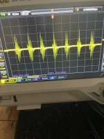
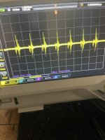
I think I just never noticed it before because no tweeter was ever involved. Scoped each channel - they all look the same. First attachment is while staticky with normal bias. Second is the high bias clean sounding. This is with no input.
Of course I’m not expecting it to be flat as this is at 500mv/div but just illustrating the difference between the situations. It’s as if the psu has a minimum load. The trans whines a normal amount and manipulating the coils doesn’t make a difference but with the high bias/idle the trans also quiets down.
Attachments
- Home
- General Interest
- Car Audio
- Fosgate 600 4 channel


