Matched quads of Toshiba 2SK1530/2SJ201

Unused/unsoldered NNNNPPPP matched quads (8 pieces) of Toshiba 2SK1530/2SJ201 for your Pass amp project(s). Purchased several sets from the F5X group buy back in 2013, but it's not fair for me to continue stockpiling transistors, so I'm selling the sets I don't have plans to use.


Two sets available. $80 plus shipping.


The measurements for the specific devices and sets I'm selling are attached so you can see what sort of matching was involved.

Attachments

  • Screen Shot 2020-02-29 at 8.29.02 PM.png
    Screen Shot 2020-02-29 at 8.29.02 PM.png
    98.1 KB · Views: 205

DIY TDA1543 DAC

Hello everyone.


I've been doing some reading and came across the TDA1543 DAC chip. From what I can tell it is the newest NOS chip made.


The chip itself has a S/N ratio of somewhere in the 90's, which by today's standards is not great. As I've been reading, it was mentioned that paralleling a bunch of these chips together will increase the sound quality.


I pondered up a simple schematic of 5 of these paralleled together with some output caps. The schematic is in the attachments section.


Here comes my questions:


1. How many TDA1543's need to be paralleled to sound good? I know "sound good" is a vague term though I've seen these paralleled with up to 60 chips. I would just like to know whats a good sweet-spot before they hit the point of diminishing return.


2. Some of the TDA1543 designs have a "re-clocker" which I am not sure if makes a noticeable sound benefit.


3. If the S/N ratio does increase proportional to the amount of chips added, how can that figure be calculated?


Any help would be greatly appreciated. Thanks everyone

Attachments

  • Screen Shot 2020-02-17 at 3.34.47 PM.png
    Screen Shot 2020-02-17 at 3.34.47 PM.png
    215.9 KB · Views: 733

Poor amplifier frequency response.

I am trying to sort out an Electrocompaniet (EC) AW-100 DMB amplifier and wanted to ask for help from the experts on this site.​

The idling current (bias) and the DC adjustments have been made to the manufacturer's recommendations. In use the amplifier lacks treble and is bass heavy. The first image shows the square wave response at 10kHz across a resistive load and the lack of high frequencies. EC will not give me the circuit diagrams to identify where filtering is taking place. However, they did say there was filtering in the input section. The second image is a circuit diagram found on the internet which appears to cover this amplifier.​

I think the only filtering is due to C1 and C14 which at 1000pf seems too large. If this is correct, would I see any significant improvement by reducing it’s value to 47-100pf?​

I would appreciate any comments or further suggestions if this is wrong.​

Attachments

  • EC01.jpg
    EC01.jpg
    865.5 KB · Views: 317
  • Input.jpg
    Input.jpg
    249.7 KB · Views: 318

10 Icepower modules in a single amp enclosure

Hi, we are putting the following ice power modules in a large amp enclosure in 3 separately powered groups... there will be 3 Powercon plugs (1 for each group which will be remotely powered on via Insteon outdoor outlets)
Group 1 will have 3 Icepower 50asx2 BTL amps, and 3 125asx2 bridged amps
Group 2 will have 2 Icepower 125asx2 bridged amps
Group 3 will have 2 Icepower 125asx2 bridged amps

Questions...
1: Do I make a central ground for all the amps to be grounded to, do I make a central ground for each group, or? I am assuming each group would have its own, it I do not know.

2: Fuses...what size should I get, and should they be fast blow or slow?

Suggestions appreciated.

Help with Mechanical "knocking"Noise in ARC Classic 60 Amp

I have had a modified Classic 60 for about 25 years. It worked fine with an occasional retube until a few years ago. One day after moving components around on my rack, there was a massive flash over with the expected horrendous sounds from both speakers. I shut everything off as quickly as possible.

I have always used a Tice Power Block for my entire system. It turned out that when I had plugged my CAT preamp into the Tice, I apparently did not fully insert the plug into the socket. I corrected this and everything worked fine but now there was a light mechanical "knocking" sound coming from near the back, left corner of the amp after being on for a few minutes. It was like what I would expect if I tapped lightly on the chassis with a plastic screwdriver handle. The noise continued to happen for varying periods every time I used the amp.

About a week later, there was another massive flash over and sure enough the preamp plug was loose again. Maybe my wife had bumped it with the vacuum cleaner. I tightened the pins on the preamp cord plug and pushed it tightly into its TICE outlet. Once again, everything worked fine but the knocking noise was still happening from time to time.

Then, about an hour after I restarted the system, there was another smaller flash over in one tube only and it's grid resister popped. I pulled all the tubes and checked them on my Weston 981. One KT-88 was dead.

I sent the amp to ARC and asked them to check the entire amp out, repair as necessary and diagnose the knocking noise. They replaced all of the power tubes with 6550 Russian =C=, two damaged resistors, and the 4 main filter caps one of which they said was completely open. Altogether, they charged me over $1600 plus made me buy a new box ($150) because they said the old one was "weakened" and they absolutely would not return my amp in it. However, they only bench tested the amp and failed to play it to try to diagnose the knocking noise.

So, does anyone have any ideas on what might be causing the knocking noise?

Weird Attenuator Problem

I've been working on a preamp design with a log stepped attenuator and I've come across a strange problem. Overall performance is good except when it's set to -0.5dB or -32 dB (when the stages are set 1000000 or 0000001).
When I started to probe the circuit I found that the distortion disappeared as soon as the probe touched the signal circuit.

Any ideas what's going on? It happens even when I have the probe BNC disconnected.

The attenuator is 500Ω with 7 stages (1/2, 1, 2, 4, 8, 16, 32dB) with an OPA1612 buffering the input. I originally thought that I might be overloading the buffer op amp but the result is the same with lower input signal voltages.

Ideas appreciated.
Thanks.

Attachments

  • IMG_0270.jpg
    IMG_0270.jpg
    864.9 KB · Views: 209
  • Without Probe.png
    Without Probe.png
    446.4 KB · Views: 196
  • With Probe.png
    With Probe.png
    452.6 KB · Views: 188
  • schematic.png
    schematic.png
    102.9 KB · Views: 196
  • layout.png
    layout.png
    90.6 KB · Views: 197

Replacements for 2SA1026 and 2SC1634

Good evening all

I’m working on a Sony TA-F60 with shorted outputs so I went down the circuit to see it anything else was bad and found these two transistors that are measuring a diode junctions half of the time on my Peak Atlas meter, so they’re obviously toast. In the pic that is attached they are Q109 and Q112 and part numbers are 2SA1026 and 2SC1634.

I’m really hoping to use something that I have on hand. I read somewhere that a KSC1815 would work well enough for the NPN. Of course I don’t have any, I have several KSC1845. I’m hoping someone might be able to list a few suitable replacements for both and hope that I have something. I could even go with something in a bigger package as long as it works electronically.

Dan

Attachments

  • 4A6AC886-273D-477B-AF39-649EB35EF526.jpeg
    4A6AC886-273D-477B-AF39-649EB35EF526.jpeg
    250.5 KB · Views: 177

Hole-free measurements of the effect of midrange port location in a horn

I wanted to measure experimentally the effect of midrange port location on the response of a Unity-like horn. However, I didn’t want to cut holes in my horns, test the result, fill the holes, cut new holes, and repeat. So, I bought a microspeaker whose diameter is similar to the holes I was envisioning, and which is also very thin. DB Unlimited Speakers and Transducers makes a “dynamic micro” speaker, which I bought from Mouser Electronics (part number 497-SM160908-1). I taped the microspeaker to the horn wall at different locations and measured the response. The photos and figures are an attempt to make clear what I did and what I found. Note that microspeaker locations are measured relative to the interface between the compression driver and my horn’s mouth. That is not expected to be an acoustically relevant location, it’s just convenient and reproducible.

The figure with the measurements has two sets of axes (see pdf attachment for a clearer view). The bottom axes show the raw response of the microspeaker when attached to a flat panel, and the response when the microspeaker is 70 mm from the throat of my horn. The upper axes show the measurements taken at various distances from the throat, but each response is first divided by the raw response from the microspeaker on the flat panel.

I wanted to see if I could reliably locate the response notch that results when sound emanating from the midrange port (here simulated by the microspeaker’s output) travels toward the compression driver mounted to the horn’s throat, reflects, and interferes destructively with the response travelling directly from the port to the microphone. The trend in the location of what I think is the notch (identified with a red circle on the upper axes, and labelled according to microspeaker location) is pretty much what would be expected: The notch moves to higher frequency as the microspeaker moves closer to the compression driver. There’s nothing earth-shattering in the results. It’s just a convenient experimental way of trying out different “port” locations without irreversible damage to the horn. I haven’t yet verified that the real midrange ports will behave similarly, but the trend looks reasonable.

Clearly HornResponse and other simulators provide a way of predicting the effect of port location, but 1) these days I don't have enough free time to both simulate and build, 2) the simulations require knowing the true location of the surface from which the sound reflects, and 3) I wanted to measure the behavior in my actual horn, not a simplified model of it. I don't claim that this approach is superior to simulations, it just suits me better at the moment, given the constraints on my speaker building time. I'd be interested to hear of anyone else's results if they try something similar (or if others have done this and I just missed it).

Few

Attachments

  • mic in horn.jpg
    mic in horn.jpg
    91.9 KB · Views: 508
  • CD adapter front close-up.jpg
    CD adapter front close-up.jpg
    157.2 KB · Views: 513
  • horn rear.jpg
    horn rear.jpg
    208.9 KB · Views: 506
  • CD adapter.jpg
    CD adapter.jpg
    192.2 KB · Views: 497
  • microSpeakerTwoGraphs.jpg
    microSpeakerTwoGraphs.jpg
    239.1 KB · Views: 500
  • microSpeakerTwoGraphs.pdf
    microSpeakerTwoGraphs.pdf
    168.6 KB · Views: 88

ARTEC 225D

Hello.
I live in France and I have just bought an Artec 225D amp. This one is still in its juice ....
I would really like you to help me make an initial diagnosis ... Could you provide me with an amplifier manual if you have one (even in PDF) .... I am interested. I did not understand all the subtleties of the buttons and I do not understand how and where to connect my cables for the speakers and what are all the inputs and outputs at the back of the unit...
I don’t really know if the tubes feeting the amp are the good one.
I feel like they’re not the right values.
I opened the tube and i cleaned it. But after i didn't remenber where to fix the tubes.
There are 11 tubes: 2 x ECC82; 3 X ECC83; 2 x EF86; 4 x 5881
I don't know where to place them. Couls you help me i, send amp pictures.
Thank you so much for your help.... All documentation will be precious to me ... I have to take care of this little baby of almost 25 kg...
Please I need help!

Sorry for my bad english

Attachments

  • IMG_20200229_144250 (600 x 450).jpg
    IMG_20200229_144250 (600 x 450).jpg
    90.4 KB · Views: 320
  • IMG_20200229_144402 (600 x 450).jpg
    IMG_20200229_144402 (600 x 450).jpg
    96.1 KB · Views: 389
  • IMG_20200229_144144 (450 x 600).jpg
    IMG_20200229_144144 (450 x 600).jpg
    105.8 KB · Views: 279
  • IMG_20200229_144218 (600 x 450).jpg
    IMG_20200229_144218 (600 x 450).jpg
    82.4 KB · Views: 266

earthquake 200dhc-mark2

I have a 200dhc amp in for repair. I replaced the following blown items.
1. powersupply FETS (12 total)
2. audio out puts (12 total)
3. powersupply caps
4. hip4080
5. tc4424
6. tlc271 (this was potted and burnt in the middle)

amp powers up fine on current.limiter. I have rail voltage on 3 outputs on each side (65v) and around (16v) on the 3 FETS beside the FETS with the rail voltage on each side.
some of the ic's are sanded to prevent seeing the part number or ID. I currently have 0.35 volts DC hm offset and cant correct it. as soon as I adjust the voltage starts going up and down but not higher than 0.8volts. does anyone have ic I'd for the following.
IC6
IC3

Improvements for the Mikael Abdellah KT88???

I have collected most parts for this amp, actually the Alex Gendrano version shown below. Just wondering if any of the veteran sages on the forum have any advice as to changes they personally would make to the amp and/or PSU circuits.

Especially interested to hear about filter chokes and viable options. And, if there are reasons to change any component values, etc., it would be interesting to hear why.

Regards, Greg

http://diyaudioprojects.com/Tubes/KT88/

Amplifier subwoofer Gale 3090

Hello guys ,

I'm new on this forum and I got a problem with this amplifier .

So first time I took this subwoofer with amplifier damaged "no power " , I checked the amplifier board and I found two power resistor missing and some smoked board around , I've changed them and now I got power but some smoke comes out from other resistor I can't find a diagram . The amplifier board is poor exfoliates.
Please if is someone here who can help me .
This using Toshiba 2sa1943 transistor

Attachments

  • 20200215_185430.jpg
    20200215_185430.jpg
    874.8 KB · Views: 239
  • 20200215_185509.jpg
    20200215_185509.jpg
    485.8 KB · Views: 198
  • 20200215_185535.jpg
    20200215_185535.jpg
    843.4 KB · Views: 184
  • remontsabvuferasvenha680w-859cc33d.jpg
    remontsabvuferasvenha680w-859cc33d.jpg
    21.8 KB · Views: 204

tidc032

Hello everybody
from the Texas site I downloaded this "tidc 032" volume control that I made using lme 49720 instead of the opa1604
the circuit works perfectly even the sharpness and tenfold my Sony X505ES CD, it sounds perfect, the difference in quality and clearly superior to the volume control that uses a PGA2311.
I still have two problems to solve, the first consists of which integrated to replace OPA 1604, which has the DIP socket.
is there a way to weld SMD components within the reach of us home builders?
second question that I can't understand is the fact that if I use opa 2134, those placed after the potentiometer melt, while with lme 49720 and lm 4562 no; everything works divinely, you can tell me why.
where I can find a 10K motorized alps in the Blu series

as usual thank you all

Attachments

Can I convert a mic input to line level?

Hiya,

Just wondering if anyone can help. I have a pair of Roland MA12C monitors that have 3 inputs on the back. 2 are at line level and one is at mic level. Specs below.

Line input -15dBm at 50kohms
Mic input -45dBm at 1kohms

Is there anything I could run inline to feed a line level into that mic input? Or do you think it might be possible to mod the input itself to bring it to line level specs?

Cutting open vacuum tubes - dangerous?

Hi guys,

I was planning to do something somewhat unconventional;
I would like to create a kind of mini city using several (3 or 4) old vacuum tubes. For this I would like to keep part of the original innards and also remove and add some parts to make the insides look more like little homes. Then add some lights and maybe some little roads between the tubes.

This would mean grinding the bottom of the tube off with a diamond wheel and also grinding off some of the structure of the inside.

But I'm not sure if this is safe since I don't know what materials were commonly used back then. I won't be using any exotic tubes, more like a couple of el84's for example.

Do I need to be afraid of any coating materials or things like asbestos? I believe the spacer plates where made from mica and not asbestos, is this correct?

Help with MBL type Radialstrahler build

Hi,

I did bite more than i can chew with this project and would like to find someone in the Montreal, Quebec area to help.

Back a few years ago i had a pair of omnidirectional radialstrahler (MBL clone) drivers ; tweeter and mid range manufactured. The drivers came unassembled and need to be put together and re-tested...

There is no "instruction manual" but access to the talented craftman who made them..

This is an opportunity to build something unique...

Three (3) tda1387x8 DACs

Three (3) tda1387x8 DACs [SOLD]

These are now SOLD!

I have three tda1387 x8 DACs, offered as a batch only. These are the DACs featured in this thread: TDA1387 x8 DAC: let's check its design, mod it -or not-, play music -or not!.

One of these is completely stock.

Two have been modded per the discussion in the thread. I know one of the modded ones requires some debugging, as it works but has a fair amount of noise. I am unsure of the status of the third.

Note: while the rear panel has USB ports, those parts are not connected to anything. You need some kind of USB module to enable USB connectivity. Working connectivity is limited to optical or coaxial SPDIF.

Asking $65 including USA shipping for all three.

Note: unfortunately, the postal service in the USA has made it very difficult to ship internationally at a reasonable cost. If you are interested in international shipment, shipping cost is likely to exceed $50 (USD), and must be buyer-paid. You are welcome to provide your own shipping label.

Attachments

  • top_front.jpg
    top_front.jpg
    369.8 KB · Views: 219
  • front.jpg
    front.jpg
    235 KB · Views: 223
  • top_rear.jpg
    top_rear.jpg
    316.7 KB · Views: 220
  • rear.jpg
    rear.jpg
    288.1 KB · Views: 186

Embracing the edge...

Im deciding on material for an enclosure. At first, plywood was in last place. I couldn't paint plywood without guilt, and would prefer to stain a dark brown with hint of red. My issue was I wanted a slight radius on all of the edges and felt the exposed edges might be an eye sore... So after considering MDF, HDF, Corian and so on, I come across a picture of a stained plywood cabinet with the edges lighter than the face... The effect is striking and was done well...

I could certainly live with that look, but am not sure how to...

I thought the edge (more opened grained) absorbed more stain and would normally be darker. If so, what is a good approach to get the same affect ?

My guess is may be a sealer / sanding sealer on the edges only ??

Thanks in advance!


EDIT!

I think it just hit me... Stain the plwood BEFORE cutting..


But, if this is too simple, whats the other way ?
Thanks again...

Attachments

  • 2tone.png
    2tone.png
    207.2 KB · Views: 135

Little switcher for tube filament supply

Marlin Jones has a little switching supply designed for Li battery charging or LED CCS -- $4.95 -- you can adjust the output from 0.8 to 30V @3A (without external cooling) -- measures 1" x 2". Just requires that the input voltage be about 0.8V higher than the output. I have one running 6.3V right now.

Constant Voltage or Current LED or Li Battery Driver/Charger | MPJA.COM

Switch frequency is 300kHz so noise shouldn't be an issue.

Full Range speaker - Novice question

Hi everyone,

I am planning to build a full range speaker system with woofer, Mid-Woofer and tweeter. But also cost effective ! Can anyone help me with following questions:

My Amp is class AB 350W RMS each channel with 4-8ohm compatibility

1. I have selected following speakers for the project. Need your expert advice

a. Woofer: 10" 8ohms
PAW10.1 10" 25cm 8Ohm SVC Midrange Bass Woofer Single 200w RMS

b. Mid-Woofer: 6.5" 8ohms
PAW6.1 6.5" 17cm 8Ohm SVC Midrange Bass Woofer Single 80w RMS

c. Tweeter: Anything that fits. Or any advice will be appreciated.
Link to Aliexpress


I only can purchase from ebay UK, Amazon UK and Aliexpress China.

2. Which Box design software will fit in this project? The Woofers have all necessary parameters to design the box.

Your expert advice is much appreciated. I will post my progress in this threat once I start building them. Thanks.

Regards
Leo

32 Inch driver dilemma

I have an established Alibaba commercial account from a few past projects that gets me in with Chinese suppliers. The other day I was goofing off on Alibaba, and I noticed that a company was offering a 8000 watt RMS 32-inch subwoofer driver. The cost is$850 to $950 which would be plus shipping, and at 100 pounds, I am guessing that would mean something around $1,100 delivered. So I sent an inquiry about an evaluation pair, and they offered to send me 2 for $900 including shipping. Suddenly I had the potential for 2 32-inch drivers for $450 apiece.

This is the driver: 16000 Watt 32 Inch Subwoofer Pd32150b - Buy 32 Inch Subwoofer,24 Inch Subwoofer,18 Inch Subwoofers Product on Alibaba.com

The company makes an extensive line of speaker products. Its profile is here

Ningbo Fante Plastic Products Factory - Tweeter,Woofer

My questions are first whether anyone has an opinion whether it would make any sense to buy these, and second what one earth to do with them if I do. I seems like it would be fun to be the first kid on the block with a 32 inch sub, but I don't want to be stupid.

Maggie .7 Clone Build

Here is my Maggie .7-ish clone I just completed. Started this because I was board with building box speakers, but was not expecting much. These have now replaced the speakers in my main system. I was very surprised at how much I liked the sound. For those who care about bass, using test tones I have good response down to 45hz, then drops off rapidly below that.

Pictures attached of the final speakers (minus trim, still deciding what I want), response (in room, center of panel height, 60" away, 1/24 smoothing), and random build pictures. I also included a picture of my first failure. I originally tried to make just the panel first using the perforated metal base and steel spacers, but it wasn't strong enough after stretching and attaching the mylar and spontaneously disassembled itself. The final product has the perforated metal and spacers (now wood for better adhesion to the mylar) directly screwed to the frame. Probably better this way anyway.

Here are the details for those who like details (sorry for mixed units)
Dimensions overal 15"x54"
Mylar unsupported dimension 11"x46", 0.005" thickness
Frame - 18mm Baltic Birch (less dust then MDF when cutting and stiffer)
Perforated metal - 0.036" thick, 0.075" hole size, 51% open area
Spacers - 3mm thickness craft plywood
Magnets - 0.06" thickness, tweeter width 0.125", woofer width 0.25"
- Seven rows for tweeter, 26 rows for woofer
- Approximately 0.08" spacing for all
Aluminum - 3M aluminum tapes, tweeter 0.0012" thickness approximately 2mm wide
- Woofer 0.0028" thickness approximately 2.8mm wide
- Cut using a roll cutter and adding a second blade with washer spacers to get correct width (unroll, cut about 18" length and repeat for about 1 hour for each woofer)
- Tweeter about 3.8 ohm, woofer about 4.2 ohm
X-Over - Single 2.5mH inductor on the woofer gives close to a 1st order acoustic roll off around 1khz. Single 25uF cap on tweeter gives a 1st order initial acoustic roll off which steepens after. Final response is pretty flat and sounds great to my ears. Ended up padding the tweeter with 1.2ohm resistor in room as it was a little bright to me.

That's about it. Hope you enjoyed my project.

Attachments

  • Final Panels.jpg
    Final Panels.jpg
    825.7 KB · Views: 259
  • Naked Panel.jpg
    Naked Panel.jpg
    568.5 KB · Views: 274
  • Response.jpg
    Response.jpg
    97.8 KB · Views: 279
  • Raw Drivers.jpg
    Raw Drivers.jpg
    119.4 KB · Views: 265
  • X-Over Response.jpg
    X-Over Response.jpg
    120.1 KB · Views: 265
  • Frame Build.jpg
    Frame Build.jpg
    460.5 KB · Views: 177
  • Mylar Stretching.jpg
    Mylar Stretching.jpg
    820.7 KB · Views: 190
  • Aluminum Slitting.jpg
    Aluminum Slitting.jpg
    940.7 KB · Views: 178
  • Tweeter Foil.jpg
    Tweeter Foil.jpg
    596.3 KB · Views: 193
  • Failure.jpg
    Failure.jpg
    520.1 KB · Views: 198

2 or 3 way horn using Peerless SLS 830669 - 12

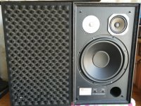
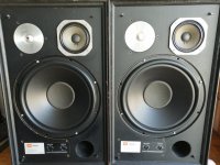
Hello all, I've been bitten by the horn bug and have decided to repurpose my 4 Peerless SLS 830669 - 12 in as the bass section of a Cornwall/La Scala/JubScala inspired build.

I have built a couple of speakers but am a neophyte and am hoping the collective wisdom of the group will point me in the right direction.

I have a few questions with regards to how I should set up the speakers.

The simplest route would be to build a simple box for them. Either ported or sealed. The specs suggest for a:
Sealed Box - 3 cubic feet, F3 of 40Hz
Vented Box - 4.5 cubic feet, 3" vent by 5" long, F3 of 30Hz

If I have 2 speakers per box do I keep to these volumes?
If not, how much larger do I make them?
A Cornwall is basically a big ported box with 2 horns stuck inside
(Which has uhhh....polarized the debate as to their appropriateness)

Following that train of thought, my concern is that horns are fast.
Will the above setup be too slow? Will it not integrate well?
Could I set the Peerless drivers up in some sort of folded horn arrangement? If so, what dimensions would I use? I don't mind big. Basically I want it all, deep fast bass and if the compromise is horn size, (without it taking up half my room) I can live with that. Let's say I'm willing to live with 2 fridges IF the performance follows suit.

My next question deals with horn driver suggestions.
Can I get away with a 2 way like a JubScala
(The best kind of crossover is the one that isn't there (0 problems with that one))

Suggestions for affordable compression drivers that could pull this off?

The nice thing about the Peerless drivers is that they will play fairly high up so perhaps this will let me find a suitable driver more easily.

If I decide to go 3 way, I've heard good things about the Selenium D250X midrange driver and Selenium D220Ti for tweeters.
Can anyone comment on their application in this instance?

Other suggestions?

What about waveguides?
Should one go letterbox shape, square, round? any models or plans I could base myself off? Do I make these of wood, fibreglass, purchase them?

As far as crossovers go, I haven't made up my mind yet. I may go active as I love the freedom it gives.

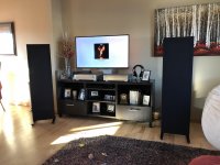
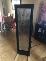
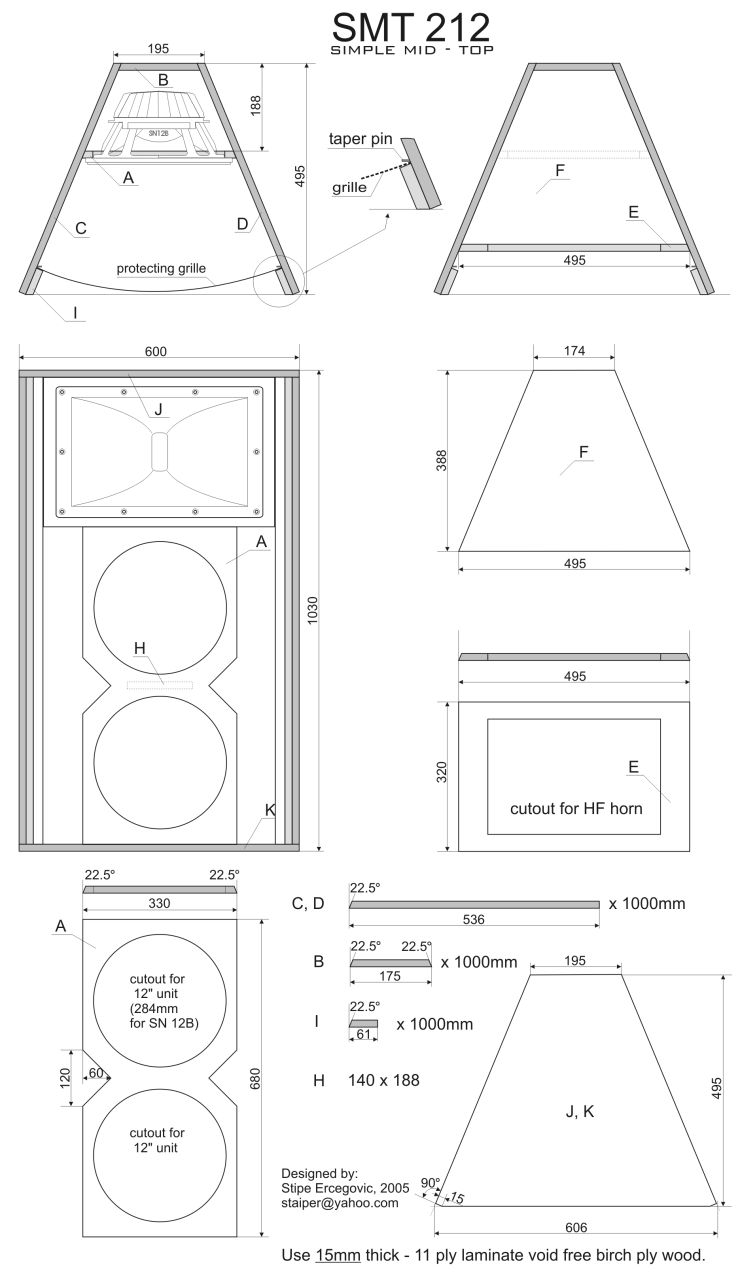
*Image is meant as a starting point. I will probably keep the bass units in their own enclosure and position the horns on top unless someone can give me good reason to put them inside the box.

Thank you in advance for all your great ideas.
Andre
SMT%20212%20TOP.jpg

Field coils & magnets, additive?

Ok, I'm currently drawing up a motor assembly...both a field coil design, and a permanent magnet design...and one that uses both, field coil AND permanent magnet. The goal is to have a maximum strength field as realistically possible. Upon further research, Neodymium is rated at 1.05 in permeability, virtually zero conduction of magnet fields...but, Neodymium in magnet form is "magnetized" ??? Is this zero magnetic field conductivity dependent on N & S polarity? I was thinking of using four 6" by 0.5" neodymium magnets as part of the magnetic conduction pathway...& now, since the material doesn't conduct, I'm going to have to redesign....Can both the field coil & permanent magnet work together to increase the magnetic fields?


-----------------------------------------------------------------Rick........

Vintage Tube Amp Hissing and Popping

Hello. This is my first post to this forum.

I have a little vintage tube amp that I run with an iPod into the RCA ports, and a pair of The Smaller Advents speakers.

I listen mostly to old jazz vocals or chillhop.

Recently my system has started hissing, popping and changing volume.

The amp has been gone over in the past by an instrument tube amp repair guy. I think some parts have been replaced by him. The tubes are some kind of new old stock I believe.

I am comfortable with wiring and soldering from my automotive pursuits. But I don’t know much about analog electronics. I would be willing to try to replace a cap or resistor, but not sure which one. Or I could reflow all the joints if that is a possible cause.

The large aluminum “can” on the upper side of the amp I understand to be a multistage capacitor for the power stage. I’ve seen where people replace that. Not sure if mine is original but it looks to be.

There is another smaller aluminum can on the underside of the amp (upper right hand corner in the picture) which does not look like something made recently.

I lightly tapped all the components up top with a pencil while powered up but did not detect any unusual sounds. I've poked around on the backside while powered off to see if there were any obvious loose connections and did not find any.

I could use some guidance if anyone has any. I really love this little amp. If I cannot figure something out on my own I will send it to a repair person.

Thank you.

amp%201-L.jpg


amp%202-X2.jpg

Mark Audio Alpair 10-m3 gold NEW

For sale 4 new units of this fullrange units from Mark Audio in gold color.Units never used and in original box.This units made for Unmonday company.I buy this for some project,but now I buy some Alpair 12p and will try with them.Price for all 4 is 200euro plus shipping.I will sell this als pair also if someone not need 4 pieced!Paying thru paypal or bank transfer.

Attachments

  • 20191229_130508.jpg
    20191229_130508.jpg
    653.6 KB · Views: 276

Upgrading USB to I2S card with Singxer C-1

The Singxer F-1 is a fairly widely known and highly regarded USB Digital Interface Board with the XMOS XU208 chip and it comes with a SPDIF output by RCA jack already mounted on the board and ready to go right out of the box. It was originally only available as a bare board, but a Singxer sourced clamshell case has since become available separately for it, and the F-1 is also now available available already installed in the case.

The sound quality of the F-1, in comparison to the older XMOS chip based designs, is a more immediate and clearly defined sense of the individuality and acoustical space around each instrument and voice in the recording, as well as a much tighter and seemingly deeper bass response.

The Singxer C-1 is a USB Digital Interface Board with the XMOS XU208 chip is essentially a Singxer F-1 design that is intended for hardwired connection directly to an I2S port. It is available from kitsunehifi.com fitted with either Femto AS318B Accusilicon clocks at $124.99, or with NDK / Epson clocks at $112.99. The C-1 boards are in short supply as most of the Singxer production is going into trying to keep up with the demand for F-1 boards and SU-1 units. I have had disappointing experiences with the China sales sources for Singxer, but good experience with kitsunehifi.com. I believe that kitsunehifi is the only Singxer fully factory authorized distributor in the USA.

I have a Singxer C-1 that I want to install inside my Eastern Electric Tube DAC Supreme, replacing the stock (older XMOS chip based) USB digital interface board inside. Eastern Electric documentation of the stock card pinout configuration is not consistent with the Singxer C-1 pinout configuration, and I am concerned that there may be some errors in translation.

I would appreciate it if other DIYers would check my following table of possible pinout matches to see if I have them correct, and suggest corrections if needed.

EE DAC Board→ Singxer C1 Board


MUTE : → 4 - AUDIO_MUTE

GND : → 1, 3, 6, 8, 10, 15 - UGND

X34 :→ 14 - FS0

DSD DSD out :→ 12 - DSD 64/128

X53 :→ 16 - FS1

X55 :→ 18 - FS2

GND :→ 1, 3, 6, 8, 10, 15 - UGND

LRCK : → 9 - IIS LRCK

DATA :→ 5 - IIS DOUT

BCK : → 7 - IIS BCLK

MCLK :→ 11 - MCLK OUT2

SEL : → 13 - DSD ON

SPDIF : → 2 - SPDIF_TX

GND :→ 1, 3, 6, 8, 10, 15 - UGND

MCLK1 :→ MCLK in

+5V :→ no connection ( 3.3V at pins 17 , 19)

Opinions on output filter stage for CS4398 needed please

Hi, I'm on my way repairing a Cambridge D500SE by modding it to a different DAC (the CS4391 has died and instead of substituting it, I'm going to use a CS4398 on a small diy board and modify and improve some parts of the original board so to connect it all). Now, I've been consulting the datasheets and the CS4398 has balanced outputs so the output stage is different, so I'm going to make an appropriate output stage with high quality opamps, now the question arises: is it best to stick to the design shown in datasheet (and evaluation board, I also had a look) for unbalanced outputs, or shall I consider some of the alternative circuits which can be found on the net? I got myself some service manuals of CD players which use this DAC and besides some discrete circuits, I also found the one I attached, which is from a Mcintosh player. I would only use the three opamp stages as I don't need balanced outputs. The passive components have completely different values than in datasheet. Maybe they are more adequate, as this is in fact a circuit for a CD player? While the datasheet output suggestion is a generic one? In fact having correct line level would be nice. On the other hand, datasheet output stage has been recommended on this forum a lot of times as seems to have correct filtering and is based on only one opamp stage, simplifying the design and which means audio signal will pass through less transistors, which is good.
So, what do you suggest? Unfortunately I'm no opamp design wizard so I can't really decide this alone... Stick with the datasheet standard suggestion or try the implementation from the mcintosh?

Btw, the original output stage in the cambridge player add an additional opamp stage after the output filter stage (which is done exactly like in CS4391 datasheet), I wonder if this is to get correct line level and all? So maybe I'd really need an additional opamp stage for this to get to correct levels, if I use the output stage of the datasheet of CS4398?

Attached goes schematic of mcintosch and original cs4398 datasheet output stage.

Thanks in advance for all suggestions.

Attachments

  • Captura de ecrã de 2020-02-28 14-33-05.png
    Captura de ecrã de 2020-02-28 14-33-05.png
    452.8 KB · Views: 285
  • Captura de ecrã de 2020-02-28 14-33-46.png
    Captura de ecrã de 2020-02-28 14-33-46.png
    237.9 KB · Views: 284

Sennheiser HD-570 Headphones.

I recently rebuilt a Sansui AU-5500 amplifier. I was testing it when I realized it was getting late and not wanting to **** my long-suffering neighbors off too much I dug out the old Sennheiser HD-570s that I haven't used for a long time. (Years) Wow! is the best description I can give, I didn't realize/remember just how good these things were? I realize there are better models but these did a very good job all the same! 😀

Niles SI-245 Weird Audio Sense Issue

Every once in a while, I will come across audio tracks, that this amp will just not "sense".

For whatever reason, those audio tracks, be it a YouTube video, song on the radio, or even the audio from certain games... doesn't matter how loud it is, the amp just times out and turns off.

Using it with my HTPC, having selected content paused on separate tabs, without any appreciable difference in source volume (while viewing VU on source device) - I can turn the amp back on, just by unpausing the sense-able media, even when it is set to the lowest perceptible level below that the of the content that times out the Audio Sense circuitry.

Sometimes I can get the problem track to trigger, but only by turning the source volume to max, or some random unknown frequency within the track is "sensed" by the amp. At no point do I ever adjust the controls on the amp. They are set to max sensitivity with master output dialed down a bit, to make it more sensitive to quieter source material, give more adjustment range at the source device, while not including the neighbors or the rest of my house in the currently selected program.

The most prominent offenders are clips from TV shows or movies uploaded to YouTube, with the occasional music video for good measure. The same video uploaded by another user might play just fine, but once a suspect track is identified, I can come back 2 years later and this amp still won't trigger on that specific source of audio content.

One suspicion I have, is that the content is mono, uploaded in stereo, with one of the tracks out of phase with the other... but I haven't tested this hypothesis yet.

Well... just tested it, turning the balance left or right the slightest bit, triggers the amp.. lol

Freud 1-1/2 inch roundover bit highly recommended

I just finished putting a rounded edge on my baffles. Although I have a lot of experience using a router in various woodworking projects, this is the first time I have used a router bit this large. It is the "Freud 1-1/2" Radius Rounding Over Bit, 1/2" Shank (Quadra-Cut) (34-140)".

I have never been disappointed in the quality of Freud bits. In the US and Canada, Freud bits are one of the higher priced options... not sure how they are priced in Europe, South America, Asia, Australia, etc... This bit is no exception... expensive but very high quality.

Notice the shavings I am holding in my hand. Rather than dust or fine chips, this bit made huge piles of shavings, similar to a block plane. (of course if I was cutting plywood or MDF, I would get dust and fine chips). The bit performed flawlessly. I was concerned about tearout on the end grain of the exiting side, but none happened. Cut quality was excellent.

Jim

Attachments

  • 20200214_122109.jpg
    20200214_122109.jpg
    353 KB · Views: 319
  • 20200214_123404.jpg
    20200214_123404.jpg
    202.1 KB · Views: 342
  • 20200214_123422.jpg
    20200214_123422.jpg
    311.8 KB · Views: 317

Recommend high quality capacitor for main filter

Seems like capacitor manufacturers phase out and phase in product lines. Among capacitors now on the market, are there any recommended high quality main filter capacitors? Long life. 105C. High ripple and low ESR. I know a lot of this stuff can be found on data sheets, but am wondering what particular caps folks have had good results with that meet these criteria.

System_D_MD, Class D is like chocolate

System_D_MD is a clocked design with post filter feedback, which uses parts of my private class D cook book.
Here MD does not mean Doctor of Medicine – it means Mostly Discrete.
I have audiophile concerns against irritating OP amps with large signals of the carrier frequency and decided to go for a discrete analogue input gain stage.
Further on I found that many integrated comparators have unpleasant jitter properties, which translate into poor noise figures in the audio band of the modulator. This pushed me to experiment with a discrete comparator in the triangle generator and the modulator as well.

Class_D is like chocolate. No need for fancy specials, but it has to be well balanced in its overall nature.
System_D_MD is intended to offer a pleasant balance of the properties below.
- Distortion
- Step response
- Noise
- Clipping recovery
- Carrier aliasing
- PSRR
The goal is to achieve reasonably good properties in all these fields, instead of pushing just a single topic to the extreme.

I have to apologize for the primitive way of scanned schematics and calculations, but during my spare time and hobby I enjoy to focus on the topic itself without winning a price for nice power point slides.


The listed references gave great inspiration to me and I am thanking the authors for their work:

Bruno Putzeys:
'The Bits In-Between. An EE's Guide to Survival Between Microphone and Voice Coil'
On the occasion of the 123rd AES Convention, Oct. 6th, 2007

Bruno Putzeys:
'Master Class, Life on the Edge, A Universal Grammar of Class D Amplification'
On the occasion of the 124rd AES Convention, May, 2007

Lars Risbo:
'DISCRETE-TIME MODELING OF CONTINUOUS-TIME PULSE WIDTH
MODULATOR LOOPS'
AES 27th International Conference, Copenhagen, Denmark, 2005 September 2–4

Lars Risbo and Claus Neesgaard:
'PWM Amplifier Control Loops with Minimum Aliasing Distortion'
AES 120th Convention, Paris, France, 2006 May 20–23


Stephen Cox:
'Mathematical models for class-D amplifiers'
School of Mathematical Sciences, University of Nottingham, UK
Presented @: School of Electrical & Electronic Engineering
NTU, Singapore, December 2009


Stephen M. Cox and Bruce H. Candy:
'Class-D Audio amplifiers with negative feedback'

Kaspar Sinding Meyer:
'Minimizing distortion in self-oscillating switching amplifiers'
Oersted DTU Department for Electric Power Engineering
Under guidance of:
Michael Andreas E. Andersen
Mikkel Christian Wendelboe Høyerby
Kgs. Lyngby, July 24, 2006


Nguyen Tranh T.:
Selfoscillating Switching Amplifier
Patent No.: US 7,221,216 B2
May 22nd, 2007

J. Lunze:
Regelungstechnik 1
DOI 10.1007/978-3-642-13808-9_8,
© Springer-Verlag Berlin Heidelberg 2010


Bruno Putzeys:
Selfoscillating Class D Amplification Device
Pub No.: US 2011/0068864 A1
March 24th, 2011

Vintage - JBL Horizon SPEAKERS Model L166 ; Eclipse woofers - $480 OBO - NH USA

or BEST OFFER
Sound good.
All drivers work well.
NO original woofers.
Aftermarket Madisound (Eminence) W1238R Eclipse woofers.

SPECS:

Eclipse, W1238R - Meniscus Audio

Madisound (Eminence) W1238R 12" woofer... | Audiokarma Home Audio Stereo Discussion Forums

Attachments

  • IMG_20190826_161118.jpg
    IMG_20190826_161118.jpg
    299 KB · Views: 459
  • IMG_20190826_161202.jpg
    IMG_20190826_161202.jpg
    162.4 KB · Views: 391
  • IMG_20190826_161206.jpg
    IMG_20190826_161206.jpg
    137.7 KB · Views: 373
  • IMG_20190826_161210.jpg
    IMG_20190826_161210.jpg
    138.9 KB · Views: 372
  • IMG_20190826_153720.jpg
    IMG_20190826_153720.jpg
    97.4 KB · Views: 369
  • IMG_20190826_161317.jpg
    IMG_20190826_161317.jpg
    344.7 KB · Views: 108
  • IMG_20190826_161738.jpg
    IMG_20190826_161738.jpg
    120.9 KB · Views: 86
  • IMG_20190826_161724.jpg
    IMG_20190826_161724.jpg
    151.6 KB · Views: 83
  • IMG_20190826_161355.jpg
    IMG_20190826_161355.jpg
    171.6 KB · Views: 70
  • IMG_20190826_161639.jpg
    IMG_20190826_161639.jpg
    144 KB · Views: 78

ISOTOP vs TO-264 MOSFET

This question is related to thermal relief or heat transfer between the devices. So lets look at some specs.

#1: ISOTOP - Pd:
Total Power Dissipation @ T C = 25°C: 500W
Linear Derating Factor: 4 W/°C

#2: TO-264 - Pd:
Total Power Dissipation @ T C = 25°C: 520W
Linear Derating Factor: 4.16 W/°C

If adequate cooling is in place for both, would there be any difference in heat dissipation for these devices.

Problem with hifonics bxi 1100d

Hello. I am the owner of hifonics bxi 1100d, the problem is that the green LED is off. It lights red and then goes out at this point the amplifier should go into standby but nothing else happens after checking there is no voltage at tip41c. There is no diagram for this amplifier but the construction is similar to the bx1500 model, no voltage on Q100, so there is no relay control

Attachments

  • bxi_schema (1).png
    bxi_schema (1).png
    162.5 KB · Views: 101

Enclosure for a 3.25" driver

Hello,
I just took out my old pair of mini speakers from an old JVC UX-2000 system.
Each speaker is tiny with only one 3.25" driver and a small port behind, but the sound is lovely and enjoyable.
I am just thinking of putting the drivers in a new enclosure, but i don't really know the science and math behind all the complex calculations.
I am not looking for big sound or deep bass, just want them to sound more like a pair of bookshelf speakers. Probably considering letting them firing at 45 degrees like the Shahinian Larcs / Elf or the Neat Iota Alpha.
Anyone have tried building a pair of full range speakers with just 3.25" drivers? Maybe I can still some ideas in terms of the enclosure volume and port size.
Thanks.

frequency amplitude R//C serie correction

Hi,

I'm looking for hat is correcting 1R//10 uF in serie on the tweeter signal please ?

The tweeter is a 4 ohms nominal impedance (3.5 measured at voice coil) and XO is a LR4 at 2700 hz. this RC is between the two coils.

I looked for on line calculators but found at best RCL notch spreadsheet.

I assume this RC in serie with the signal gives a bump a the bottom or middle frequency of the tweeter to match the mid driver at corret spl but I can't find the frequencies windows involved by these RC values.

Are you please aware of a link about such frequency network correction please ? Bagbys's excells ?

Which small class A P-P design to build?

Hello

I'm wondering if I should try out the benefits of class A operation. The thing is, if I decide to keep what I build, it needs to be medium powered and moderately efficient, which implies P-P operation.

One special case is Douglas Self's class G design, of which I have heard that it's possible to run the lower supply voltage in class A.

So basically I have two and a half questions:
1. Are there any nice and small passively cooled class A P-P designs with +/-16 to 25 V power supplies?
2. Has anyone built the Self's class G amplifier, and then run the smaller supply in class A?

Tube tone control baxandall

Hello folks,

I was looking for a diy tube preamp project, and found out this one which i think could be even better, but im newbie on this and need some opinions about.

I found a tube tone control baxandall. I want something that gives me some tube coloration and de bax filters is a plus coz i can shape sounds even further.

This pcb is being selled on eBay and Amazon. The sellers says its a good quality circuit, made to be built with good components.

I want to hear from u guys, what u think about this project. Can It give me some coloration + bax filters with a good audio quality?

Thanks,

61kF14kg7GL._AC_SL1500_.jpg


An externally hosted image should be here but it was not working when we last tested it.


images

3FE25-8 pipes

Hot off the press this morning.

Faital Pro 3FE25 8ohm

Volume 3.4L (0.12ft3) +or- (optimum for driver according to what I found on www)
100mm pipe with just short of 40cm overall height

Melamine sponges behind the driver.
No other stuffing.
1" vent on back (the end of pipe is cosmetic - it is not really a port - I will try it without as well which will open the vent to 1 1/3")

Hit the plumbing section because I can't get foam core board in Vientiane (would have preferred to make 0.4x Karlsonators) - these will do for now! Will have to try a BSC at some point as they are a bit sibilant at the very top and the convenient thing is that the bottom cap is threaded so I can easily get in there to tweak. (Nephew coming to visit in April so will use him to courier parts)

I welcome any comments/suggestions how to tweak these to get the best sound.

Have a great day. Stay healthy.

Attachments

  • pipes.jpg
    pipes.jpg
    585.2 KB · Views: 333

Infinity Kappa VS Morel (Tempo?)

Hi

I own A morel Maximo (compo).
Al tough I read that maximo gives A great VFM I still I want to add more depth (hope it the right term) into the front stage And I feels that there not much of this depth.

I heard good things about Kappa series!

I am A moderate listener...also At home I have good - but entry level system (pionneer 921+Polk Audio S20 Signature + S15).

So I want A good ENTRY level speakers and thought about Kappa series of Infinity.
What do you think?

What about Morel that would be the "parallel" of them to Kappa 62IX or 60.11CS?

P.S:
1) In the Infinity Kappa 60.11CS - in title it's 6-3/4" but on description its 6.5".
So...what is it?
2) Is there A noticable advantage for A component sp over coaxial?

Thanks so much!

Restoring highs - dope?

Hi Everyone, first post but thanks for all the info I've soaked up already.

I have owned a pair of B&W DM7-mkIIs since about 1987. I recently pulled them out of retirement and they still work - quite well - except they have lost their sparkle - the highs aren't quite there, the sound just hits a ceiling (even before my aging ears hit theirs!).

I initially thought I should re-cap the crossovers, but someone very knowledgeable told me that the caps used in these crossovers don't deteriorate with age.

Instead, he said that the tweeter diaphragm has probably got dirty, dried up and become semi-permeable so it is not delivering air as well as it should, and it should be re-doped; it sounds like he means re-coated with dope to "seal" the surface.

Does that sound right? And if it is, what would I use? B&W describes the tweeter as "multi-filament polyester weave dome." And if that isn't right, what should I try? Is re-capping the solution?

If I can recover the highs, these speakers might still compete with the pair of new, pretty good speakers sitting next to them.

Thanks!

Citronic dimension 4 power amplifier switch not working in stereo

Hi all, firstly any guidance and information will be much appreciated

I have a dimension 4 amplifier that I just bought.

It is in 'as new' condition except the switch on the front only works in both channels in mono, when I switch it to stereo it only works in one channel and the other channel is dead.

I actually prefer to use this amp in mono yet still want the unit working fully as it's in great condition.

So far I have:
Used contact cleaner in the switch

Reflowed the switches and preamp boards solder joints as it's the terrible lead free solder which is the worst solder I've seen, really just bubbles and pops

Tried both jack and XLR inputs and checked the buttons on the back are not in bridge mode or anything

My question is, is the switch faulty or could it be another issue? I've not come across an issue like this before

does DC loop feedback in a cascade feedback pair mitigate turn-on/off thumps ?

does DC loop feedback in a cascade feedback pair have any effect (good/bad/neither) upon turn on/off transients in a preamp with no timed relay protection?

what are the bad points of applying DC loop feedback in the circuit below?

around 45 years ago I accidentally turned off a Citation IV preamp connected to a Citation 12 power amp - the turn off transient blew 4 Dynaco A35 woofers.

Van Alstine had AC feedback in his "Super Pas" mod hi-level 12ax7 stage, photoflash caps in its power supply and it was well behaved w, my DH200 - not the best sound but could be switched on and off without destroying speakers and perhaps the amp itself.

for a phono preamp these days, I'm more interested in a bare bones version of Stu Hegeman's Citation I/IV and with an anode follower hi-level stage.

TbbnIp8.jpg

Ground Zero PLUTONIUM GZPA 1.8000D Blowing output fets random

Hi all!

I have been working on the amplifier for a couple of days and have a problem with starting it "cold" as soon as I turn it off. Starting it for 5-6 seconds wouldn't oscillate twice out of ten. if it has a final stage (IRFP360LC) then it will unfortunately shoot you.
I have already replaced IR2113 on it. If you go then you can unwind completely, do not collapse. What can cause it?

https://im9.cz/sk/iR/importprodukt-orig/cc1/cc145ef3c246461aebb669e5334fb2bf.jpg

Looking for a starter diy project

Hey guys,


I am a student studying commercial music (this is my first post on this forum), and I am in a class where I need to do a diy project.


The project simply has 2 requirements:

-At least 75 soldering points, preferably thru-hole, as I am totally new to the realm of audio electronics and soldering.
-Obviously must produce or process sound


After doing a little bit of digging, I have started to like the idea of building a tube headphone amp. Know this is where you guys can possibly jump in and give me some advice, help, direction, etc.


I've found some simple kits on ebay/amazon/etsy (I'll link them below), but I'm wondering if y'all might have some links to other places for more ideas, or even other ideas for what I could potentially do with the simple requirements of the project. I'm looking for something ideally under $50. I'd like to be able to take this project a bit further in the future, and potentially make modifications to existing parts (i.e. adding higher quality matched tubes), because I don't just want this to be something I build and do nothing with.


I'd appreciate any advice/links on kits and making modifications that y'all can share!


Tube Amplifier AMP Audio Board Pre-Amp Mixer 6J1 Hifi Valve Headphone Diy Kit | eBay


https://www.ebay.com/itm/6J1-Valve-Pre-amp-Tube-PreAmplifier-Board-DIY-KIT-Headphone-Buffer-Case-AC-12V/332295637972?hash=item4d5e5d0bd4:m:mlER4ksGwR-dVHtU-YfgQJQ


Newest 6J1 tube preamp amplifier board Pre-amp Headphone amp 6J1 valve preamp | eBay


6J1 DC12V Valve Preamp Tube Board Headphone Amplifier Board+Acrylic Case DIY Kit 818692309840 | eBay
Projects by fanatics, for fanatics
Get answers and advice for everyone wanting to learn the art of audio.
Join the Community
507,774
Members
7,888,063
Messages

Filter

Forum Statistics

Threads
406,220
Messages
7,888,063
Members
507,774
Latest member
pete2000