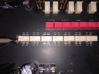
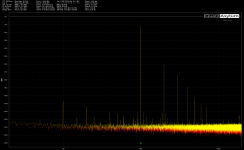
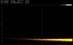
I've been working on a preamp design with a log stepped attenuator and I've come across a strange problem. Overall performance is good except when it's set to -0.5dB or -32 dB (when the stages are set 1000000 or 0000001).
When I started to probe the circuit I found that the distortion disappeared as soon as the probe touched the signal circuit.
Any ideas what's going on? It happens even when I have the probe BNC disconnected.
The attenuator is 500Ω with 7 stages (1/2, 1, 2, 4, 8, 16, 32dB) with an OPA1612 buffering the input. I originally thought that I might be overloading the buffer op amp but the result is the same with lower input signal voltages.
Ideas appreciated.
Thanks.
Attachments


A quick thought would be the capacitance of the probe is killing some extreme HF instability somewhere. A finger judiciously applied to various areas might get a handle on it.
I thought the same... I've tried poking around and putting a 10pF across the same points but nothing.
I wonder if the long traces are causing a problem somehow. A small series resistor at the opamp output... well you know how it goes 🙂
Might be worth trying playing around with the noise gain of the opamps by adding a resistor and series cap between the two inputs.. Begin with just the resistor, it won't alter the signal gain.
Its a case of getting an idea where in the chain the problem begins, at least to begin with.
Might be worth trying playing around with the noise gain of the opamps by adding a resistor and series cap between the two inputs.. Begin with just the resistor, it won't alter the signal gain.
Its a case of getting an idea where in the chain the problem begins, at least to begin with.
Good plan... the traces are quite long and I should have put 50Ω on the op amp output. I'll see if I can find a way of inserting one in the circuit. I've become so reliant on probing the circuit to fault-find this one's thrown me because the fault disappears the second the probe makes contact.
Thanks.
Thanks.
Try the circuit with only one op amp at a time, to see if just one of them is causing the problem.
They do each have bypass capacitors? Does the input op amp actually have 27 ohm feedback resistors?
That is way too low for the first op amp's output, plus there's the resistor network loading in parallel.
They do each have bypass capacitors? Does the input op amp actually have 27 ohm feedback resistors?
That is way too low for the first op amp's output, plus there's the resistor network loading in parallel.
Last edited:
Try the circuit with only one op amp at a time, to see if just one of them is causing the problem.
They do each have bypass capacitors? Does the input op amp actually have 27 ohm feedback resistors?
That is way too low for the first op amp's output, plus there's the resistor network loading in parallel.
Hah, no sorry I quickly put together the circuit in Tina TI and copied R1 without changing the value, R16 & 17 are 1k. 100nF x 2 on both op amps as close as I can get them to the supply pins.
I'm up for taking the output op amp out of circuit but wouldn't mind trying a few less invasive things first.
Thanks.
Does the distortion show up at the output of the resistor network?
How about at the output of the first op amp?
How about at the output of the first op amp?
Last edited:
I reckon you need some resistance in series with OP2's input. 50-100 ohms tops. Clearly the problem occurs when source impedance at this point is particularly low. It's a problem particularly afflicting low-noise BJT inputs. BJTs do not like predominantly inductive source impedance, their beta(f) curve tends to turn it into negative impedance at the emitter.
BTW, are you sure about the 27 ohm resistors in OP1's feedback network? Is that an AD797 class part, at rather low levels (maybe 1 Vrms tops)? This would be the only constellation where these would make sense to me. Opamps certainly aren't built to drive loads like that at any kind of substantial level (use a buffer and multiple resistors for super wide dynamic range applications). With values this low, some attention to shared ground resistance may be needed as well.
BTW, are you sure about the 27 ohm resistors in OP1's feedback network? Is that an AD797 class part, at rather low levels (maybe 1 Vrms tops)? This would be the only constellation where these would make sense to me. Opamps certainly aren't built to drive loads like that at any kind of substantial level (use a buffer and multiple resistors for super wide dynamic range applications). With values this low, some attention to shared ground resistance may be needed as well.
Thanks for all the pointers, the distortion seems to be coming from OP1- I'll confirm this evening. OP1's feedback network resistors should be 1k (mistake on schematic).
Series resistance seems an obvious thing to try, I'll see what I can do without affecting the attenuator operation (and without wrecking the board).
Series resistance seems an obvious thing to try, I'll see what I can do without affecting the attenuator operation (and without wrecking the board).
Oscillation or instability is immediately suggested - an RF spectrum analyzer with a E-field probe would be one way to track it down non-invasively.When I started to probe the circuit I found that the distortion disappeared as soon as the probe touched the signal circuit.
Try 10pF in parallel to R16, that's possible to tack on top temporarily. What's driving the non-inverting input of OP1?
Thanks Mark, 10pF in parallel with R16 did the trick... plus I can just stack the components without butchering the PCB, so result all round.
BJTs do not like predominantly inductive source impedance, their beta(f) curve tends to turn it into negative impedance at the emitter.
This!!!
As the original poster suggested add say 50Ohm resistor as close as possible to the opamps' inverting input to isolate it from external stray capacitance... Just like Grid stopper resistors on Tube Grids / Mosfets Gates 🙂
It's a bit unusual for input capacitance to push things into oscillation with a 1k / 1k feedback network, but whatever - if it's fixed, it's fixed. You normally don't see much in terms of parallel compensation caps until Rf approaches 10k. Perhaps the layout has plenty of groundplane under the inverting input pin?
The problem is fixed in all cases other than when all attenuator stages are bypassed. I think adding 50Ω in series with OP2 input (or the attenuator output) is a sensible thing to try. At the moment I've just just set the minimum attenuation to 0.5dB in software which is not really a problem.
I'd like to understand what's going on but also don't want to do anything too invasive to the PCB as it's 380x225mm and it'll take a bit of work to recover some of the more expensive components if I mess up (and I often do).
This is a four layer board (1 Signal, 2 AC Gnd, 3 Power, 4 DC Gnd) which is a consolidation of a number of (tested) designs onto one PCB. The only differences are that previous versions have used a 1k attenuator, input, attenuator and output circuits were on separate boards and I have 2x gain on the input.
Thanks for all the suggestions.
Yay! I wasn't actually very confident that that was the issue ...Thanks Mark, 10pF in parallel with R16 did the trick... plus I can just stack the components without butchering the PCB, so result all round.
- Home
- Source & Line
- Analog Line Level
- Weird Attenuator Problem