For Sale Tubes for sale

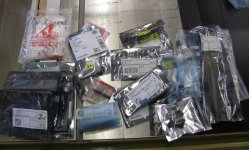
Some tubes for sale 🙂

4-Jan RCA 12AY7 tubes NOS $50 each plus shipping

6-Telefunken 12AX7 smooth plates ANOS $75 each plus shipping SOLD

2-MWT U54 rectifier NOS $250 each plus shipping

2-GEC U54 rectifier used test good $250 each plus shipping

RCA 5R4 NOS $25 each plus shipping

2 pairs of 845B tubes one Russian one Chinese $125 per pair

5931 rectifiers $50 each plus shipping

Attachments​

  • IMG_5036.jpeg
  • IMG_5037.jpeg

  • IMG_5040.jpeg

  • IMG_5041.jpeg
    IMG_5029.jpeg

  • IMG_5051.jpeg

  • IMG_5052.jpeg
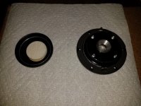
Amperex 7119 “D” getter $150 pair plus shipping

2 pairs-Amperex 7119 ring getter $100 pair plus shipping

Tungsol 5687 tubes $20 each plus shipping

14- RCA 5687 tubes $25 each plus shipping

Attachments​

  • IMG_5093.jpeg

  • IMG_5098.jpeg

  • IMG_5099.jpeg

  • IMG_5104.jpeg

  • IMG_5112.jpeg

  • IMG_5113.jpeg

Attachments

  • 1689740469334.gif
    1689740469334.gif
    42 bytes · Views: 62

PA Subwoofers to use with EV ELX200-15p Speakers

Hello!

I'm in the process of buying or building a pair of subs to use with the EV ELX200 15inch speakers I recently bought second hand.
The speakers can be replaced in the future so, for the subs I don't mind to go a little overkill.

I think it would be better to build instead of buying because of my requirements:
  • Max weight 35Kg
  • SPL 134db or more
  • Frequency response starting at 30hz (-3db)
  • Size, under 24inches (bigger side of the box)
  • Active would be great, but a passive will be preferable due to cost

I don't even know if this requirements can be meet...
A tried and tested design would be ideal... But I'm open to suggestions.

Woofers that were recommended to me (and are available in Europe):
  • B&C Speakers 18DS115, 4 ohm, 18 inch
  • Beyma 21LEX1600Nd, 8 ohm, 21 inch

Buffalo 3 SE Pro 38 no sound. Help!

it was working fine las Saturday. I fired it up today and no sound. Checked the voltage output from the Centaur ps, 2 v only, do I thought this might have been the culprit do I proceeded to install the Placid HD supply, checked it’s output, 5v, ok let’s see. Well it does not work either. No sound. Any suggestions? Is the dac board dead or any of its trident boards? Because there are no leds to be seen it is difficult for me to ascertain the damage. Any suggestion will be appreciated. Thanks

Pioneer SA 9500 Left Channel Cutting Out

I recently replaced some transistors on it with some advice from this community, but now I have a new problem, or, more accurately, an old problem that I forgot it had because I hadn't used it much for a good while before the transistor job.

It will play perfectly for 30 seconds or so before the left channel fades to almost nothing. After several minutes, it might come back up, but fade back out again after around 30 seconds. It does this on all inputs and whether or not the tone controls are on.

I was checking through all the mechanicals to see if I could either cause or reverse the behavior (mostly just moving things around hoping to find a bad solder joint or something), but nothing I tried seemed to change it except for one thing - on the pre/power switch, if I bridged the "normal" (meaning not separated) and common contacts, for even a split second, the left channel would immediately kick back on to full volume and go for a minute or so before cutting back out. So thinking there was something wrong with the switch, I connected the pre in/power out jacks on the outside, but the amp exhibited the same behavior. Even more odd, it didn't seem to matter which position the switch was in. Bridging those contacts would still cause the left channel to kick on and eventually go back out.

I considered just soldering jumpers on the switch to basically set it permanently in the "normal" position, but this seems like a bad idea if I'm not 100% sure that the switch is the issue. I'd think that if the switch was at fault, the channel would only work while I had those contacts bridged and not continue to work for a period of time afterward. And it would work with pre in/power out jacks connected.

I should also mention that I cleaned up the protection relay contacts with 800 grit sandpaper and contact cleaner, so I don't believe the problem lies there.

Anyway, I'm now unsure of how to continue troubleshooting the issue.

Ultra-Compact (Sub 2-inch) Super-Loud Driver for Voice / Speech

Hello everyone.

Seek your inputs on choice of loudest possible driver for voice / speech applications which can fit in a sub 2-inch diameter circular cutout.

Weather and ingress protections are highly desirable due to nature of the application.

Presently, have homed on to the following: -

https://www.parts-express.com/Visaton-PL5RV-1-5-8-Full-Range-Driver-4-Ohm-292-636?quantity=1

However, cost being no object, want something which can go really really loud.

Threshold 4000 repair. Need some help.

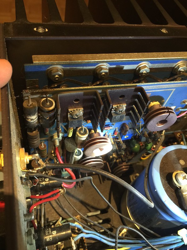
A friend gave me a Threshold 4000 that was in need of help. Both channels seem to be shorted. Here is the worst one.

16883706582_a52dc1b314_c.jpg

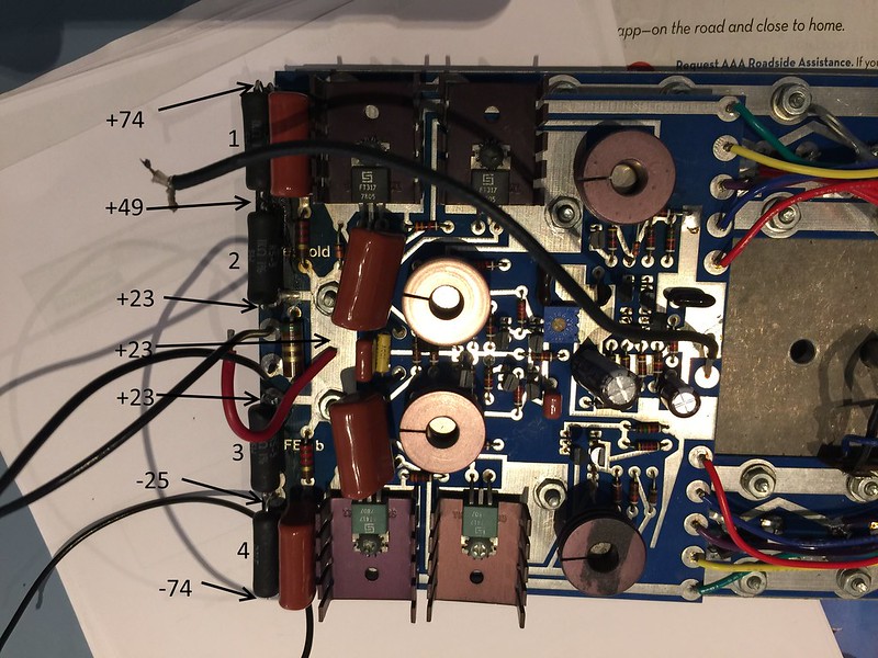
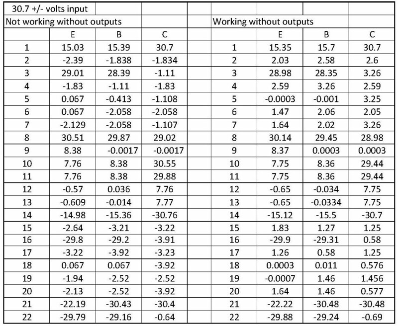
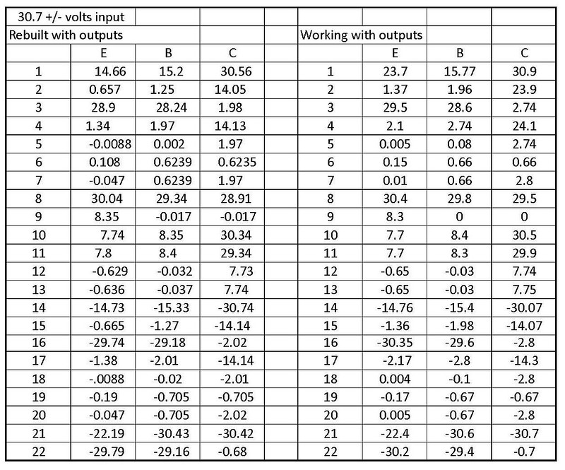
Jon at vintageamprepair.net help me with the output sub. Here it is back together. There is still something not right. See the voltages in the picture at 120volts input. The 1k resistors number 3 & 4 get hot pretty quick.
16700442778_435520f777_c.jpg


What should I check next?


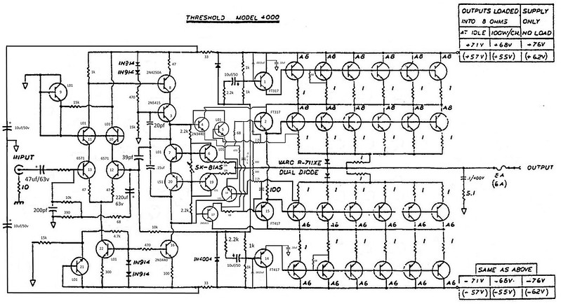
This schematic shows the differences I have seen on my board so far. I moved it here from post 17 so I can update it.


16972440635_6839c1608f_c.jpg

400


16736383604_f532085abf_c.jpg
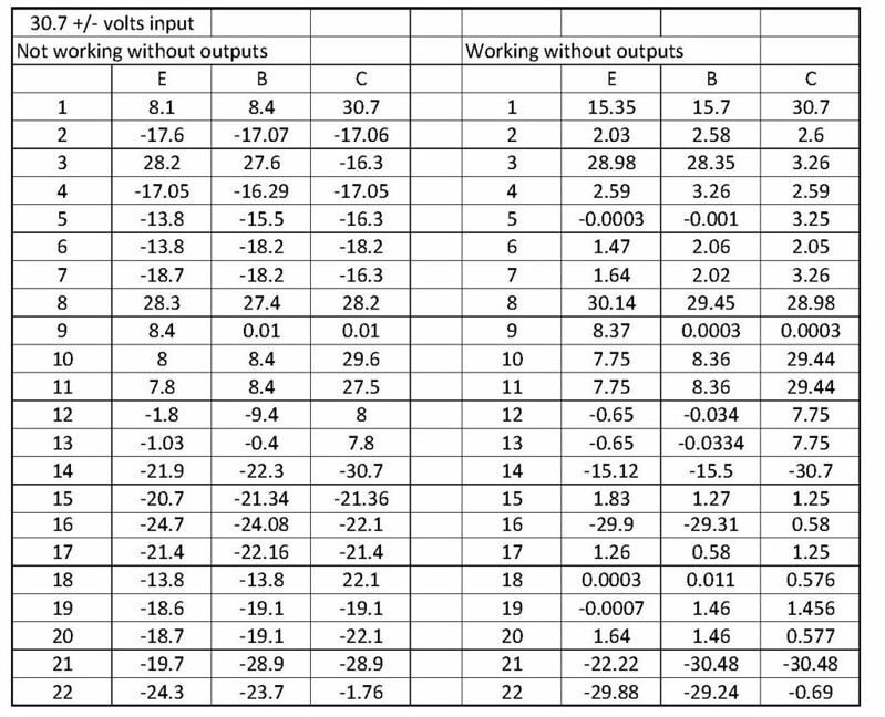
Volts30 with working no outputs

17250328458_4739bf00f2_c.jpg
diode fixed

17577153321_3fae918597_c.jpg
Volts30 with rebuilt

FET switches

I have an old vintage tape recorder that uses N-channel FET switches (2SK362) and P-channel FET switches (2SJ104). These are now obsolete, and I was also wanting an FET that had lower on-resistance----currently the N-channel devices are 80Ω and the P-channels are 40Ω. Can anyone suggest alternative replacements? These are both in a TO-92 package.

What cabinet design best for this unusual subwoofer? Bass reflex, passive radiators, corner-horn....?

Driver has Fs 54 Hz but stays above 95dB down to 27 Hz, where it drops off sharply. Is is doable for the right cabinet to maintain the response down to 25Hz? or what would be the challenges to do so? Could it go down to 22-23? Or, even if put into a good cabinet, will the response drop off well before it gets to 27? That's a large difference between 54 and 27Hz, and I know its unusual, so has anyone encountered such an issue before? An Audiogon forum member suggested I ask this question here. Please help as I'm sure looking forward to ideas and recommendations.

Small Sub with 10" Ciare HS251 -- some questions

Hello there,

I have now received a pair of the Ciare HS251 subwoofers. They look nice, magnets are bigger than I expected. For now I stuffed them into a big box, connected to an amp driven with a LSP crossover plugin up to 110 Hz... just to "burn" in a bit.

For my box calculation I used Unibox by Kristian Ougaard. It's available on Charlie Laub's website

I ended up with a 72 liter box with a port of about 170mm length (inside diameter of port is 74mm). That's a bit long... not sure if that should be a concern. I decided to put it onto the back of the box. My concept for this built is to use corner blocks and also blocks along some length as seen here:

shot-2023-07-05_01-45-36.jpg


I have build a huge 2 x 15 bass instrument speaker like that and it worked out great... less trouble clamping etc.

Anyway, my question is if this port length seems odd? I also have the program "Basta" installed, and there I am getting quite a different length suggestion (82mm).

Any idea why these values don't line up?
Any suggestions regarding the box design? There will be two of these... placed behind my desk.

shot-2023-07-05_01-51-58.jpg


Thanks 🙂

Audioquest Niagara 1200 Noise-Dissipation System with Pass Labs INT 25

Hello everyone. I'm currently uncertain about whether I should invest in an Audioquest Niagara 1200 Noise-Dissipation System. I brought this unit home to test its impact and I believe I can perceive enhanced clarity, improved microdynamics, instrument separation and so on. However, I'm cautious about potential biases in my hearing and the influence of psychoacoustics in this situation.

I'm interested in hearing from anyone who has tried a similar setup with Pass Labs equipment. Considering the specifications and the inside parts of the Audioquest Niagara 1200, do you think it has the potential to negatively affect the music signal?


SPECIFICATIONS
  • Level-X Linear Noise-Dissipation Technology: More than 19 octaves of AC differential filtering (20kHz–1Ghz in excess of 24dB) with linear response, optimized for varying line and load impedance
  • Patented Ground-Noise Dissipation (All outlets): 2 banks of direction-controlled ground-noise dissipation
  • Non-Sacrificial Surge Protection: Withstands multiple AC surges and spikes up to 6000V/3000A without sustaining damage—sonically non-invasive
  • Maximum RMS Input Current: 15 Amps (RMS)
  • Outlets: Source (5); High-Current (2)
  • Dimensions: 19.4" W x 3.2 H" x 7.5" D
  • Weight: 18lbs. (US); 8.16kg.

Audioquest-Niagara-1200-4.jpg


Audioquest-Niagara-1200-7.jpg

Rega DAC-R - Weak Right Channel

Following up on my original thread posted back in 2022 : thread

Context:
I got a Rega DAC-R second-hand from someone i trust didn't have, or at least didn't notice, any issues with the device prior to shipping it. It turns out it looks (and sounds) like it has significant channel imbalance (see measurements below).

My Goal:
I'm trying to find an obvious issue with this DAC, as i suspect it might be a poor connection or faulty passive component that could've happened during transit or due to age. If it is not, I will send it for repair, but i figured i'd try to give it a try before i do so as it will be costly to the point where i'd rather replace the DAC considering a chip replacement might be more than what i paid for the DAC.

What could help me:
Any guidance in terms of diagnosing possible issues without sophisticated testing equipment. Any knowledge on this particular device or DACs in general (if it is a common issue etc.) as it will be my first attempt at fixing or at least diagnosing a DAC.

Note: I have no expectations, and will provide any and all necessary pictures or measurements I can take as I would be grateful for any help 🙂. I see this as a learning experience if nothing comes out of it.
Thank you to anyone taking the time to reply to this, I'm taking it apart and looking for any visible issues tonight and will update with anything I find worth noting.

Measurements:

Dac-r + brio-r :
Left: 2.88v
Right: 1.99v
Difference: -0.89v / ~ -31%

Dac-r + linn:
Left: 2.84v
Right: 0.94v
Difference: -1.9v / ~ -67%
(Measured at amp speaker output. Issue persists with various amps. Amps are fine with a different DAC.)

LTspice output impedance current drive amplifier

Hello everyone,

I'm currently striving to plot the output impedance of my amplifier on LTspice, assembled with a current drive or mixed mode feedback configuration.

I've tried Elliot's method here : https://sound-au.com/articles/current-drive.htm#s5 but it doesn't seems to work for me on my design, my amp becoming unstable when unloaded.

Any further ideas ?

For Sale Crown XLS2502 & LaVoce SAN184.03

For sale here is my trusty crown XLS2502 amplifier, been a great amp but moving to a more compact Hypex plate amp for my next sub build so have no use for this. Have got a box so shipping is no problem.
£375 plus shipping.

Also for sale is a brand new LaVoce San184.03 driver with 100cm long 6” cardboard port for a ported subwoofer build.
£350

Liam

Attachments

  • E51FC906-5A6D-406B-8B13-C40DAA4871EF.jpeg
    E51FC906-5A6D-406B-8B13-C40DAA4871EF.jpeg
    515 KB · Views: 81
  • 5BE07BA7-EE96-4CDB-8FFF-19770D15976A.jpeg
    5BE07BA7-EE96-4CDB-8FFF-19770D15976A.jpeg
    472.8 KB · Views: 78

Potentiometer from 5k to 10k

I'm working on a Sony XM-1600GSD and the Filter said it needs a 12 pin 5k and I cannot find that anywhere from the USA to China. I stuck a 10k in its place would that be ok? I got the amp with rusted pots so I’m not sure how it sounded but after changing the Gain (6 pin 5k have it), Low Boost (6 pin 50k have it) and Filter (12 pin 5k did not have changed for 10k) the sound comes out playing very nice but the volume is very low to where I turn the stereo completely up and the gain all the way up and it’s like playing at level 2 maybe. Do you think the 10k might have done that? Remember I did not get a chance to hear this amp before I changed the pots. What might be the problem or where should I look? Thanks

Attachments

  • IMG_20230715_182516.jpg
    IMG_20230715_182516.jpg
    704 KB · Views: 91

MA1070P does not work with I2C when BCLK is enabled

Hello.
I am (un)happy owner of I2S amplifier board from aliexpress:
https://aliexpress.ru/item/1005001623757092.html?sku_id=12000016865437219

When I communicate over i2c protocol, I faced with issue that if i2s is enabled (BCLK and MCLK are enabled) i2c does not work.
esp32 returns error timeout.
I checked with logic analyzer - really, no any reply from MA board.
If I disable BCLK - I2C work successfully.

Is it bug, or feature of MA ?

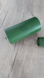
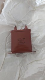
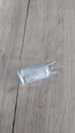
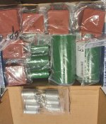
Sey of USSR NOS Capacitor

For sale the following set of russian capacitor NOS. Never used.

2x K75-10 (~PIO) 1000V 50Hz 1uF
6x K75-10 (~PIO) 1000V 50Hz 0.22uF
8x MBGP-2 (PIO) 1600V 0.25uF
7x K50-20 (ELECT.) 25V 200uF

PRICE: 60€ Paypal or Bank Transfer.
Shipping not included.

Attachments

  • 20230625_094743.jpg
    20230625_094743.jpg
    329.6 KB · Views: 130
  • 20230625_094747.jpg
    20230625_094747.jpg
    229.4 KB · Views: 114
  • 20230625_094850.jpg
    20230625_094850.jpg
    144 KB · Views: 113
  • 20230625_095048.jpg
    20230625_095048.jpg
    220.9 KB · Views: 118
  • pack.jpg
    pack.jpg
    470 KB · Views: 91

My new project sounds awful with good drivers

Hey, its my first post although I often was browsing this forum. I ask for help because this drives me crazy and I think I tried everything I could think of.

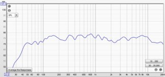
I got 18l enclosure where Im using dayton ES180TiA 7" and SB acoustics sb26stwgc with the crossover that graph is below. I tried different dampening amounts from non to filling it whole with rockwool. I tried sealing the enclosure to a level where max xmax 10-20hz wont make any sound leaking. I tried moving them around, different dampening material, different room, dsp etc and they sound awful. Highs sound quite decent but midrange sounds weak and bass is also awful. It sounds worse than emotiva b1 or even audioengine a2+ or kef iq7's. They sounded quite good in open baffle expect that they couldnt even hit 250hz and I had to do excesive dps and cross them with sub but they sounded really good then. Right even tho they measure like the green graph below in room they sound like a 50usd speaker or something.


1680977391552.png
1680977986146.png

Attachments

  • 1680977900712.png
    1680977900712.png
    63.3 KB · Views: 235

Popping sound in X1 Preamp channel

Hi

I recently purchased a X1 preamp from a USA dealer. Full disclaimer I had it shipped to Australia and had the voltage swapped to 240v which is a 5 minute job with the X1s multiple primary transformer. This unit has been recapped by Pass Labs in recent years so I didn't think much could go wrong. Upon plugging it in it instantly started to make a popping sound in the right channel when taken off mute. I haven't listened further as I don't want to hurt my speakers or amplifier, I just moved house and decided to give it another go but the noise remains. Outside of the popping sound it appears to work normally.

Any ideas on the potential issue and maybe some further checks I could do?

  • Locked
Sony VFET Amp boards - Papa group buy

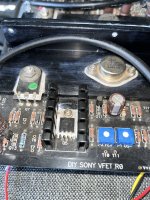
With a big heart I am letting go of my Sony VFET amp boards fully built along with the aluminium profile which I got in 2017 group buy kit thanks to Papa. I am now a fan of the SIT R3 amp and this one is not being used with the cabinet being repurposed for another amplifier build. I know there are many big fans of Papa's VFET amp so I hope another member will enjoy this amp for many years just like I did for many years. All genuine parts from either Mouser or Digikey or Newark have been used. Power mosfets are closely matched IRFP devices from alweit member of Israel when he was running his eBay store.
This was kept in safe storage away from moisture/heat etc. This is the essentials kit batch 3 and the matched VFETs from Papa himself 🙂

I will pack securely double boxed and shipment to lower 48 states. PayPal fees and shipping extra, make me an offer via PM.

Price $650 including US shipping.

Thanks

1685941633264.jpeg


1685941679177.jpeg

Attachments

  • 1685941698128.jpeg
    1685941698128.jpeg
    688.3 KB · Views: 197

Finally! Bought a pair of real Danley

Good things comes to he who waits – well sort of
-- Or –
If you can’t afford a new Corvette, what’s wrong with a late-model Camaro?

After years of being a Danley fanboy, much recounted on this very site, I have finally bought a pair.

Not the coveted SH50. Nor the perhaps more appropriate SM60F. It’s worth mentioning that the latter have nearly doubled in price in the past several years, pretty sure. OK, I’m such a genius, why didn’t I buy a pair years ago? I had the funds. But even worse – in a way – I snagged a pair of very beat up Yorkville Unity U15 in about 2015. Slightly tweaked, these have provided excellent sound for eight years. Even the best Danley, I rationalized, might only be an incremental improvement over what I had. But even so, I couldn’t shake the feeling that I was – to return to the car metaphor – driving around in a 1992 Pontiac Firebird, in pretty good shape all things considered, but one that left a cloud of blue smoke when I accelerated.

And perhaps that will prove a correct analysis. But now I’ve scratched my itch, as well as (hopefully!) reducing my costs if I’m wrong. Consider the following, which should apply to most high-end audio, as well as much else:

Bought new, there’s usually quite high dealer mark-up. I don’t know what it is in Danley case; I would guess 100%. A recent quote on a single SM60F, for example, is $4250 + tax + shipping. That’d bring the cost up to perhaps $4,700 each.

They are quite rare on the used market, at least on EBay. An “open box” pair of “SM60MH” (active) sold for “best offer” probably just under $4500. So we can guess used $2,200/each. New? I’d guess $3000-3500, but really don’t know for sure. Active would add cost, but on the other hand, the SM60MH is not the equal of the SM80.

On a strict comparison basis, the SM80 trounces the SM60 both in maximum output as well as frequency response, as one would expect in a contest between a 12-inch coaxial vs. a 5-inch. On the other hand, the SM60M is a “true” Synergy horn (= separate mid ports). Whether this translates into superior perceived quality, I don’t know, and couldn’t possibly know, unless I had two pair to audition, of course.

Anyway, back to my current buy. I’ve finally gotten the chance to audition a Danley speaker. If I don’t like them, in all probability I will be able to re-sell them for close to what I paid for them. Unlike the SM60x, the SM80 sell more often. There were two earlier sales (EBay), one at $4,100 and another at $5,000.

I rather like the used market. What it lacks in convenience and availability, it usually more than makes up for in terms of value.

Dear Fellow Professional Audio player, i need help~

Dear fellow professional Audio players,

I am totally beginner and got no clue at all but i would like to build a outdoor solar powered speaker.
this system is to help me repel monkey in my coconut farm.
A speaker system function :
1. solar powered
2. 4 direction low watt speakers (i got no idea which type of speaker to choose) - is there any weather proof speaker?
3. sd card enabled board/amplifier i believe, so i can store fireworks sounds/ snake hissing sounds/ some other loud sounds which are repeated
4. this system will have a 18650 battery that can last about 24 hours

so i need to know what kind of board/speaker/solar panel watts/ how man 18650 battery do i need to power up this outdoor speaker.

can someone help me on this build?

Looking to buy horns / horn based speakers

I want to upgrade from my current speakers (jbl 2225h, some old altec theater HF horns with phenolics, not particularly big, and a jvc zero series ribbon tweeter), but all my research into DIY horn based speakers essentially leaves me with the thought that this is entirely too complicated or too expensive or both. Can't decide a horn/cd combo or how to integrate it.
I like my speakers a lot (they require a lot of dsp EQ), but I know they fall short... but they have certainly at least made me come to know I want the horn magic.
My 2225h's are playing much higher than they should be, since these horns are crossed around 1500hz based on the ear testing. The woofers are certainly sharing the output in that range, audibly.
So I want bigger better newer horns. I'm not too into the idea of vintage hifi, I know people love that stuff, but tech and design has moved on and there exist far better horns with less of the downsides than what existed 30-50 years ago. I'm open to it but I would prefer a slightly more modern CD design, and I'm not super picky about the coverage pattern, as the primary goal is maximum fidelity in the sweet spot... i can deal with other shortcomings. I would prefer a passive crossover but am open to active dsp crossover if necessary... I would need another amp. I've got roughly 125 clean watts/ch to work with.
Am open to any CD design and manufacturer... I don't care if the horn is cheap, as I can tweak or dampen the horn.
I have the 2225h's so I'm open to buying just horns, horns and compression drivers, or full speakers. Large round waveguides, oblate spheroids, any number of CD designs, I'm open to it all.
I'm just an amateur music loving hifi enthusiast at heart who has enjoyed my speakers for 15 years and is ready for something better, but is lacking in time and money. I would like a set of horns that can genuinely play down to 800hz or less. I'd love to keep it 2 way but it seems rare/difficult to be able to cover 500-800hz to even say 16khz well in a single package, and I don't want to tolerate a lot of distortion... if I can just EQ the highs in that's fine, but if it's going to sound bad or be way too beamy, then I'd rather cross at 8khz or higher to my ribbon tweeters which I love the sound of.
The JVC zero ribbons sound great... the slightly modified 2225H's in the custom cabinets sound fantastic... the problem is really my horn... I can't say the model from memory but as an older theater piece it's probably not really a hifi piece of kit, and it's not playing low enough. IMO it EQ's well enough but there are some problem areas... namely the lower crossover region, then the naturally hotter 3-4khz region, then maybe a little peak or distortion in the low to mid 7khz region. My 5 band parametric goes a long way to making the system sound reasonably balanced, but I know I'm just used to it and that there is greener grass somewhere. I'm constantly fiddling with the EQ from album to album out of necessity, when listening critically, especially at higher volumes. BTW I don't require high volumes in my listening environment, 85 or 90db is as high as I would listen, and normally less than that. With the cabinets and modpodged 2225h's (adds rigidity and weight - think mass ring of the 2235h, this isn't quite that, but it's moving in that direction) and EQ, these speakers play COMFORTABLY to 30hz, with authority. So I'm happy with the output of 2 15"s at 30hz, whatever amount of SPL that can produce, that's what I need to balance the mids/highs with, and I like a low bass heavy sound (think gradual boost below 120hz, major boost below 50ish to comp for not having a sub).
So... IDK if this forum is the right place to ask, if not please offer suggestions. I don't even know what to look for on ebay. But if anyone has a vague idea of what I'm looking for and has anything they'd be kind enough to sell me at a decent price, I won't haggle, either I can afford it or I can't... whether full speakers or just horns.... please let me know. If horns, depending on their size, I can always build new cabinets around them and throw in the 2225h's and if needed the ribbons. I wish I knew the crossover specs for my speakers and not just by an ear test, but I don't. They were custom built by some engineer.
Or, if anyone can just help give me direction on what to buy/build, that would also be appreciated. There's far too many options and recommendations out there... if someone is looking to put together some horns/waveguides using a compression driver... NOT expensive vintage hifi or esoteric beryllium stuff.... but under a grand total, preferably under 500 bucks... what do I get and where from? If the goal is 800hz and up as high as reasonably feasible, and the primary goal is smoothness and fidelity, and not SPL, what is readily available? Even though I've said I care mostly about the sweet spot, the reason I want CD in theory is for smooth and balanced room interaction... if dispersion isn't evenly controlled, then the energy/frequency response from reflections isn't going to sound natural and smooth, and won't lend itself to a wide soundstage, which I definitely want.

HK Citation 16/A problem

Hello all and Happy Thanksgiving to you and yours. Whereas I've been reading the DIY Forum for years, this is my first posting. I have gained so much knowledge and have had endless fun learning from you gays/gals. So Thank you! OK, on to my reason for posting. About a decade ago I purchased two (2) Model 16/A's amplifiers from an estate sale. Neither one of them worked, but with the assistance herein and pure tenacity I was very successful in getting one of them perfect, the other one not so much. The problem stated in the simplest terms I can come up with is the Bias and null (offset) mirror each other for both channel A and channel B. I can adjust VR1 (null) and VR2 (bias) to get bias at specified 50mv, but null tracks that in lock step. I can set bias to zero and null is zero. Note that when bias is sitting at 50mv, the heat sinks never get that warm (as does my functioning amp). So, bias=null and visa versa no matter what I do. I'm here to seek any and all guidance available.

Now that the problem has been stated, it's appropriate to provide some details as to my work. My work includes replacing the PS main filter caps with previously unused mid-90's dated coded units, Hexfred diode installed, driver board completely gone through and rebuilt (Wima, Panasonic, blah, blah) Note the 16A driver boards have the discrete can, not the opamp at the input stage. Gold RCA's installed, all output trannies removed, cleaned, new mica and compound, all emitter R's replaced (and a couple random resistors that look like they've suffered enough heat cycles, VR1 (1meg) and VR2 (500) replaced with multi turn units, faceplate removed and clear anodized just to clean up the physical look as they were pretty beat up, A few bad LED's replaced in the V, Bias and null set to factory specs.

So as stated previously, one amp is 100% and I swap it in and out of my system when the mood strikes me. It sounds wonderful driving my Martin Logans. I'm guessing someone is thinking why don't I trouble shoot swapping parts between the two. Well, I sorta did but only to satisfy one aspect. I did take one of the driver boards from the good amp (channel A to be specific) and put it into Channel A of the bad amp. The symptom remained, the reading were different as I suspected, but bias and null were again mirroring each other. That tells me my driver boards are probably not the problem and the issue is global. Channel A and B react the same. Last point, and it's interesting because I can't identify it. The Relay PCB in the good amp is assy#00132979 and this assembly is correct according to the manual. However. the Relay PCB in the bad amp is assy#00134489A and it looks totally different. I can't figure what this is, where it came form or otherwise. I was clearly soldered on by someone way before it landed on my workbench. So is that my global issue? I wish I knew.

I'm a novice, trying to save a neat old beast. That beast has a relay board I can't identify and its bias/null mirror each other. Lastly it runs! I hooked up some garage sale bookshelf speakers and it sounds fine. But obvious lots of reason to fear a flame on. I prefer to fix it, not burn it to the ground. Perhaps someone could point me in the right direction. Thank you in advance. Stay safe.

Help with Di box functions

Hi All, I am planning a new youtube video featuring a DIY DI Box. I am using the Jensen Transformers Schematic, and modifying it a little.
I was hoping someone could help me decide if the following changes would be acceptable:
add a DPDT switch after J1 & adding a third jack for a stereo input that can be summed to mono through two 10k resistors before the C1&C2 network.
Also, I wish to remove S2, R1, & R2 (selectable -10/-20db pad) and replace with a 4.42k resistor for fixed -15db pad. I'll also omit S3 and C3.

I wish to have a flexible DI box that has dual inputs which can be mono summed properly. Thank you!
Schem_1.png

Xvive 48V Phantom Power supply acts a high pass

Dear Friends,
I am often using an Xive 48V Phantom Power Supply as an alternative to my
SQN - 3 field mixer. Much less to carry around!
The Xvive just provides 48V Phantom Power -no pots to turn - and passes the mics signal to the recording device.
The Xvive should do this unaltered but it doesn`t - below 200hz it starts to cut.
I do not find the graph right now, but as far as I remember, at 50hz everything is gone.
I tested two Xvive against the SQN-3 (that also provides phantom power)
the SQN`s signal is flat, no low-cut, whereas the two Xvive act exactly the same,
as low cut / high pass.
So probably a design flaw.
Unfortunately, the company did not respond.
Can anyone give me an idea what could be the reason?
There is no transformer incorporated in the design, so this can be ruled out.
Maybe some DC-decoupling that might work as a high-pass / low cut?
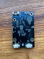
Pictures of the board attached.
I think the three pin connector for outputting the signal is on the bottom right.
Looks like there is two SMD resistors or capacitors in the signal path...???
All the best,
Salar

Attachments

  • image1.jpeg
    image1.jpeg
    616.9 KB · Views: 183
  • image4.jpeg
    image4.jpeg
    567.2 KB · Views: 185

First pair of speakers I'm (mostly) proud of :)

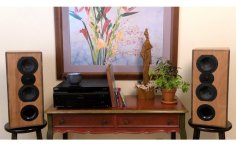
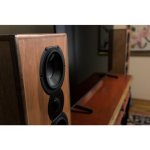
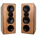
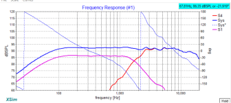
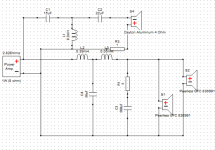
Here are some pictures, Xsim theoretical design pieces, and an outdoor measurement of the MTM pair I designed and built from scratch. Objectively there is room for improvement, but even so I think they sound great (because I made them? who knows ;P ). And I built more than one pair and tried to sell them (which is why I have this Etsy link... I'm not getting rid of them), and it is HARD to sell speakers you've made yourself. I should have known, but I had grand plans.... Ah, well.

Let me know what you think! I'm still learning and building (and have some ideas for the next projects....), and I want to take every lesson I can from this pair to improve the next 🙂

https://www.etsy.com/listing/1478244046/custom-designed-hand-made-hifi-speakers

Attachments

  • Speaker Back (Tilted).jpg
    Speaker Back (Tilted).jpg
    229 KB · Views: 252
  • Speaker_picture.jpg
    Speaker_picture.jpg
    134 KB · Views: 235
  • speaker_tv.jpg
    speaker_tv.jpg
    53.9 KB · Views: 304
  • speakerstilted.jpg
    speakerstilted.jpg
    152.5 KB · Views: 306
  • Impedance_XSIM.png
    Impedance_XSIM.png
    25 KB · Views: 319
  • FRD_XSIM.png
    FRD_XSIM.png
    30.7 KB · Views: 265
  • CrossoverCircuit.png
    CrossoverCircuit.png
    27.8 KB · Views: 273
  • OutsideFRD_0Deg.jpg
    OutsideFRD_0Deg.jpg
    103.2 KB · Views: 277
  • Like
Reactions: mr ed

Diaphragm / Cone size

I have always been wary of small woofer / subwoofer drivers with a large Xmax. Often the area of the surround is greater than that of the diaphragm. My question is: which specific part of the driver produces sound waves?

I am restricted in cabinet size and have a choice between 2 x 5" woofers or a single 6" - The diaphragm area for either scenario is the same.

Transistor Output Capacitance and signal integrity.

"The best amplifier is a wire with gain.. everything else is deductive".

Lets start with I am not an engineer, so there might be things that elude me, but are apparent to someone who is designing amplifiers and boy am I in the right place 🙂. The talent this site contains are enormous amount of talent,

The triode is for most part the best amplification device we have and very few sand devices come close. The only transistor that I know of is the JFet and one of the reasons can be found the internal capacitance. We could argue that Pentodes like the KT88 also is a very good device.

My topic for the day is Output Capacitance and signal integrity - if all else is equal, if we have component A and its gate to anode/drain/emitter is 25pF compared to component B which is half at 12pF. Would it stand to reason that this difference should be more favourable for the 12pF if we want to maintain the highest signal integrity.

A 300B tube have roughly Cg-a of 7.2pF. A KT88 on the other hand is 2.5pF and we know that similarly designed amplifiers will sound a bit brighter or more detailed on the KT vs the B amp.

The questions is simple: In an audio amplifier, is a low gate capacitance always favourable ?

For Sale Lot of Diodes, Standard, Schottkys, bridges, Zeners

sold

Asking $40 $30 to include USA ground shipping.


Here is a group of left over diodes from projects and projects that never happened.

There are INxxxx diodes, Schottkys from low volt to 600v, some Hexfreds, 15 FEP30DP 200v 30 amp arrays, low voltage 1-3 watt diodes and some 500mW to 1 watt zeners. Again most are small quantities of left overs, but some are in 10s, etc.

IMG_2478.JPG

For Sale miniDSP Flex

[EDIT]: SOLD. No longer available.

Latest (3rd generation) version of the popular miniDSP digital crossover and signal processing unit, "TRS" version with balanced analogue input and outputs, plus mini-TosLink, SPIDIF RCA and Bluetooth LDAC/APTX/AAC digital inputs (in addition to USB, of course).

All specs available at the manufacturer's site: https://www.minidsp.com/products/minidsp-in-a-box/flex

MINT IN BOX condition. Only used once for a system set-up.

250 GBP asking price. Payment by PayPal, or cash on collection.


Located in London (UK).
Shipping Worldwide via Parcelforce approx. 30 GBP.


282A0060.jpg

Flex Balanced9.jpg

Transmission Line

I saw this on FB.

"Work in progress …. Alpair 10.3 gold transmission line fully inspired from Jordan TLA design

First driver in full range mode

Second driver ( bottom ) filtered around 250 Hz with second order crossover

Plenty of dynamics , full bass response ( not yet measured )

My current speakers : magnepan MG12qr with custom made feets and external crossover"

Is it possible to do this with all drivers? Maybe Alpair 11MS?

Attachments

  • FB_IMG_1689593612041.jpg
    FB_IMG_1689593612041.jpg
    65.6 KB · Views: 183
  • FB_IMG_1689593619284.jpg
    FB_IMG_1689593619284.jpg
    67.7 KB · Views: 178
  • Like
Reactions: superlian

How to choose a sub driver?

Many years ago with the help of people in this forum I built a sub with a driver I had, a 10" which was pretty good.

That sub has been dismantled years ago. And I'd like to build a new one, to go low.

The room I'm running it in is only 3x6 meters so it doesn't need to be ridiculously loud. But I'm trying to find a good driver. The problem is that there are so many of them out there in the market, and I have no idea where to start

How can one tell if a driver is a good candidate? What specs should i look? Is it possible to look at the T/S parameters to quickly discard bad candidates?

Another FR attemp

Hi there! been a while
A frind carpenter luthier have some little home based studio and he got some speakers somewhere. They are Polkaudio rt55i. he wanted to make a box and he can litterally make any box. Control room is little, like 6x9, but still the box could potentially be big and inside an insulating, non mechanically connected with studio, dry wall.
I took the meassurements, vas method didnt worked out well so had to make the mass one...
Any suggestions welcomed, this are supossed to go in ceiling. Was thinking about a TQWT with new front bafle.
And a question, where would one choose roll off to begin considering TL dB/oct decrease and a little room? like 40hZ?
I was having fun a and then started doing something probably stupid, trying to compensate TL peaks with Difraction peaks. Not sure seems risky... could be adjusted at least in seem, anyway still room response not known
1653884079537.png

24“ Fane Colossus sub

Hey there,

I have this huge 24inch speaker from fane laying around since quite a while and I always wanted to build an enclousure for it.
My main problem is that almost every design I could think of is using way more space than I am willing to sacrifice.
I‘m thinking that with a sinple closed box I‘m just not using the whole potential this driver is giving but in order to get a well playing ported box I need more than 1000l to really play below 30hz.

I would be super happy if anybody has a Idea on what enclosure is fitting this speaker the best.

My goal is to have a box with a volume around 500l total to use for watching movies and listen to some music.
I want the sub to play from mid 20hz up to at least 80hz.

The TS prameters are:
fs: 21hz
Re: 6Ohm
Qes: 0.54
Qms: 4.1
Qts: 0.48
Vas: 980l
Vd: 3.8l
Cms: 1.7MNx10^-4
BL: 17.1Tesla
Mms: 316g
Rms: 11Ohm

Thank you guys!

Attachments

Advice on choosing a coaxial driver

As the title says, I'm on the search for information about coaxial drivers. I'd like to get a better understanding of the characteristics of the different types. And is there a design that is better than another?

My current speakers use a coax driver with a separate HF wave guide for the coax dome tweeter. Then I see there are also coax speakers use the woofer cone as the wave guide for a dome tweeter. And there are coax drivers that use a compression driver.

I am playing with the idea of adding a coax driver to the project I'm working on (home stereo, sound quality prioritized over spl). If I choose a coax driver, I would be looking for a 6" to 8". The coax driver would be for mids/ highs, and it will be crossed to a 12" woofer at around 300hz.

Is there a particular advantage to a coax driver using a compression driver for HF? I don't have any experience with horn speakers in hifi speakers, so I don't know what to expect. I've heard people discussing that the HF wave guide in front of the mid driver causes distortion, depending on the size of the wave guide. And people talk about how cone excursion is a problem when using the woofer as the HF wave guide.

I'd like to hear what you guys have to say on the subject.
  • Like
Reactions: Inductor and DblAA

Critique my Design - 8th Order Bandpass

The objective here is a pro-sound sub useable from 40hz upwards, with a net volume somewhere around 10 cubic feet.

The driver is a Planet Audio FU18, which is a clone of the old Cerwin Vega Stroker subs. It's a dual two ohm voice coil, so the power plot is really 2 watts, but I think the efficiency is pretty good anyway.


I anyone has the inclination to have a look at the Hornresp file, it would be very much appreciated.

Screenshot 2023-07-17 090737.png


Screenshot 2023-07-17 091035.png


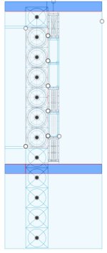
Layout will be pretty well like this picture, but the upper chamber will have 4 ports passing through to the lower chamber to symmetrically load the woofer. It's an old speaker and I don't know that it has the strongest cone int he world. Two ports will simply be holes cut in The 17mm plywood used for the build for ease of construction.


Screenshot 2023-07-17 091938.png
Screenshot 2023-07-17 092227.png

Attachments

Help with SDX10

I have 2 CSS SDX10 subs that have open voice coils but are otherwise in great condition. The woofers move freely and the cones and surrounds are in in excellent condition. CSS said they can't repair. I'm looking for any suggestions for how I might repair or there is a repair shop that might have a voice coil that would fit before I throw them out.
IMG_9127.jpg

TIA,
Jim
IMG_9128.jpg

Quick first look at Burson Audio V6 Classic opamp

I was furnished a pair of Burson Audio V6 Classic opamps to evaluate. The deal is that in exchange for the evaluation pair of opamps I try them out and post my impressions here. So here we go...
  1. They work. No issues in my simple opamp-based 2-stage phono preamp (input opamp > passive RIAA EQ > DC coupled to output opamp). Voltages check out, it plays sound.
  2. The only objective feature I can give you right away is DC offset.
    • The previously used opamps are LM4562. With those in the preamp, the DC offset at the outputs is 2.1mV in one channel, 1.3mV in the other channel.
    • With the Burson V6 Classic opamps, the DC offset is very slightly higher: 2.1mV in once channel, 2.8mV in the other channel. Since the V6 Classic has a JFET pair input, I'd expect its DC offset to be higher than that. It did take a half-hour or so for the DC offset to come down from about 10mV shortly after power-on.
    • The DC offset was much higher with a pair of OPA2134, but unfortunately I can't put those back in now because they're now installed in a different preamp. I did try OPA2134 in this circuit first, but saw almost half a volt DC offset, decided to try LM4562, and wound up settling on those.
    • So... The V6 Classic opamps have notably lower DC offset in this circuit than OPA2134, and only slightly higher DC offset than LM4562.
  3. As far as my subjective impression goes, the V6 Classic opamps sound good to me in this particular circuit, for whatever that's worth. Maybe the V6 Classic sounds a bit 'warmer' or 'rounder' than with the LM4562 in circuit, but I suppose that's not surprising since many have described the perceived sound of LM4562 as more 'detailed', 'analytical', 'clinical', etc. than other opamps like OPA2134, etc. Any differences are subtle, as you would imagine. I figure THD levels from any reasonable opamp are going to be so low as to be inaudible, so one should expect any differences to be small, unless something was seriously wrong.
  4. Physically, the package is super-easy to install and remove from standard DIP8 sockets. It's very friendly for those who wish to 'roll' opamps. You're far less likely to bend pins inserting or removing these Burson V6 opamp packages than with a standard dual inline 8-pin opamp IC.
For those who care, the system used consists of a rebuilt Thorens TD124 turntable with Audio Technica ATP-12T tonearm and Audio Technica AT-VM95ML cartridge, into the preamp described above, into a passive selector switch and stepped attenuator, and finally to a pair of JBL LSR 305P active speakers. The listening room is small, about 4 meters wide by 8 meters long by 2.5 meters floor to ceiling.

I hope that helps someone. I'll report back if I have anything noteworthy to add.

ADC input range confusion

I'm trying to use the line level inputs of the WM8731 and the "Absolute Maximum Ratings" below was confusing to me:
1689361637255.png

As can be seen, the datasheet says the absolute minimum for analog inputs are AGND(0) - 0.3V = -0.3V whereas a line level input could swing to -1V. I also see a lot of projects just using the line inputs on this chip disregarding -0.3V. I see on the datasheet and it definitely works. So the logical conclusion is that I'm missing some obvious knowledge. Could anybody explain?

Best

Investigating Balanced Tube Preamp

Hello all,
am new to the idea of using a preamp, always thought I could get away with a volume control on the source and directly go into the power amp. However, lately I dabbled using the preamp section of a Yamaha AV1 receiver between source and power amp (ARC VS115) and it has a bit more "foundation" with it. SO now I am infected with the idea of getting a balanced tube preamp and really intrigued by this chinese clone
Hi End AudioResearch ARC Tube Preamplifier Balanced/RCA IN&OUT,12AU7/ECC83+ECC88/6DJ8 Preamp DIY Kit|Amplifier| - AliExpress
There are many questions just arising from the text (it can be found on ebay as well, but the pictures on this ad are better)

Assumptions:
1) the coupling transformers are to connect unbalanced inputs and process them as balanced
2) the rectification and voltage regulation is included (board and part-wise, except the EZ90 tube)
3) hard time finding a transformer fitting the requirement 280V (two sides), this one is quite close 80W pure copper R-core transformer for tube preamp / phono 280V-0-280V +6.3V *2 | eBay
would one get away in connecting the 2nd 6.3V circuit in series to the first one to tap of 2A @ 6.3V and for the series connection 12.6V at (2A, instead of 3A)?
4)not familiar with preamp topology...no need for an output transformer???
5) a quick search would have the total cost for board, transformer, tubes at 335 US, worth it or better get something what looks like the finished (copy)?
12AU7 ECC88 Valve Tube Bile Preamp Pre amp American ARC Circuit Tube HiFi Balanced Bile Preamp Chassis shell/finished machine|Amplifier| - AliExpress
for roughly twice the price
6) I am really interested in building a kit this time (it has been a long time since I did something in the amplification world)

What are your thoughts? Have you build one of these clones yourself?

Cheers
brxl

Adcom GFP-750 Upgrade Right Channel Issues

I'm working on an upgrade modification for this GFP-750 preamp. Once the cap portion of the upgrade was installed, I noticed I had no right channel when the unit was out of passive mode. I've checked components, traces, solder joints, and voltages. Some of the voltages are off on the right channel, but I can't figure out what is causing them to be off. Any help would be appreciated.
Screenshot_20230714_085202_Word.jpg
20230715_143610.jpg

Dynaudio Esotec 15W-75-4 woofers and D-28 tweeters

Dynaudio Esotec 15W-75-4 Ohm woofers and D-28 tweeters

As on photos, speakers are 100% flawless working in IMHO in great shape. ( Other than back-foam on woofers has disintegrated and was removed..like on all of them). Both woofers measure 3,3 Ohms ..and tweeters 5,4 Ohms/DC resistance.

Asking for 260€ plus shipping for all 4 speakers.

Regards, Davorin
DSC_1814.JPG
DSC_1816.JPG
DSC_1817.JPG
DSC_1818.JPG
DSC_1821.JPG
DSC_1823.JPG

Attachments

  • DSC_1822.JPG
    DSC_1822.JPG
    240.6 KB · Views: 158

  • Locked
Bliesma T34B issues

I just received my T34B tweeters today and got all excited to open them up and admire the fine European craftsmanship, but what i found instead was a back chamber of a driver had come off in transit. The other one still was intact but I only needed to pry very lightly and it came off as well.

The problem is they glued the chamber onto the polished and plated surface of the magnet asy. The magnet surface isn't rough enough to adhere to the adhesive they used so it can get a good bite on it. Needless to say I'm not impressed. At least you guys can see what these things look like inside. There is a 35mm disc of wool felt for dampening inside the chamber. Nothing fancy. I swept both drivers without chambers and they both sound fine, so I'll glue to chambers back on again.

Very disappointing. I thought the Germans know what they're doing with this stuff.

Attachments

  • 20230705_215054.jpg
    20230705_215054.jpg
    408.4 KB · Views: 429
  • Like
Reactions: IamJF

Placing the 2uH power inductor WWW.BUILDAUDIOAMPS.COM project 3

http://buildaudioamps.com/project-3/

Hey forum people,

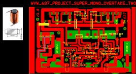
Does anybody know weither the line, marked by a blue line, is correctly placed? Should i put a GND wire under it?

Question 2: Is the power inductor as in photo left upper corner, the right choice ? Is there a difference between axle and no-axle?

Greets, Wouter van Wegen, PascalByThree

Attachments

  • WVW_SNAP_PRJ3_GND_LINE_Q.png
    WVW_SNAP_PRJ3_GND_LINE_Q.png
    64.1 KB · Views: 120

From symmetrical to asymmetrical using the Fibonacci series

From symmetrical to asymmetrical using the Fibonacci series.

In self-construction it is advantageous to use asymmetrical parts instead of symmetrical ones. When choosing measures I have a habit of choosing values from the Fibonacci series to avoid having parts with multiple measures.

In my latest MDD3ZC350 V2 prototype I improved the detail of the reproduction by moving the base supports from a symmetrical to an asymmetrical configuration and repositioning the force application points. The use of asymmetrical parts can also be advantageous in other projects (frames, stands, racks, ...) by reducing the possibility of triggering spurious vibrations.

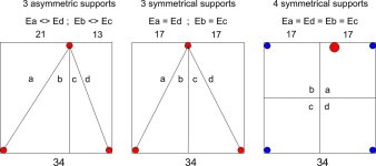
In the first version of the MDD3ZC350 prototype the supports were at the vertices of an isosceles triangle (central figure – 3 symmetrical supports). The position of the supports divides the 340 x 340 x 20 mm plywood base into four sections (a), (b), (c), (d) with mirrored shape and constraints in pairs. The vibrational energy that can be stored in section (a) is the same that can be stored in section (d). The vibrational energy that can be stored in section (b), is the same that can be stored in section (c). More or less damped vibrations can be triggered both between sections (a) and (d) and between sections (b) and (c). The subsonic mount bracket was fixed in the center of the underside of the triangle and facilitated the triggering of unwanted vibrations.

In the second version of the MDD3ZC350 V2 prototype the supports were at the vertices of a scalene triangle (figure on the left – 3 asymmetric supports). The position of the supports divides the 340 x 340 x 20 mm plywood base into four sections (a), (b), (c), (d) with different shape and constraints. The vibrational energy that can be stored in section (a) is different from that which can be stored in section (d). The vibrational energy that can be stored in section (b) is different from that which can be stored in section (c). Vibrations can NOT be triggered between sections (a) and (d) or between sections (b) and (c). The subsonic mount bracket is attached close to the top mount further reduces the likelihood of unwanted vibration being triggered.

In a base with 4 supports (figure on the right – 4 symmetrical supports) there are four sections (a), (b), (c), (d) with the same or specular shape and constraints. The vibrational energy that can be stored in section (a) is the same that can be stored in sections (b), (c) and (d). More or less damped vibrations can be triggered between all pairs of sections. If there are problems, the configuration can be transformed into an asymmetrical one with 3 supports by adding a fifth support slightly higher than the others in asymmetrical positions. The material to be used can change according to the system and the floor in which it is used, it can be rigid or yielding, elastic or inelastic.

The use of supports in asymmetrical positions can be useful in self-construction where design systems with simulations that directly control the vibrations of the parts are not used. If a symmetrical system is well designed, with no vibrations, switching to an asymmetrical setup will bring no benefit.

Thanks for the attention.

Attachments

  • FibonacciSupporti.jpg
    FibonacciSupporti.jpg
    52.4 KB · Views: 104
  • Like
Reactions: AllenB

Should ground wires be isolated on splitting / AB switching / summing?

So I've been DIYing and I'm wondering, is it ok to keep ground wires from different signals connected?

For example #1 I'm making a simple XLR A/B box, and I'm not sure if I need a three pole switch or if I can use two and keep ground wires from both inputs connected to the output.

#2 I have two TRS inputs and 2 TRS outputs, and I'm gonna use a switch to split sides or keep them stereo. If the switch is on, TRS output #1 will only out merged L sides from both inputs, and #2 merged R sides, and when the switch is off, both stereo signals should just pass through. It's the same situation, do I need a triple pole switch, with the 3rd pole being used to disconnect grounds while not splitting sides, or is it ok to keep them connected at all times?

What/who are Visaton speakers for, and is it me?

Just been daydreaming about speaker builds, and thought I liked the look of Visatons, because they're cheap and have have pretty neat Frequency Response charts. Until I go to calculate the enclosure and they come out freakishly huge. Like, 200 litres for an 8 inch woofer (W 200 8). The 6.5 inch version has a qts of 0.81, and a similarly sized cabinet. I was scratching my head for a bit, wondering if the datasheet was wrong, until someone mentioned 'open baffle'. So does that mean you can either stuff them in a smaller cabinet and ruin that beautiful flat frequency chart, OR just rely on your room to do that for you? The other thing that comes up is a lot of people seem to like them for replacing 'vintage' speakers. So i guess in a small enclosure they're kind of a bit lazy, warm, quiet - good for the oldies? They do have a bit of that aesthetic to them. They don't have that aggressive kind of garish 'Lamborghini" kind of design language that others go for.
That said they have these 4 inch FR speakers that look great for satellites or bluetooth speakers. I haven't quite looked at their 12 inches - but I'm thinking those would actually work quite nicely in a guitar amp?
Interested in anyone's experiences with them
https://www.soundlabsgroup.com.au/p/V-9063-W170/W+170+-+8+Ohm
https://www.digikey.com.au/en/products/detail/visaton-gmbh-co-kg/FRS-8-M-8-OHM/9842306

About Crossovers

Hello, I have a question that runs in my mind about crossover freq, we have the usual passive crossovers low pass/high pass 2.5khz , 3, 3.5 ,4 etc, and active with a knob from 250 to 100hz for low pass on car amps for example.
Let's say we need a high pass filter for our tweeters let's say at 3khz ( active or passive doesn't matter ) , now if we look at the musical notes frequencies , closest to 3khz we have :
F#7/Gb7​
2959.96​
G7​
3135.96​
if we look for 3.5khz we have:
A7​
3520.00​
3520hz which is closer to 3500, we use 3500 instead of 3520 for "easier manufacturing" component values ? or why.

Is there a difference if we cross over at 3khz or cross over on the " exact note freq " at 2959hz ?.

, Bruno.

FM in car radio won't find a channel, adding bluetooth and a mystery.

I have an 'old' radio in my truck (2001 ram) that won't find any stations, won't play stations manually tuned, and if saved in memory and retrieved will 'play' but be full of static. Its kinda unique, for whatever reason, as in i haven't seen a picture of another one on the internet so far (there is one craigslist post of the part number, but thats it). Plenty of other models of radios (i have 2 others) for the 'same truck' (anything from like 1970-2002, trucks, vans, durangos whatever), just not this particular one. I've been hoping to fix it, instead of just replace it, both because of the 1.5 din size and uniqueness and then stick a bluetooth module in the thing probably on the CD lines to modernize it just a tiny bit. Are there some tests i could do to narrow down the FM issues? I assume its not the truck, as i have 2 other radios I've stuck in the thing and both work just fine with the same hookup, one being as old and one being a tiny bit newer (and its taken a swim).

This is the face of the radio in question. Part number P82301040.

IMG_4056.jpg


I replaced it with this one (from a donor truck) when the tuner originally died (its been a while). One day the volume knob died and this whole project got kicked in motion. Turns out a rotary encoder in it had the backing/detent disc shatter. Simple fix, right? Get another Alps EC11 encoder with a threaded body, 4mm slotted shaft 30mm long with button. Apparently this is not a thing that exists (anymore? or because the manufacturer bought so many they have a custom part?). So instead i got the cheapest 15 position 30 detent EC11 i could find and hoped for the best. Opened it up and took the disc, stuck it in the old body and it works fine. Sadly, this one was flooded at least once in my yard and the CD player doesn't work, even though it takes and ejects CDs, the CD motor spins when forced and the laser motor seeks if moved out of place. In practice it never spins up (wired in leads to spindle motor and checked) just throws an ERR and splits out the CD when you try to play. Since i had planned on intercepting the CD lines for the bluetooth thing this is also technically broken for me. And its ugly, though it was uglier. It had amber LEDs on the balance knobs. Those were just slotted in, so i removed those and its slightly less ugly now. But its also not unique... this seems to be one of the most normal radios for my truck (I think the version that looks like this but also has a cassette is the most normal one). So instead I still hope to fix my original radio.

Donor radio face, part number P04704373AE.

IMG_4057.jpg


I kept looking all over for even a bad picture in a scrapyard of my radio on the hopes of just mixing parts to make one working one, still haven't seen another example in the wild. Its the internet, how can there be no other examples of this anywhere? Widening my search i came up with a few more radios with faces more like my original. Fairly common to see a cassette only version like this: Cassette only on Ebay. Then some more strange ones that don't appear on lists of radio options for my truck: No cassette only on Ebay. No CD only on Ebay. Weird stuff. But this last one, no CD but otherwise very similar face to mine also has an identical(?) plug layout, and i saw a cheap and clean one up for bid and got it on hopes of the board being a de-populated version of mine. No such luck there. Here is the clean face of my 'new' radio. Looks like its almost never been touched...

'New' radio, part number P04704360.

IMG_4071.jpg


And now for the guts. The boards are very obviously quite different, but it does look like the tuner section is fairly similar. Maybe i can compare them to help find faults in mine? The new one does work in my truck, while the old still doesn't, Also note the date code, i assume, on the big chip at the bottom 95 48. Which is a bunch older than my 2001 truck. A big bunch. As far as i know its the original radio though. Original radio board with CD.

IMG_4069.jpg


'New' radio without CD. Date code on its big, but different, chip is 94 52, so a fairly similar vintage. Also so darn clean. No idea what this is out of to be this clean.

IMG_4067.jpg


But the cans are probably the same. So yay? Maybe? Or do the supporting tuned thingies need tweaking to make it work so its basically hopeless? Original can.

IMG_4070.jpg


'New' can.

IMG_4068.jpg


I have temporarily run out of knowledge though. I can do electronics to some extent, but i know nothing about voodoo, err radio. I do think that can has something to do with it. No idea if that is whats broken. So far testing voltages on the two boards seems close enough on all the pins of the cans that i would say it should work, if it works, or i'm not supposed to get voltage but something fancier and i don't have the tools to measure it.

I did have another thought here as i got the very clean 'new' radio. I don't actually care about the CD player. Only wanted it for the bluetooth module to splice into and play silent CDs with phone music instead. This is how i had read others having done it, either with cassette or CD. Seemed like a fun project to 'modernize' without actually going for a ugly modern 'solution'. But, would it be simple to splice into the AM source instead, before the mux which i assume is somewhere (haven't really gone down this path yet) either breaking the traces from the AM source completely or putting in some switch that does it. Then i could have the 'new' radio play FM normally and hit the AM/FM button would swap to bluetooth. I assume the board doesn't care what the source is doing on the AM side unlike the cassette/CD side, where if it doesn't play it won't stay on that input.

Fun little project so far even though i haven't done much.

Driven Cascode Novelty Circuit

Following my experiments with the modular power amp https://www.diyaudio.com/community/threads/rcp130-modular-lateral-mosfet-power-amplifier.368795/ where I gathered knowledge regarding several types of input stages I finally chose the mirror loaded complementary symmetrical IPS described here: https://www.diyaudio.com/community/threads/slone-amp-final-solution.379346/

When using a symmetrical complementary IPS loaded with mirrors we face ourselves with the typical problem: “the VAS input voltage is not defined by any reference voltage, so it depends on the VAS base current and the Early voltage of each transistor connected to that node, as well as the common mode offset current of the LTP.”

To circumvent this problem, I added a 1k resistor (R12) between the emitters of the top CM (Q10) and VAS bjt (Q3). Fig 1
1661003027220.png

Fig 1 (R12 action)

According to Keantoken, R12 works actively by converting the VAS and CM into a CCS (analogous to the standard 2Q CCS).

As I see it, the current in the CM is perfectly defined and produces a voltage drop across R2 (Q10 emitter degeneration 133ohm).

R12 transfers this voltage to the emitter of the VAS Q3 so a fixed current runs through its degeneration resistor R11.

NOTE: R12 can not be replicated in the lower VAS (Q5) because that way both positive and negative VAS would try to fix a current in the bias spreader and due to differences in NPN PNP transistors, the current would never be exactly equal… (Both VAS currents would fight each other).

As is, R12 fixes the current on the positive VAS and the negative VAS just follows as if loaded by a CCS.


Another benefit from this configuration is that OLG is not severely decreased as in the case where both VAS currents are regulated.

Lowering R12 value increases VAS current stability but lowers OLG. The 1kohm was chosen because it represents a good compromise between current steadiness and High OLG.

1661003054617.png

Fig 2 (New circuit OLG plot)

-------------------------------------- NOVELTY DRIVEN CASCODE ------------------------------------

I chose to cascode the input jfets because when the cascode is “Driven with output signal” it does minimize voltage fluctuations between the sources and drains of these JFETS.

This “constant voltage” approach can effectively reduce higher order harmonic distortions.

In my prototype, the voltage divider that sets the cascode base voltage Fig 3 (R37 R45) is modulated by input signal through the connection CCSP…. While this method works, there is always a small current diverted from the Jfet sources to the voltage divider and Input Jfets Vds is not really constant.

1661003094391.png

Fig 3 (Prototype driven cascode circuit)

In my new design Fig 4 I chose to drive the cascode bases through a NFB replica coming from the output signal.

In this case the negative feedback replica circuit (R59 R60) modulates both positive (Q7 Q8) and negative (Q12 Q13) cascodes, through the bases of the followers (Q19 Q20).

This way, by carefully choosing R60 value (1k98 ohm) I can stabilize the voltage between the Drains and Sources of the IPS JFETs.


1661003168833.png

Fig 4 (New Cascode drive circuit)

Looking at Fig 5 I placed two test points: JD on the Drain and JS on the source of input jfet J1.

When running the simulation, we see that JD sits at 9.572V and JS at 98.6mV

Plotting V(jd)-9.572 and V(js)-98.6mV we see clearly that both curves are coincident and by tuning R60 we can actually null the difference.

Here we see 542uV Vds voltage variation @ 1KHz 290W.

1661003225191.png

Fig 5 (Input Jfet Vds plot)

Viewing the results of the .four command Fig 6 (1Khz 290W), we observe that THD is minimized when both curves are coincident.

1661003283971.png

Fig 6 (1KHz 390W FFT)

I hope this new method gathers enough interest to produce a fruitful discussion on how to best “drive” both cascodes simultaneously.
To facilitate analysis I am including and .ASC file that can be used for testing.

All models are included in the .ASC file so it runs directly in LTSPICE.

This simulation is initially set to produce 300W into a load of 5ohm @ 20KHz

You can choose other values by modifying the values of:

.param power=300

.param freq 20k

.param rload=5

Control transient is:

.tran 0 {{delay}+(20/freq)} {delay} {timestep}

DISCLAIMER:
The present schematic must not be used for commercial purposes.
This is can only to be used as a DIY project.

Attachments

  • Like
Reactions: astx

Primare A20 Amplifier Hum

Hi, I have an old Primare A20 that’s been working fine for many years. Recently it’s started to hum through the speakers. The noise sounds like ground hum and is there even with no inputs connected and doesn’t vary with the volume. The sound is the same through both channels. I’ve checked and all the ground connections are fine. Is there a particular component that could cause this issue?

2.5 way Line Array. Will a common enclosure emulate a falling Q with rising frequency?

I'm working on a line array design that will go behind an acoustically transparent projector screen. The original idea was to use six 6.5" drivers and six Neo8 planars. But modeling in WinISD, and test speakers showed more low-end drop off than I was hoping for. So now I am considering changing the design over to a 2.5-way design; running the six speakers directly behind the screen upto 550 Hz, and the speakers that would be behind or below the projector screen only upto 80 Hz; hoping that the omni nature of the lower frequencies will not give me horrible diffraction artifacts off the projector screen frame and any other gear that happens to be in front of the speaker.

I am leaning towards having all 12 of the 6.5" drivers share a common rear chamber tuned to Q=0.707. My thinking is that as the frequencies rise above 80 Hz that the effective Q of the enclosure will shrink (because the low frequency drivers will be 15 dB down above 200 Hz) - improving impulse response. Is this a bad idea? Do 2.5 way speakers need to have the low frequency driver(s) in their own enclosure for some reason?

For six of the 6.5" drivers:
Q 0.707 = 6627 in^3
Q 0.577 = 16,100 in ^3 Almost 3x the volume required!


CENTER 2.5 frame highlight.JPGCENTER 2.5 xSIM.JPGLine Array Fusion360.JPG

Beginning my DIY build, (2x) 2xNC500MP

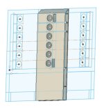
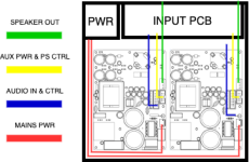
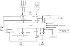
First DIY amp build. Got four NC500MP modules, planning two put into a box: https://uk.farnell.com/metcase/m550...250mm/dp/1510826?CMP=e-email-sys-orderack-GLB (for a total of two boxes). Also planning to design a pcb (block diagram attached) to perform auto signal sense, and mute on startup, 12V IO. What do you think? Any tips of advice? Thanks.

Attachments

  • 2xnc500mp_block_diagram.png
    2xnc500mp_block_diagram.png
    946.4 KB · Views: 96
  • nc500mp_block_diagram-2xnc500mp.png
    nc500mp_block_diagram-2xnc500mp.png
    41.9 KB · Views: 96
Projects by fanatics, for fanatics
Get answers and advice for everyone wanting to learn the art of audio.
Join the Community
507,913
Members
7,893,431
Messages

Filter

Forum Statistics

Threads
406,476
Messages
7,893,431
Members
507,913
Latest member
rajkps4