Dear Friends,
I am often using an Xive 48V Phantom Power Supply as an alternative to my
SQN - 3 field mixer. Much less to carry around!
The Xvive just provides 48V Phantom Power -no pots to turn - and passes the mics signal to the recording device.
The Xvive should do this unaltered but it doesn`t - below 200hz it starts to cut.
I do not find the graph right now, but as far as I remember, at 50hz everything is gone.
I tested two Xvive against the SQN-3 (that also provides phantom power)
the SQN`s signal is flat, no low-cut, whereas the two Xvive act exactly the same,
as low cut / high pass.
So probably a design flaw.
Unfortunately, the company did not respond.
Can anyone give me an idea what could be the reason?
There is no transformer incorporated in the design, so this can be ruled out.
Maybe some DC-decoupling that might work as a high-pass / low cut?
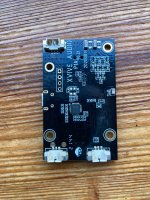
Pictures of the board attached.
I think the three pin connector for outputting the signal is on the bottom right.
Looks like there is two SMD resistors or capacitors in the signal path...???
All the best,
Salar
I am often using an Xive 48V Phantom Power Supply as an alternative to my
SQN - 3 field mixer. Much less to carry around!
The Xvive just provides 48V Phantom Power -no pots to turn - and passes the mics signal to the recording device.
The Xvive should do this unaltered but it doesn`t - below 200hz it starts to cut.
I do not find the graph right now, but as far as I remember, at 50hz everything is gone.
I tested two Xvive against the SQN-3 (that also provides phantom power)
the SQN`s signal is flat, no low-cut, whereas the two Xvive act exactly the same,
as low cut / high pass.
So probably a design flaw.
Unfortunately, the company did not respond.
Can anyone give me an idea what could be the reason?
There is no transformer incorporated in the design, so this can be ruled out.
Maybe some DC-decoupling that might work as a high-pass / low cut?
Pictures of the board attached.
I think the three pin connector for outputting the signal is on the bottom right.
Looks like there is two SMD resistors or capacitors in the signal path...???
All the best,
Salar
Attachments

Last edited:
Is there a setting to make it compensate for proximity effect somewhere? A 200 Hz high-pass would make sense if you wanted to compensate for proximity effect.
No, there is nothing. The Xvive is originally meant to just provide Phantom Power
for mixers, field or studio, that have mic-sensitive inputs but no phantom power built in.
So bass-cut is left to the mixer. It also must work with a variety of microphones.
for mixers, field or studio, that have mic-sensitive inputs but no phantom power built in.
So bass-cut is left to the mixer. It also must work with a variety of microphones.
It is bound to have AC coupling to keep the 48 V out of the mixer, it is just odd that the corner frequency is so high - although they don't seem to specify anywhere what the corner frequency is supposed to be.
How did you measure it? Was the load impedance of the order of 2 kohm or more?
How did you measure it? Was the load impedance of the order of 2 kohm or more?
No, I simply recorded a sweep from 20hz to 20kHz, without a microphone in the signal path, once through the SQN, once through the Xvive.
The SQN also has 48V phantom power. But with the SQN the frequency response is flat.
Unfortunately, I deleted the screenshot where you could compare both waveforms.
The SQN also has 48V phantom power. But with the SQN the frequency response is flat.
Unfortunately, I deleted the screenshot where you could compare both waveforms.
So the load of the Xvive's output was simply the microphone input of your recording device. That should work normally.
You could try to reverse-engineer where the AC blocking capacitors are located, shunt them with 22 uF, 63 V electrolytic capacitors and hope that whatever protection circuitry is used to protect the load during phantom supply switch-on and switch-off also works with the increased capacitance. It's silly that that is needed, though.
You could try to reverse-engineer where the AC blocking capacitors are located, shunt them with 22 uF, 63 V electrolytic capacitors and hope that whatever protection circuitry is used to protect the load during phantom supply switch-on and switch-off also works with the increased capacitance. It's silly that that is needed, though.
The SQN presumably supplied a line level signal rather than a microphone level signal to your recorder. Does that affect the recorder's frequency response? For example, did the recorder's microphone input have a high-pass turned on by mistake?
Thanks for thinking at that but no. I called it SQN for convinience, but the long defunct German company that built the mixer was called SIE. The field mixers from SIE were built on behalf of German Public Broadcast in the late seventies to implement features the SQN - 3 did not have at that time:
Switcheable sensitivity and Phantom voltages without the need of using a flat screwdriver, LED instead of VU - and the ability to switch between studio level and mic level outputs!
Back to Xvive: Could it be that the two little SMD fellas above the lower right connector are the original decoupling capacitors? Assuming they must be 63V, what do you think is the highest capacitance they could fit into the size? Still uF or already nF? Wouldn’t be the cutoff frequency even much more higher?
If you have a multimeter, you can measure if they are capacitors or something else, like SMD ferrite beads.
Indeed, so then the DC blocking capacitors have to be somewhere else.
When you power everything down and do a resistance measurement of these components, just mounted on the board, and measure a very large resistance, you know they are capacitors.
If you measure a resistance of a few ohm or less, they are probably ferrite beads to suppress RF interference.
If you don't measure a very large resistance, but do measure more than 20 kohm, they are probably capacitors and the other circuitry on the board probably causes the reading.
Something else came into my mind, this has nothing to do with the fact, that the Xvive cuts low freqencies, as I did measure before this mod:I put in a 1:1 transformer to play things safe when converting the signal from balanced to single ended. So the transformer should work as a DC - blocker. But it is directly soldered to the output. Need to check the signal path.
Well... I modded the Xvive now.
I replaced the original ceramic capacitors that block the audio path against phantom power with
Wima Foil capacitors. I assume the original ceramics were between 0,47µF and 1µF.
So it is now 5,4µF, this is the most I could squeeze in the tight space with foils.
But using a Neutrik NTE-1 transformer at the output for going from balanced to unbalanced
must have introduced a new problem: Impedance of the NTE-1 seems to be 200ohms.
So corner frequency is around 150hz, looks like drop begins from 125hz.
Questions:
-A 1:1 transformer like the NTE-1 does not "see" the input impedance of the destination,
the mic preamp in my camera, that has about 2Kohms?
-Does anyone know whether the NTE-1 can block Phantom Power?
So that I can simlpy omit the capacitors?
Al the best,
Salar
For THIS transformer, or for ANY transformer?
Aren't isolation transformers a common solution for blocking
phantom power?
Aren't isolation transformers a common solution for blocking
phantom power?
If you apply DC to a transformer you will saturate the core and will generate distorsions.
So no, the transformer must not see DC.
So no, the transformer must not see DC.
Got it, many thanks!
Now as I'll very likely need to rip out the foils and have to put in electrolytics
as DC-blockers to match the low impedance of the transformer, what about leakage current?
Will still a resistor to ground be needed or will the transformer drain it?
The audio signal path of the XVIVE is passive and simple: Connection to mic > capacitor for blocking 48V > Resistor 100ohm (in signal path, not between signal and to GND) > 1:1 transformer (added by me for going unbalanced) > Output
Last edited:
If you apply DC to a transformer you will saturate the core and will generate distorsions.
So no, the transformer must not see DC.
You don't saturate anything with 48 V DC between primary and secondary.
Thanks!
Another problem, I am stumbling over very basic things here:
The audio transformer, Neutrik NTE1, 1:1 ratio) has 200ohm impedance.
I am using a Sennheiser MKH-416, that "wants" at least 400 ohm impedance,
newer models "want" 800ohm impedance.
I just do not find any info if I can artificially "raise" impedance by putting resistors
in series (not connected to GND) in the signal path...?
And, basic question: When the secondary winding of the 1:1 audio transformer (also 200ohm)
going to the mic preamp is terminated by higher impedance (in my case 2200ohm),
the primary winding, where the mic is attached to will still have an impedance of 200ohm, correct?
Last edited:
Well... I modded the Xvive now.
I replaced the original ceramic capacitors that block the audio path against phantom power with
Wima Foil capacitors. I assume the original ceramics were between 0,47µF and 1µF.
So it is now 5,4µF, this is the most I could squeeze in the tight space with foils.
But using a Neutrik NTE-1 transformer at the output for going from balanced to unbalanced
must have introduced a new problem: Impedance of the NTE-1 seems to be 200ohms.
So corner frequency is around 150hz, looks like drop begins from 125hz.
Just to get this clear: so you established that those things were SMD capacitors with some unknown value, that they were connected as AC coupling capacitors (one side to the input XLR connector, other side to the output XLR connector), replaced them with 5.4 uF film capacitors and the cut-off frequency dropped from 200 Hz to 150 Hz? Or is there any risk that you replaced the wrong components and that your measurement is not accurate enough to see whether the corner frequency has changed?
Questions:
-A 1:1 transformer like the NTE-1 does not "see" the input impedance of the destination,
the mic preamp in my camera, that has about 2Kohms?
It does see the load impedance. Ideally, the primary impedance is the load impedance that is connected to the secondary side divided by the square of the turns ratio. You get deviations from that due to wire resistance and extra deviations at very low and very high frequencies. At very low frequencies, the impedance drops due to the finite magnetizing inductance.
Neutrik provides practically no information about the NTE-1, see
https://www.neutrik.com/en/product/nte1 , except that it is a 1:1 transformer. At 2 kohm load, its input impedance will be close to 2 kohm at midband frequencies, but due to the inadequate information, I haven't a clue below what frequency it starts dropping.
-Does anyone know whether the NTE-1 can block Phantom Power?
So that I can simlpy omit the capacitors?
Al the best,
Salar
It can, but are you sure the SMD things are indeed capacitors that were connected with one side to the input XLR connector and the other side to the output XLR connector?
- Home
- Live Sound
- Instruments and Amps
- Xvive 48V Phantom Power supply acts a high pass