From symmetrical to asymmetrical using the Fibonacci series.
In self-construction it is advantageous to use asymmetrical parts instead of symmetrical ones. When choosing measures I have a habit of choosing values from the Fibonacci series to avoid having parts with multiple measures.
In my latest MDD3ZC350 V2 prototype I improved the detail of the reproduction by moving the base supports from a symmetrical to an asymmetrical configuration and repositioning the force application points. The use of asymmetrical parts can also be advantageous in other projects (frames, stands, racks, ...) by reducing the possibility of triggering spurious vibrations.
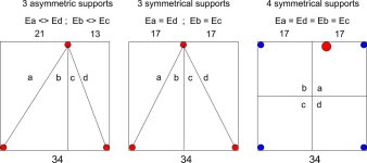
In the first version of the MDD3ZC350 prototype the supports were at the vertices of an isosceles triangle (central figure – 3 symmetrical supports). The position of the supports divides the 340 x 340 x 20 mm plywood base into four sections (a), (b), (c), (d) with mirrored shape and constraints in pairs. The vibrational energy that can be stored in section (a) is the same that can be stored in section (d). The vibrational energy that can be stored in section (b), is the same that can be stored in section (c). More or less damped vibrations can be triggered both between sections (a) and (d) and between sections (b) and (c). The subsonic mount bracket was fixed in the center of the underside of the triangle and facilitated the triggering of unwanted vibrations.
In the second version of the MDD3ZC350 V2 prototype the supports were at the vertices of a scalene triangle (figure on the left – 3 asymmetric supports). The position of the supports divides the 340 x 340 x 20 mm plywood base into four sections (a), (b), (c), (d) with different shape and constraints. The vibrational energy that can be stored in section (a) is different from that which can be stored in section (d). The vibrational energy that can be stored in section (b) is different from that which can be stored in section (c). Vibrations can NOT be triggered between sections (a) and (d) or between sections (b) and (c). The subsonic mount bracket is attached close to the top mount further reduces the likelihood of unwanted vibration being triggered.
In a base with 4 supports (figure on the right – 4 symmetrical supports) there are four sections (a), (b), (c), (d) with the same or specular shape and constraints. The vibrational energy that can be stored in section (a) is the same that can be stored in sections (b), (c) and (d). More or less damped vibrations can be triggered between all pairs of sections. If there are problems, the configuration can be transformed into an asymmetrical one with 3 supports by adding a fifth support slightly higher than the others in asymmetrical positions. The material to be used can change according to the system and the floor in which it is used, it can be rigid or yielding, elastic or inelastic.
The use of supports in asymmetrical positions can be useful in self-construction where design systems with simulations that directly control the vibrations of the parts are not used. If a symmetrical system is well designed, with no vibrations, switching to an asymmetrical setup will bring no benefit.
Thanks for the attention.
In self-construction it is advantageous to use asymmetrical parts instead of symmetrical ones. When choosing measures I have a habit of choosing values from the Fibonacci series to avoid having parts with multiple measures.
In my latest MDD3ZC350 V2 prototype I improved the detail of the reproduction by moving the base supports from a symmetrical to an asymmetrical configuration and repositioning the force application points. The use of asymmetrical parts can also be advantageous in other projects (frames, stands, racks, ...) by reducing the possibility of triggering spurious vibrations.
In the first version of the MDD3ZC350 prototype the supports were at the vertices of an isosceles triangle (central figure – 3 symmetrical supports). The position of the supports divides the 340 x 340 x 20 mm plywood base into four sections (a), (b), (c), (d) with mirrored shape and constraints in pairs. The vibrational energy that can be stored in section (a) is the same that can be stored in section (d). The vibrational energy that can be stored in section (b), is the same that can be stored in section (c). More or less damped vibrations can be triggered both between sections (a) and (d) and between sections (b) and (c). The subsonic mount bracket was fixed in the center of the underside of the triangle and facilitated the triggering of unwanted vibrations.
In the second version of the MDD3ZC350 V2 prototype the supports were at the vertices of a scalene triangle (figure on the left – 3 asymmetric supports). The position of the supports divides the 340 x 340 x 20 mm plywood base into four sections (a), (b), (c), (d) with different shape and constraints. The vibrational energy that can be stored in section (a) is different from that which can be stored in section (d). The vibrational energy that can be stored in section (b) is different from that which can be stored in section (c). Vibrations can NOT be triggered between sections (a) and (d) or between sections (b) and (c). The subsonic mount bracket is attached close to the top mount further reduces the likelihood of unwanted vibration being triggered.
In a base with 4 supports (figure on the right – 4 symmetrical supports) there are four sections (a), (b), (c), (d) with the same or specular shape and constraints. The vibrational energy that can be stored in section (a) is the same that can be stored in sections (b), (c) and (d). More or less damped vibrations can be triggered between all pairs of sections. If there are problems, the configuration can be transformed into an asymmetrical one with 3 supports by adding a fifth support slightly higher than the others in asymmetrical positions. The material to be used can change according to the system and the floor in which it is used, it can be rigid or yielding, elastic or inelastic.
The use of supports in asymmetrical positions can be useful in self-construction where design systems with simulations that directly control the vibrations of the parts are not used. If a symmetrical system is well designed, with no vibrations, switching to an asymmetrical setup will bring no benefit.
Thanks for the attention.
Attachments

Another way to break symmetry without making the form asymmetric is adding random masses at random positions.
This can be easier to play with by moving/changing the masses rather than multiple redesign of the whole unit. Rather than choose fibonacci numbers you cam go straight to irrational numbers which are even less harmonically related (for instance pi, pi+1, 10-pi etc).
The idea with both is to break up vibration modes into many different randomized frequencies to avoid strong resonances at any one frequency.
However its also possible to add damping to reduce all vibrations, and play with stiffness to shift the main frequency band up or down.
Adding damped extra masses can provide two benefits in one - this is well known to designers of archery bows and suspension bridges for example.