Munich High end 2022

Here are some photos from the almighty munich high end show 2022. This post meant to be a source of inspiration for the Diy speaker building community, so I hope you would find something for your taste. If you did, please share your thoughts! If you've been there and have more photos please feel free to expand this post 😀
20220520_114812.jpg
20220520_114338.jpg
20220520_120956.jpg
20220520_121218.jpg
20220520_121630.jpg
20220520_122007.jpg
20220520_122017.jpg
20220520_122647.jpg
20220520_124017.jpg
20220520_124026.jpg
20220520_124604.jpg
20220520_124617.jpg
20220520_124735.jpg
20220520_124744.jpg
20220520_125553.jpg
20220520_125841.jpg
20220520_130158.jpg
20220520_130218.jpg
20220520_131045.jpg
20220520_131706.jpg

MUSES72323 volume control strategy

Hey,

Actually I'm wondering about the control strategy behind MUSES72323 and how others use it in their amplifiers. I’m designing an amplifier and currently writing my source code in C and I’m dealing with the volume and gain control in parallel. My first approach was to start with a gain of 0 and increase it each time the volume control reaches its limit till maximum gain is achieved. This means I have to find the right thresholds. After some thoughts I’m not sure about this control strategy or what idea the manufacturer had in mind. Maybe the recommended way is to use only one gain setting depending on the circuit and amplifier and control the volume only by the input divider? On the other hand, it makes sense to use the input divider preferred at maximum range, because I don’t like to divide to low values and amplify back to high levels.

How do you use the IC? Is it wise to use the full dynamic range or choose the gain only once and control the volume only with the input divider? Have you calculated the right thresholds and what are your experience? At the moment I'm writing the code and can't do measurements. Maybe it's also bad for the sound to switch the gain in active mode?

Thank you very much for your thoughts and hints.

Crunch GP 1500.1 hot 120oC resistors

Hi

Does anyone have a diagram for this amplifier?

The problem with this amplifier was that it consumed a very large current, but only when the speaker was connected. The section controlling the power transistors was responsible for this. After opening the housing, I noticed two badly burned resistors right next to the transformers.
It's probably an RC filter between the transformer and the double diodes.
By default, there were 4k7 1W and a 1nF capacitor, I changed R to 4k7 2W, but they still reach 120oC after a few minutes. The amplifier plays, theoretically everything is OK, but the resistors...

Attachments

  • 20240518_121503.jpg
    20240518_121503.jpg
    354.9 KB · Views: 71
  • 20240518_140616.jpg
    20240518_140616.jpg
    415.3 KB · Views: 85
  • 20240527_110459.jpg
    20240527_110459.jpg
    535.1 KB · Views: 93
  • 20240527_110505.jpg
    20240527_110505.jpg
    393.9 KB · Views: 79

Dome midrange Transducer like ATC SM75/Volt VM752 without Ferrofluid-Overview wanted

I am looking for dome midrange transducers without ferrofluid and with high Rms values (i. e. low loss suspension and thus high Qms values) and very low Qes values (except titan/aluminium/metal dome - only textil dome, phenol dome, Mylar dome and kevlar dome).

The thread
http://www.diyaudio.com/forums/multi-way/158354-mid-range-driver-one-best.html
wasn't helpful in this case.

I can only find the following dome drivers, which meet my requirements most likely:

1) ATC "SM75-150S" ("SM75-150")
ATC SM75-150S
http://langk.dk/hifi1/pictures/hifi/forum/atcdiy.jpg
http://img04.taobaocdn.com/bao/uploaded/i8/T1ODxBXeJAXXXsB_M._113545.jpg_310x310.jpg
http://sidekick-audio.com/media/cat...19eda06f020e43594a9c230972d/a/t/atc_rep3b.png
ATC bringt SH34-76 Hochfrequenz-Lautsprechertreiber auf den Markt S.E.A. UNCUT BLOG
http://www.stereomojo.com/ATC SCM50ASLT SPEAKER REVIEW/images/ATC-Soft-Mid.jpg
http://4.bp.blogspot.com/_os3NNzmoDAo/SzEV34QBLGI/AAAAAAAAAY4/ad8d-2URhNM/s320/IMG_4130.JPG
http://www.diyaudio.com/forums/multi-way/87123-atc-sm75-150s-dome-mid-measurement-data.html

2) Volt VM752 (VM-752, not to find about voltloudspeakers.com)
http://www.wilmslow-audio.co.uk/volt-vm752-midrange-unit-499-p.asp
http://pigimg.zhongso.com/space/gallery/广州市高雅音响行/VM752_副本.jpg

The greatest difficulty is the fact, that there in general only very few models from this kind of drivers on the marked - here a small overview - unfortunately all with ferrofluid in various viscosity:

Morel, various
http://www.morelhifi.com/products/pdf/Midrange/EM/Specs sheet EM 1308.pdf
http://www.morelhifi.com/products/pdf/Midrange/Specs sheet MDM55.pdf
Morel Loudspeakers - Mobile Audio - Components - Tweeters & Midranges - Supremo Piccolo
Morel CDM 88 dome midrange 88mm CDM88* - Other - Kick Bass & Midrange - Speakers

Dynaudio various
Dynaudio - Technical Specifications MD 142 Soft Dome Midrange
Dynaudio archive
http://s04.trixum.de/upload2/e/q/eqy81diaZ9Uw128610915467P2333.jpg
http://www.gattiweb.com/images/dynaudio/d76af_photo.jpg
http://www.schauki.at/waveguide/atc2.jpg


Swans Hi-Vi DMN-A
http://www.madisoundspeakerstore.com/images/products/preview/dmn-a.jpg

ASE/Vifa D 75 MX 41-08 (ScanSpeak Discovery D7608/9200-10)
http://www.madisound.com/pdf/vifa/d75mx-31-08e.pdf
Vifa D 75 MX 41-08, Vifa D75 MX 41-08, Vifa D75MX 41-08, mitteltöner, kalotte, m Mike Koch Audio
ScanSpeak Discovery D7608/9200-10 3" Dome Midrange (D75MX41): Madisound Speaker Store
http://www.scan-speak.dk/datasheet/pdf/d7608-920000.pdf
http://www.scan-speak.dk/datasheet/pdf/d7608-920010.pdf

Tangband 75-1558SE
http://www.tb-speaker.com/detail/1208_03/75-1558se.htm

Thank you very much in advance for advices.

Actually it would take only a recone kit and a PA midrange driver. The side where the horn sits normally is closed. And the closed side remains open.
I wonder why nobody does that for create such a commercial product - except Glockenklang by their tweeters; go to
http://www.diyaudio.com/forums/mult...glockenklang-phenol-99db-based-rcf-tw116.html

Scan-Speak has a new line: The Ellipticor

Scan Speak just released a new line of drivers called the Ellipticors. The voice coil is elliptical and a very fancy neo slug motor for both the tweeter and midwoofer. The sensitivity is very high. 97dB on the tweeter, 92.5dB on the 7" woofer.

Ellipticor – Scan-Speak A/S

An externally hosted image should be here but it was not working when we last tested it.


An externally hosted image should be here but it was not working when we last tested it.


~38 mm Dome Tweeter
4 ohm, Neo, AirCirc

- Elliptic voice coil
- Low mechanical losses
- High sensitivity (SPL) (97dB)
- Aircirc optimized magnetsystem
- Unusually low distortion
- Flexible optics with replaceble decor ring

D3404/552000 Tweeter

An externally hosted image should be here but it was not working when we last tested it.


An externally hosted image should be here but it was not working when we last tested it.


An externally hosted image should be here but it was not working when we last tested it.


18WE/4542T00

18 cm Midwoofer
4 ohm, Paper Cone, Neo, AirCirc

- Elliptic voice coil
- Very low mechanical losses
- High sensitivity (SPL) (92.5dB)
- Aircirc optimized magnetsystem
- Unusually low distortion
- Flexible optics with replaceble decor ring

Wonder how much these bad boys will be?

Better dome midrange design than ATC?

I was working on a 3 inch mid dome Neodymium motor project where I could achieve inductance of as much low as 0.05 at 8 ohm and at 4 ohm its 0.04 as much as a tweeter. Extensive amounts of copper is used to achieve this but also at very affordable price. The discussions are going on for using silver plating on the top plate with anti corrosion coating on it.

Currently the entire top plate and bottom cup part has got .1mm copper plating.

Irrespective of the cone breakup of the dome the motors ability is giving as much as 10khz flat response so that the motor is not complained that the inductance is pulling of the freq extension.

Just very happy to reduce that levels and we are thinking to apply patents on it.

Haven`t measured the harmonic distortion yet we believe they must be extremely low but we are incorporating the highend suspension system to avoid the rocking modes which plagues most of the 3 inch domes the only dome that we know who is using suspension is ATC.

Linear suspension
Suspension open on both sides to have compression free operation
Voice coil vents provide some more reduction in the compression.

Spoke to the companies who are providing the suspension and they said larger the suspension more will be its linearity. 167mm Overall suspension diameter.
76.4 Voice coil diameter.

The moving mass is still 2.78gm
Qts .36
BL 8.10T
Sensitivity 95.41db
Qms 7.5
Voice coil former Very Rigid black glass Fibre with Nomex collar
Copper clad aluminium wire
Heatsink attached from behind to cool the motor.
Neodymium magnet N40 ( higher grade ) with dimensions 50 x 12 mm
Underhung motor
Linear displacement +/-.45mm

The problems what is observed or to be considered from the competing mid domes

The suspension is very small ( not really that linear )

Ferrite magnet ( not as good control as what the Neodymium magnets can give )

Coating of the suspension: I see almost all domes observed in the market except very few that the overcoating on the dome is not only done on the mid part of the dome but also on the suspension which kills the free movement of the dome.

Lets see

pic of the dome and the suspension type ( size of the suspension will be much larger than shown here but the material is same )
The speciality of the suspension material is the threads woven has very low twisting tendencies at higher excursion. Since the excursion of the mid domes are lower it works perfectly linear.


please let me know your opinions or questions

Attachments

  • 2014-01-22 20.18.05.jpg
    2014-01-22 20.18.05.jpg
    492.7 KB · Views: 2,517

Banda Viking 15,000

This one should be simple to fix. One of the FETs in one supply is missing a source leg, which was causing the power supply to fail to boot (Protect). Clipping that one FET off and the amp totally works. I think I can just replace the 4x FETs in this 1 (out of the 6 PSs), that is if I can source a replacement for IRFB438 that'll match all other power supplies in this amp. IRFB438 is a new one for me. Seems to only be available out of Brazil? Not totally sure on these.

4.7 ohm gate resistors. Looks like this is a microprocessor controlled amp, uses several 2n7524AF drivers.

IRFB438...

Amplimo LR-24 relays - source?

I'm trying to find some reasonably reliable relays (DPST) to use as speaker output switching relays. Previously used Omron 2Gs oxidised their contacts and sounded horrible. I came across the Amplimo LR24 which has dual tungsten and gold contacts (the tungsten closing first). The snag is I cannot seem to source one in the UK (Amplimo won't supply to UK due to Brexit). Does anyone know of a source or any good alternative?

(Next tine round clearly a design which doesn't need speaker relays would be good - or a shorting relay rather than a signal carryting one)

Alan

GZCA 32000.1 MOSFET & Drivers

Hi all guys, I have this amplifier of Chinese origin, classic 30000 full bridge.

Repairing the power supply will not be a problem ...

Unfortunately I can't say the same thing about the audio section, where I have doubts about what to use for the V1 mosfets and C10 drivers.


I had seriously thought about IRGP4066D or IRGP4063 and SI8244BB as drivers, but I'm not sure.


Have any of you already had experiences you can share?

Any help will be truly appreciated.

Attachments

  • 20240527_200849.jpg
    20240527_200849.jpg
    398.8 KB · Views: 104
  • 20240527_200854.jpg
    20240527_200854.jpg
    406.1 KB · Views: 99
  • 20240527_200858.jpg
    20240527_200858.jpg
    537.2 KB · Views: 135
  • 20240527_200902.jpg
    20240527_200902.jpg
    569.6 KB · Views: 132
  • 20240527_200919.jpg
    20240527_200919.jpg
    396 KB · Views: 94

Ideas to update Audio innovation 1000 MKIII

Dear everyone,

I am new to tube amp, Audio innovation 1000 MKIII, which sounds fantastic!

I am also interested in improve the sound further. Based on some reading, I know replacing tubes and coupling caps may help.

my questions are:
Which brand of EL34 would be the best sound ones?
For the coupling caps, 0.47uF 600V is the parameter I got, which brand of the caps would be the best?

The schematic can be found here: https://www.drtube.com/schematics/ai/ai1000mk3-amp.gif


Thank you for your time!

Yet another question of sealed 10 & 12 vs ported 10?

So: I have decided to upgrade from my current sub: which is a sealed cerwin vega VEGA series 10". I can only get 1 sub due to space constraints, and yes, two is too wide unfortunately. I can either swap out the vega for something a bit more powerful (ported or sealed), or I can go up in size and get a 12" (sealed).

What would y'all recommend? I have a 1.05 cu.ft sealed box.

Threshold 400A fuse holder needed

Good morning I recently picked up a threshold 400 an amplifier. The rail fuse holder has broken and I'm wondering if anybody has a part number? Hopefully it's just something as simple as it grounded against the chassis and popped the fuse, but who knows? I am equipped with an oscilloscope, signal generator, Variac, DVM and my son is an electrical engineering major so it would be great to see if we can get this thing going!! Thanks.

Attachments

  • fuse holder.jpg
    fuse holder.jpg
    415.6 KB · Views: 218

2x Bocchino BAXLR Female connectors (Platinum coated)

As title says, looking for a new home for my pair of Bocchino XLR connectors (Female).

Known as the best XLR connectors that money can buy. Hand made by Carmine Bocchino in Australia. Pure copper machined conductors with platinum plating. Body milled out of Delrin. Includes all hardware. These were purchased to for my custom Chord DAC > speaker adapter. That system has now been dissolved, and so finding a new home for the connectors. In brand new condition. They were $280 new.

Asking $180. including shipping and PayPal fees. Thank you!

Attachments

  • IMG_2187.JPG
    IMG_2187.JPG
    591.1 KB · Views: 138
  • IMG_2186.JPG
    IMG_2186.JPG
    523 KB · Views: 127
  • IMG_2185.JPG
    IMG_2185.JPG
    825.1 KB · Views: 129

My Take on a DIY Valve tester

After my valve amp I decide to build a valve tester no doubt this type of thread as been posted many times. i wanted to build a tester that used standard components and was not the size of a suitcase so here it is

Spec
Anode 10-300V DC 100 ma limited
Screen 10-300V DC 30 ma limited
Heater supply 1.2- 22v DC 1.5A
Grid supply 0 / -30V
Anode currant measurement range 10 - 50 - 100 Ma meter
ma/v 0-20 or 0-5
Heater continuity LED
Heater Cathode insulation LED
Leak Short LED
Gas test push button
Patch panel to set valve base connections
home made case

i will not say i designed this tester just put it together after studying other tester (RAT , Sussex , AVO etc)


Trying to source a replacement volume pot for Tivoli Model Two

I have a Tivoli Model Two radio and the volume potentiometer has slowly given up. Just looking at it will cause the audio to drop out of one channel. It's 20 years old, and I could clean the pot, but i'd rather just install a replacement if I can. I've searched, but I can't seem to find a pot like this anywhere. Anyone here have any clues where I can look? The only markings on it are B50k and 5C4. There might be something underneath, not had chance to desolder it from the board yet.

TivoliPot2.jpg

TivoliPot1.jpg

For Sale Sansui Q-55P EL-34 power transformer

Sansui Q-55P EL-34 power transformer

Bought on ebay few years ago. I used in in a build, then eventually scrap it.

It was used in the Sansui Q-55 monoblock push pull EL34 amplifier (2x EL34, 2x 12au7, 1x GZ34)

The sticker with the voltages is a bit damaged, I can read:
400-0-50-400v
6.3v 5.5a
0-100-117v
5v 2a

See older photo when the sticker was in a better condition where can see a bit more clearly the voltages.

$120 + shipping from Brooklyn NY

Accepted payments:
  • Zelle
  • Paypal (add fees if "as purchase")
  • Venmo (add fees if "as purchase")
  • Revolut
  • Wise

Thanks

Attachments

  • IMG_5181 2.jpeg
    IMG_5181 2.jpeg
    510 KB · Views: 53
  • IMG_5182 2.jpeg
    IMG_5182 2.jpeg
    626.1 KB · Views: 53
  • IMG_5183 2.jpeg
    IMG_5183 2.jpeg
    492.4 KB · Views: 51
  • IMG_5184 2.jpeg
    IMG_5184 2.jpeg
    518 KB · Views: 50
  • older photo.jpg
    older photo.jpg
    493.9 KB · Views: 54

Wharfedale subwoofer on 220v only. How can I make this 120v?

So I picked up this active subwoofer wharfedale wh D10, but it only works on 220v. Its working fine, except I don’t have 220v.

Getting an external transformer would be my last option, is there an “on board” solution, a doable one?
I haven’t been able to find schematics on this one…
The transformer is soldered to the board, but I don’t know if it is equipped with the primary 120 winding…
Any help would be appreciated…
thanks
IMG_3734.jpeg
IMG_3733.jpeg

For Sale JBC DD-2A 2-channel soldering station control unit (230V)

Selling a JBC DD-2A 2-channel soldering station control unit - a good few years old but fully functional, under 1200h actual work hours in total (see stat screens).

Bought used, and was in my personal use for a few months, until i got a great deal on a 4-channel unit.

No stands or handpieces are included, but i can provide an EU or UK mains lead.

Would prefer to ship within EU (25eu); open to shipping elsewhere as well, pending checking costs - customs and any other fees are the buyer's responsibility.

Looking to get ~400eu 350eu, but i'm open to offers 👍

Attachments

  • 01.jpg
    01.jpg
    192 KB · Views: 111
  • 02.jpg
    02.jpg
    250.4 KB · Views: 100
  • 03.jpg
    03.jpg
    187.4 KB · Views: 105
  • 04.jpg
    04.jpg
    200.1 KB · Views: 103

NOS TDA1541 + D1 I/V & output stage

Hi all!
After exploring the magic of TDA1541 dac chip with this project:
https://jelabs.blogspot.com/2020/04/tda1541-nos-dac.html
...and needing another dac, I have the insane idea of applying a Papa's D1 stage to a 1521 board thanks to the PCBs made by His Mightyness ZM:
https://www.diyaudio.com/community/...0400a-who-have-heard-both.347298/post-6872371

Bad or good idea?
I do love that chip and there're lots of boards for it...

Thanks in advance.
:cheers:

4ohm load into 8ohm amp?

I bought an Auna amp 3800 a year or so ago to power my bass shaker, and it has 2x120W + 3x50W channels, sadly doesn't list the impedance that power is into though. The specs say that the amp can go from 4 to 16ohm speakers, which sounds very unrealistic for an amp of this price range (£80). I'm going to get either a rockford fosgate P2D2-12 or P2D4-12. They both have 2 voice coils, but one is 2x 4ohm and the other 2x 2ohm.

I'm going to:
- Wire the 4ohm model to 8ohms for my amplifier, and then when I get a car I can wire it for 2ohms.
Or:
- Get the 2ohm model and wire it 4ohm for my amp and 1ohm for my car, that way I can maybe get another later on and run a 2ohm load.

Am I correct in saying that going for the 4ohm could risk damaging the amp by pushing too much power through it, when it's probably designed for an 8ohm load? Or will it be fine?

  • Locked
Crystal RCA Caps (Tweak)

Hello,

im using since a few years tourmaline filled rca plugs since they have a definitive effect on sound reproduction and after doing a bit more research recently, also about grounding boxes and other crystal tweaks, even "orgonites", i would like to create my own rca cap "collection" others may profit from in terms of sound quality

im currently tweaking the design (some of my thoughts and plans etc can be read here: https://www.head-fi.org/threads/piezoelectric-crystal-rca-caps-tweak.972741/ , and i also just created this thread here: https://www.diyaudio.com/community/threads/piezoelectric-crystal-rca-caps-tweak.412717/ )

And since there are quite a few prototypes already i thought i would like to sell these, so others can cheaply test what might be possible in terms of sound quality change, tho keep in mind these are prototypes and will vary from the final product

i will offer a pair of rca end caps -PROTOTYPES- for 10Euro/Pair + shipping .... i think once i settled on a design price will be around 20-50 Euro per pair

Write me a PM if you are interested

Best Regards

HB1 LMF replacement with Vifa M21WG-09-08 - anyone done this?

Hallo all,

My mate is considering replacing his Heybrook HB1 LMF drivers with Vifa M21WG-09-08s and we wondered if anyone who has already done this could comment on whether or not the new drivers sound the same as the old without mods to the crossover? I know the new ones are the recommended replacement but am not sure whether they will have the same FR & T-S parameters as the old.

Thanks in advance for any advice on this.

Chris

Swage insert that provides an M3 thread?

Can anyone point me to a type of turret that can be swaged into a hole of a perfboard, but instead of being a solder turret it provides a female M3 threaded insert fully through the board? Kind of like attaching a female-female standoff to a board permanently so a screw can thread right through it. I don't know how to better describe it, but I swear I've seen PCB's that have swaged cylindrical risers on them that are threaded. Does Keystone or maybe Mill-Max make a part like this?

STM32 Blue Pill

STM32 Blue Pill
STM32F103CBT6, STM32F103C8T6 Blue Pill version J.1 (Right version PCB, non China's version, PCB with LDO AMS1117-3.3).
.
PCAD2006, PDF and gerber files.
See attachments.
.
PCB dimension 53.34 x 22.86 mm, distance between XT1 pins and XT2 pins 15.24 mm, min line width 0.20 mm, min clearance 0.20 mm, other lines width 0.50 mm, 0.40 mm, 0.30 mm, 0.25 mm, VIA D=1.0 x d=0.5 mm.
.
PCB's components type are SMD.
Resistors, non electrolytic capacitors and LEDs are 0805 dimension type.
Electrolytic capacitors are SMD C dimension type.
Original PCB STM32 Blue Pill has SMD components with 0603 dimension type.
.

Attachments

Yamaha 12" Woofer magnet realignment?

Afternoon all...

As per the thread title, I'm looking for suggestions/recommendations for anybody outside of Wembley Loudspeaker and Wilmslow Audio here in the UK, who are able to help with three Yamaha 12" woofers which require their magnet realigned as the coils appear jammed... I don't have the woofers here, they belong to a chap I met last week when buying his M-45 power amp...

Ta muchly in advance...

Something better than the LM4562?

Let's just start with the fact that the LM4562 is a brilliant op amp, so I am not dissing it here. Nonetheless I have never used it for any length of time and have generally thought it to be precise and detailed, but utterly uninvolving. I am now aiming for a proper low distortion solution, and of course it hoves into view.

First of all, is there a better amplifier out there than that LME series? I also want to perhaps use it in an error correcting role (as well as in a conventional feedback role). On the error correction I am a touch worried and think that a Barrie Gilbert op amp might be better (Jan, do chime in here, because I know you have done this.), but they are a bit noisy. The even trickier part is that I'd like to pre-emphasise the HF part - and do all that amplification in the 4562 - and then keep the loop gain open for higher frequencies in some chip amp (which may then go back to be error corrected).

Is the 4562 the right amp to do this with, is the first question, and the second is whether I can stabilise an output amp like a 3886 when the pre-emphasis has to come down. Not just below 10 but below unity. A fat capacitor in the feedback loop of an amplifier isn't quite what they were designed for. The aim of this ridiculous dancing is to not have a distortion response rising with frequency (something we had pretty much accepted as a de facto result of even the best work.

Your views?

Technics RS-B505 not staying in any mode

Hi again!

I'm having some trouble with a Technics RS-B505. The belts are new and everything moves freely but it just wont stay in any mode (play/ff/rew). it picks up for a few seconds and there is sound but then it stops. The digital counter doesn't move so I focused on what they call the rotary detection. There is a little device that emits and receives light and sends it to a circuit as pulses (the back of the reel has black and reflective alternating surfaces) to detect the tape is spinning and to indicate the speed to he microprocessor that controls the counter. At first there were no pulses at all so I replaced the part (rvsgp2s24bc) and now the pulses are present and strong. The problem is that before R913 the voltage is moving from 1 to 4.8V and after 913 it's only varying between 0.737 and 0.640v which clearly is still to much to turn of Q905 which in turn doesn't send the pulses through to Q911 and in turn IC801. I checked both transistors out of circuit and they are fine, also if I ground the base of Q905 the voltage at the collector does go to 3.2V as indicated on the schematic and Q911 reacts as should as well. I checked every component around there (R913,914,915,926,927 and D925) and they are all measuring ok. There is a little error in the schematic as the collector of Q911 should also be tied to line 19.

Any help would be very welcome at this point.
Sans titre.png

The BePops Build Thread (aka: what do I do with all these BMRs?!)

Ok, on to project number two now that I've got the Copper Dragons set up.

The Background:
  • A few years back I snagged 40 2.5" BMR46XEL N8R drivers from Cotswold Sound Systems after having messed around with their 4.5" BMRs (and fell in love with their dispersion and midrange)
  • In my office I have two Copperheads: two-way alignments using Tang Band W6-2313 drivers with a miniDSP 2x4HD and two ICEPower amps. They're the precursors to my Copper Dragons and I love using them, but want something with way more "oomph" and better dispersion.
  • I have a pair of Dayton Epique 5.5" subs and four matching passive radiators
  • I'd like to bake in some flexibility so that I can keep iterating without having to build entirely new cabinets again and again
  • I've always wanted to try making a line array but don't have the room or drivers for a full height one, and for my office I don't really need much vertical dispersion
  • ...and I want to make a line array because reasons
The Build:
  • Low frequencies: I'll be using a Dayton Epique E150HE-44 on each side with two E150HE-PR passive radiators
  • High frequencies: At first I'm using 8 of the CSS BMR46XEL N8R each side in a vertical array. I'm adding threaded inserts to the top of the bass modules so that I can change out HF drivers easily, or even use them as speaker stands with integrated amps and subs
  • Amplification: each side will have a Hypex Fusion Amp FA123 with OLED display on one side and an IR receiver/status-LED on the other
  • Bass Module cabinets:
    • 6.5" wide, 7" deep and 28" tall with 10"x12" screwed-on bases for stability.
    • The tops have six threaded screw inserts so that I can change out the line arrays for something else as I keep experimenting
  • Line Array cabinets:
    • These are a fairly simple sandwich of three layers of MDF, with bold holes pre-cut to screw them into the bass modules
    • At 4" wide and 24" tall, they're quite narrow and thin, so I'm affixing a "fin" onto the back to keep them stable in case they get knocked over
  • Wiring:
    • By default the subs will have their coils wired in series to the FA123 main channels bridged to mono
    • To make it flexible I'll be using screw terminals and jumpers so that I can easily swap the subs to a single channel, allowing me to make a three-way alignment
Initial Analysis:
  • The ideal cabinet volume for these drivers seems to be right at 0.25 cubic feet
  • I'm modeling a 20hz 4th order high pass filter to protect the woofers at low frequencies, and a +3db EQ with a Q of 2 for added bass weight
  • I've gotten three different responses from WinISD based on no added weight, 30g and 60g
    • No weight (v2, green) has an F3 of 45hz and a pretty big hump at 63hz
    • 30g (v3, blue) has an F3 of 43hz and a flatter bass response
    • 60g (v4, orange) has an F3 of 46hz and frankly much worse response even with the Eq
  • None of them have cone excursion issues, just missing the XMax at 125w
I'm going to start building the cabinets this weekend and hope to have the bass modules tested on Sunday, with the line arrays to follow next week. Feedback and suggestions are welcome.

Attachments

  • Screenshot 2024-01-26 at 6.23.00 PM.png
    Screenshot 2024-01-26 at 6.23.00 PM.png
    158.9 KB · Views: 97
  • Screenshot 2024-01-26 at 6.09.41 PM.png
    Screenshot 2024-01-26 at 6.09.41 PM.png
    209.1 KB · Views: 99
  • Screenshot 2024-01-26 at 6.28.18 PM.png
    Screenshot 2024-01-26 at 6.28.18 PM.png
    69.4 KB · Views: 87
  • Screenshot 2024-01-26 at 6.28.29 PM.png
    Screenshot 2024-01-26 at 6.28.29 PM.png
    69.4 KB · Views: 97

my tweeter is not fully seal, should I apply glue to seal it?

My Vifa tweeter is not fully sealed, those red circles have holes.

When I playing only the woofer music while disconnecting the tweeter. My finger can feel the tweeter vibrating caused by the woofer.

Question:
1: can I apply glue, silicon sealant or Glue gan to seal off the holes?
2: when the woofer make the tweeter vibrate, will it cause the tweeter have distortion or reduce it audio quality?
3: if I fully seal off the holes, will it affect the sound quality of tweeter?
4: if I fully seal off the tweeter holes, will it caused any thermal issue caused tweeter overheat and reduce it life spam?
5: what is the best way to diminish the disturbance by the woofer? Isolate enclosure?

Thanks.

Attachments

  • IMG_2207.jpeg
    IMG_2207.jpeg
    277 KB · Views: 125

Mounting pots and sockets in thick panels

Hi

I have build a number of headphone amps, some in entirely custom made cases and some in popular 2107 aluminium chassis from fleabay.
The enclosures I want to discuss here have pretty thick front panel, about 7-8 mm.
The 6.5mm phone jacks and the pots (cheap Chinese DACTs, I like them a lot!) have about 7 mm long threads, take away 2mm for a nut and you can use them in max 5mm thick panels.
I case of wooded panel I use my router to thin the middle section of the front panel and I can use my sockets and volume pots.
Once (for the pot and 3.5mm 4-pole socket) I drilled the panel with a large diameter drill bit I I glued with epoxy a small piece of 2mm aluminium to provide a mounting surface for the pot.

Today I undertook thinning of the middle section of the 8mm aluminium front panel.
I have made a jig to hold the panel securely. The panel drops in flush with the board surface providing flat surface for hand held router.

It kind of works. But it is soooo harder than working with wood front panels. I have achieved my goal. The finish is not so great (poor mans hands held cnc ;-) ). Luckily it is all inside so will not be visible.

Still i wonder if people have better ideas for pots and sockets in thick panels.

Attachments

  • IMG_1831.jpg
    IMG_1831.jpg
    456.7 KB · Views: 129
  • IMG_1830.jpg
    IMG_1830.jpg
    540.7 KB · Views: 127
  • IMG_1828.jpg
    IMG_1828.jpg
    629.5 KB · Views: 127
  • IMG_1829.jpg
    IMG_1829.jpg
    802.3 KB · Views: 129

Naim Nait series 5

I have a Naim Nait series 5, perhaps first series, the transistors mounted are all from the ZTX series excluding the power amplifiers which are BD. I found a ZTX652 and a ZTX214 faulty and some resistors. After replacing the faulty components the amplifier now works, it does not absorb and there is a signal. I would like to be sure of the repair and I am looking for the diagram or some information on the bias etc.

B22 + GRLV PSU + toroidy transformer 100VA + Fofelix line filter

2 B22 fully populated populated boards
1 fully populated Golden reference power supply configured for 28V (the picture still missing some parts but all will be assembled before shipping.
1 toroidal transformer audio grade from toroidy.
240V-25V 100VA dual secondaries.
1 line filter with Comovo choke from coilcraft.

Selling this as a kit for a 2 channel headphone amp, to fund other projects.

Price is 250€ with shipping in Europe and PayPal taxes included.

IMG_7811.jpegIMG_7810.jpegIMG_7813.jpegIMG_7809.jpeg

Force cancelling subwoofer with Dayton Audio EPIQUE E180HE-44 & T.Rack DSP 4x4 Mini AMP

I would like to share my experimentation and realization of an active SUB based on the force cancelling principals, also called dual opposing driver configuration, based on an “exotic” setup:

The Sub:

For the sub I used 2 speakers from Dayton Audio : EPIQUE E180HE-44 200W – 2 x 4 Ohm 84dB 25Hz. They have a dual coil, and an impressive Xmax of 14 mm for such small speakers. In a sealed box, the volume for the 2 speakers is only 16 Liters, so quite small, for a big sound !
The box finalized:

1714481039764.png


The AMP:

To drive the speakers, I used a very interesting and rather cheap Amp with integrated DSP: the T.Rack DSP 4x4 Mini AMP, not used in a usual way I would say.

I used in particular the DSP filters section in order to:
  • Cut high frequencies >100 Hz
  • Cut Low frequencies < 25 Hz
  • Compensate the loss of efficiency of the sub bellow 60 Hz in a closed box, by a regular increase of the gain.
1714481067485.png


For the power amp section, I also selected the T.Rack Mini Amp because it has 4 outputs of 60 Watts each, which matches the 4 coils of the 2 sub speakers !

Some will argue that it would be simpler to use a DSP and an amp of 200 W. Indeed , but for the price of the T Rack, I didn’t find such good combination.


The overall picture of the full system:

1714481090246.png

FS. Soekris dac1101 R-2R USB DAC

For sale Soekris dac1101 R-2R USB DAC
Asking price: 275EUR + shipping
Shipping: original box, preferring shipping to EU countries

Some measurements I've done on the unit can be found here

Reason for sale is that I have a Soekris dam1021 based DAC build as well and some other DAC-s, so just have too many toys.

Attachments

  • dac1101_front.jpg
    dac1101_front.jpg
    154.2 KB · Views: 407
  • dac1101_back.jpg
    dac1101_back.jpg
    98.4 KB · Views: 388

Update for Elektor Crescendo Power Amplifier 1982

I have lived with this 180 W amplifier for almost two decades. It has been proven to be good sounding and reliable over the years, even though I must admit a little tricky sometimes. In the posts in the www.diyaudio.com I am glad too see that the Crescendo has good reputation, and many have built it and likes it a lot. The Crescendo is still very competitive I think, and should be a contender to the Hall of Fame of diy-amplifiers, if there is one!

My guess is that almost everyone who built this amplifier has or had some problem with high frequency oscillations and perhaps some hum induced from the power supply. High frequency oscillations can be hard to get rid of. There have been some tweaks published in the Elektor I have tried, beside some that I have collected from postings on the Internet.

My amplifier had a lot of high frequency oscillations, and the RC-chain on the output went up in smoke. But the solution was easy; a small capacitor across the bias resistor solved it! I think it should been there in the first place. It is common practice in many costructions.

So, here is a listing of proven solutions to kill or reduce HF oscillations:
  • 47nF in parallel with the bias resistor P1. This killed all mine HF osc.
  • Using non-inductive source resistors R27-R30 is recommended by Elektor and have worked for others.
  • Put 1 nF between n-channel source resistors R27 and R28 is also recommended by Elektor.
  • Move the RC-chain R32 C16 from PCB to the speaker chassi posts can kill some HF osc. This is a solution used in various builds for this reason.
Suggestions for improvements of stability and performance:
  • Replace cascade transistors T8 and T10 BF469/470 with MJE350/340. This may improve sound quality. Or not.
  • Active DC regulation for lower DC offset. Could also improve sound quality.
  • Resistive collector load for the voltage amplifier (it sees a varying impedance in the gate of the mos fet's) may improve over all stability. This is used in many constructions.
  • Different feedback paths for LF and HF signal could improve stability. This is used in other constructions.

I still have some problems with hum, and I have rewired a lot a tried many other things. Nothing helps. Stabilizing the input section didn't. To compact housing perhaps? Left and right channel does not hum equally either, and it is very irritating!

On the other hand, one of the channels have a defective mos fet, but still works...

Anyway, I think this amplifier deserves another decade using some of the tweaks. I was a bit disappointed with the new Crescendo ME, I can't use it to upgrade the original Crescendo, and there are problems with high frequency oscillations in that one too!

I will be happy to receive comments and help to update the reference columns with links to diyAudio forums.

Can I still press down the frequency bump between 2.5k - 4.5k ?

Hi experts, I purchased Homepod horn tweeter from ebay and trying to play with it.
The original output frequency tested in yellow waveline highest.

I tried used 1st order crossover 4.7uf cap (green) 3.3uf (pink) and 2.2uf, (lowest yellow line)

I also tried 2nd and 3rd order crossover, the wave doesnt have much difference or improvement compare to 1st order.

So I guess I am settled with 1st order crossover method.

My question is there a way to press down the bump +5db in between 2.5k-4.5k frequency.

Is there any method to add components? Series or parallel (Caps, resistor or inductor) to make the bump more flat?

All constructive advice are welcome.

Thank you.

Attachments

  • IMG_4695.jpeg
    IMG_4695.jpeg
    756.5 KB · Views: 92
  • IMG_4671.jpeg
    IMG_4671.jpeg
    359 KB · Views: 85

For Sale Finished DIYINHK double 3.3V/5V/7V PSU, 4x LT3045, 0.56 μV noise

Finished double PSU by DIYINHK, with four LT3045 regulators and ultra-low noise of only 0.56 μV. The LT3045 is one of the best regulators that can be had today.

New unfinished $60, bought from DIYINHK on January 11, 2021. Asking price €45 excluding shipping from The Netherlands.

The PSUs are configured for 5V output. 3.3V or 7V is easily selectable per PSU using jumpers.

Maximum current per PSU is 1A or they can be paralleled for 2A. Nominal current is 0.5A.
There's room on the PCB for two extra LT3045 when a higher current is required.

Both PSUs are equipped with an original Murata EMI filter.

Capacitors are Panasonic EEUFC 5600μF and WIMA MKS.

As good as new.

tempImageB0Cypn.gif


tempImageWQo0zE.gif

All open baffle

Anyone heard these Italian crazy looking all open baffle speakers? How can they produce enough low bass?

Attachments

  • 77589-dccaa17f5ab79c4e47c5d152d82fc8a4.jpg
    77589-dccaa17f5ab79c4e47c5d152d82fc8a4.jpg
    95.4 KB · Views: 790
  • 77583-4b370a316e738ea14a47a54d85258eb1.jpg
    77583-4b370a316e738ea14a47a54d85258eb1.jpg
    57.5 KB · Views: 748
  • 77581-d1b6f5ab0bad960f34d8a8bddf1c96f6.jpg
    77581-d1b6f5ab0bad960f34d8a8bddf1c96f6.jpg
    125.4 KB · Views: 770
  • IO-naked-hifi-news-munich-may-2023-feat-1024x576.jpg
    IO-naked-hifi-news-munich-may-2023-feat-1024x576.jpg
    59.9 KB · Views: 818
  • IO-naked-hifi-news-munich-may-2023-3.jpg
    IO-naked-hifi-news-munich-may-2023-3.jpg
    47.4 KB · Views: 909
  • 77584-268d2cece186274946b3f55f104b0d9f.jpg
    77584-268d2cece186274946b3f55f104b0d9f.jpg
    39.4 KB · Views: 662
  • 77585-8c3c83ad5bd04c33b27988144f3a04b5.jpg
    77585-8c3c83ad5bd04c33b27988144f3a04b5.jpg
    41.9 KB · Views: 734

Bias servos

A couple of us usual crackpots have been in discussion on the I&A forum trying to guide (yeah, right) a newbie-ish who was thinking about building a “big” amplifier for bass guitar using sweep tubes. Something about the size of my big 6550 monoblocks. In principle its quite possible, and pretty sure I could make it work as a demo. I’ve built a 135 watter around a quad of 26DQ5’s and it works perfectly. The only trouble I had with it was a vintage tube in the phase splitter with h-k leakage. Once corrected I had zero trouble. BUT some of us have bigger plans on the horizon. Bigger tubes, more of them, and therefore more opportunities for problems. The biggest of which is probably keeping the bias balanced. I don’t want to have to rely on precarious adjustment over time. These big sweeps aren’t necessarily matched, and probably drift over time.

I was thinking of an auto bias which would allow the cathode currents to increase under drive (unlike many approaches), but keep them in balance during the bias-up procedure and while in operation. The tubes would be individually fixed biased (since I know this works with random sweeps), and work in pairs. The idea would be to be able to have multiple pairs running simultaneously, however. Each with their own bias control. Id have to figure out the gain structure, and where the dominant pole needs to be (pretty low). I had something simplified auto-biasing a pair of un-matched type TIP transistors on the bench years ago, with large emitter resistors which somewhat limited the open loop gain, but it worked. Deliberately upsetting one side by injecting base current resulted in an increase in the other to match, until it ran out of headroom. And the error voltage would follow. I’m sort of out of actually building anything for the moment due to recent injury, and just looking back at this because I planned to use something like this on The Big One, and The Big One has come up yet again. Might not go anywhere - but I figured this needs its own thread if I want to explore it. Ive got several pairs (dozens) of “disposable” 20 watt class sweep tubes to play with, when I finally get to put this to hardware.

Attachments

  • 80E0F5A3-FF8D-407C-8236-383DCCC40DBE.jpeg
    80E0F5A3-FF8D-407C-8236-383DCCC40DBE.jpeg
    62 KB · Views: 346

ICEpower 50ASX2 Problem

I have an audio amplifier (which doesn't work) and I'd like to get it working because it's good stuff (Fender Rumble 150 Bass Amplifier Head) 😛

It just doesn't turn on. From what I can see the power supply (ICEpower 50ASX2) doesn't have any active output... but it's something more complex than the ones I've been trying to repair and learn, this one has more components :🙂

If anyone can give me some help, its possible to obtain the full schematic for this power supply? I found some information available but its only:

Amp Schematic
Power Supply Manual
Power Supply Datasheet


I've been doing some measurements and unfortunately the fuses (which are about 3) are all fine, the 2 giant capacitors (primary side) have a voltage of ~150V each

On the secondary side, I don't have any voltage, even on the Enable Pin that should be +5V (according to the manual) has 0V.

There is one component that is an NTC 5.0 and has a resistance of ~5R, which makes me believe that it's fine too.

All the elect. capacitors from the board, i measured them (with the multimeter in the capacitor mode) and the values, even being in the circuit (I didn't remove them), seems to be ok, and they seem to be of good brand and quality..

The IC SG3525 wont starts, it only has ~1.3v at Vcc pin, From what I see pin 15 is connected to a circuit that has a PNP Transistor (BCP53), and this PNP has Base and Emitter with ~15v input. But Collector Output is only ~1.3V:


http://youtu.be/VXpCVsWPq4M

Any idea?

Lanzar Optidrive 2150

I am repairing this amp and having issues on power supply.
Fets are removed a few resisters were replaved along with 4n25 and lm358.
All 4401 and 4403 drivers were replaced.
i have no drive for pin 14 on sg3525.

voltages on 3525
1: 0.920
2: 1.022
3: 0.015
4: 0.209
5: 2.086
6: 3.780
7: 2.12
8: 4.82
9: 4.89
10: 0.062
11: 2.593
12: 0.006
13: 3.615
14: 0.042
15: 13.46
16: 5.10

The scope signal on pin 11 is attached.

Attachments

  • 20240513_125549.jpg
    20240513_125549.jpg
    397.3 KB · Views: 72
  • 20240513_125549.jpg
    20240513_125549.jpg
    397.3 KB · Views: 61

Varistor Identification Help

Hi All,

Looking to confirm the specs/code on a leaded disc varistor. I’ve been able to figure the following:

S = leaded
10 = size (10mm)
K = Tolerance +/- 10%
275 = Max VAC (275v)

Not sure what the last line of digits represent, best I can tell it’s a date code?

This what I need to replace:
IMG_5329.jpeg


Here is the replacement I ordered:
IMG_5327.jpeg


Are they the same rating? Can’t find any reference to the last line anywhere or on the TDK spec sheets. (Again, assuming it’s a date/batch code..?)

Appreciate any help!!

Thanks,

Linkwitz transform on RS225?

I run RS225 in approx 25 litres. I did port them for added LF extension but I do prefer sealed. I was thinking about going back to sealed and adding a second RS225. Will halve the excursion.

But then got to thinking about doing an LT on them. RS225 in 25litres Sims as FC = 69hz and q = 0.68 for 1 woofer and 0.86 for X2 RS225. Haven't measured but I think it was about there.

I plugged this in an LT spreadsheet. The target Q=1 helps with the F6/F10. I think I would aim for a Q of 0.6 or so normally sealed. Or atleast I like the sound of that. Does this add much GD?
Have kept it quite modest for now as don't want the gain to be too high. Probably will run them on a JLE 3255 but maybe needs more power. Small ish UK living room so SPL required isn't massive.

The LT obviously asks a lot of the power demands and excursion capabilities. If I add a given LT to one woofer, what happens if I add a second woofer? The original Fsc raises. Does the 2nd driver help in the excursion? Does it make the power demands worse?

Thanks

Attachments

  • Screenshot_2024-05-17-07-40-34-06_87869c5c71fa0655e350912352595c23.jpg
    Screenshot_2024-05-17-07-40-34-06_87869c5c71fa0655e350912352595c23.jpg
    253.8 KB · Views: 131

QUAD 405 V2 Clones - Suggestions or Experience?

I am starting to setup my QUAD 405 V2 clones (pictured). Does anyone have the pictured boards and can offer advice or suggestions?


From my searches and reading I gather that there are a couple of main modifications to consider:

  • Replacing the TL071 with the OPA134
  • Replacing the green 2W 560 Ohm resistors with larger resistors and spacing them away from the PCB.

In addition to the above I was thinking of a couple other possible modifications:

  • I see pictures online of 2SC2922 based clones so I am considering using some of my genuine 2SC6145. (The closest I have.) Any warnings/suggestions? I am using +/- 40V supplies and 4 Ohm speakers.
  • The TL071 operational amplifier is powered from 3.3k Ohm resistors and 15V Zener diodes which are bypassed by 0.1uF film capacitors. I am thinking of adding 10uF Panasonic electrolytics or 10uF Monolithic ceramic capacitors under the 0.1uF. Does anyone have any suggestions? My 40V supplies might be a bit high to try replacing the 3.3k Ohm and Zener diodes with LM7815/LM7915 with their 35V absolute maximum rating. Perhaps with 3.3k Ohm and the 10uF the PSRR of the operational amplifier is more than sufficient?


Later I might give my capacitance multiplier another try and use it with this amplifier after replacing the TIP142/147 again.

Attachments

  • QUAD 405 v2 Front.jpg
    QUAD 405 v2 Front.jpg
    1 MB · Views: 1,439
  • QUAD 405 v2 Back.jpg
    QUAD 405 v2 Back.jpg
    1 MB · Views: 989

QUAD 405 clone

Hi, I recently bought a 405 amp with 34 pre-amp. One channel of the amp was faulty (both fuses blow at turn on). With the 405 came two Ebay clone boards. They are similar to the ones I've seen on Ebay except that they have a heatsink fitted and the output transistors are of the can type. Anyway... I decided to keep the 405 as quad intended and sent the amp module off for repair, meanwhile whilst I'm waiting the clone boards kept crying out to be tried.. so one +/-50v supply later (and with only one amp connected, just to be on the safe side) I turn on. All seemd fine until I connected an input. Then much distortion and hum and then came the smoke (not a lot and I can't see the damage). I have since tried the other channel and all is well. The first channel however remains loud and distorted but not smoking. I'm certain that all wiring etc was ok, the only two things I can think that I might have done wrong are; 1, overloading the input on the first attempt and 2, not running a separate 0v to the heatsink. Any ideas what I've done to my project??

Suggestions on improving acoustics in my audio cave (with pictures!)

Hi - I am in a rental house, but expect to be here for at least a few more years. As in, I don't want to spend huge money or things that will require a lot of holes in the wall (though some are fine...I can patch and paint).

I am about to ditch the 14 year old (really!) Sharp 70" TV for a 85" Sony which will be mounted, and the gear will be taken off the floor for its dignity and easier use.

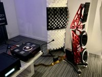
Room is 18 feet long, 14 feet wide, 8 foot ceilings. Semi-submerged room, so about 50% of the walls are concrete, as is the floor. Fairly thick carpeting, and standard sheet rock ceiling (the images make it look bad, it is just standard but thick stucco-like texture)

When I moved in, obviously an empty room...and it sounded TERRIBLE. I spent a few hundred dollars and hung curtains (as you can see) which was TRANSFORMATIONAL and made the room sound pretty dang good. If I clap in the room, very well dampened...is has the acoustics of a movie theater more or less.

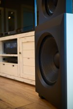
I feel I have mostly tamed the excessive highs. Bass is good (there is a big REL hiding in the corner, and it will shake the entire house).

Where I seem to have a little issue is some mid-bass resonance...think a few hundred hertz. I also would have no issue continuing to tame the highs a bit more.

Maybe I am leading the witness, but I keep thinking the ceiling could do with some acoustic paneling.
--Can't do anything to the floor, but it has thick carpeting, so that helps
--I do have a queen size comforter hung behind the curtain on the right-side wall (the biggest piece), and could certainly do more of that in the rear. The left side wall has a window, so I can do some but not all
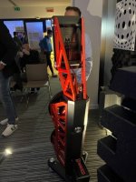
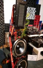
--Not much I can do with the front wall, but it is fairly 'busy' with stuff so hopefully that helps
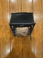
--If that back corner is a concern (where the black safe is), I could certainly put something there.

Suggestions for the ceiling...if anything at all? I would have no issue installing some lightweight panels (drilling, not gluing).

Thoughts, suggestions? Thanks!!!


Two Different Full Range Driver Wiring Help

Based on my search, I understand there may be some combing issues with using two full range drivers in the same design. I'm currently in the experiment and learn phase of speaker design. My current project is to make a small tower speaker with one front facing full range driver (the Dayton audio ps95) and one upward facing full range (Dayton audio ce65w) into an omnidirectional cone.

The drivers are both 8 ohm and I have an amp that will power down to 4 ohm. I was thinking it would be as simple as wiring the drivers in parallel, however, now I'm worried about power mismatching. My next thought was to use a double binding post and wire each driver to is own post, but I can't find any research on that.

I'm asking for wiring guidance and thoughts about my current project.

Thank you.

Schematic wanted for passive Crossover Unit of PMC's MB2/MB2s

Some attachments under
https://www.diyaudio.com/community/threads/diy-pmc-mb2-clone.310018/
and
https://www.diyaudio.com/community/threads/pmc-mb2s-clone.218042/
are unfortunately externally hosted and not upload here - thus no longer available.
Probably also the circuit diagrams of the associated crossover networks.

Maybe one of the member can upload this - thank you very much.

P.S.: according the attached images and those under
http://szymonfaber.pl/?p=1351
the parts for the crossover network unit mainly low-cost bi-polar elcaps and no air-coil inductors

Attachments

  • 15-1024x768.jpg
    15-1024x768.jpg
    184.4 KB · Views: 105
  • 16.jpg
    16.jpg
    151.3 KB · Views: 90
  • bb5(2).jpg
    bb5(2).jpg
    38.3 KB · Views: 78
  • images.jpg
    images.jpg
    9.4 KB · Views: 72
  • maxresdefault.jpg
    maxresdefault.jpg
    71.6 KB · Views: 74
  • IMG_0010.thumb.JPG.9b9efdec5bd1ec19b1ea533b22997c9a.jpg
    IMG_0010.thumb.JPG.9b9efdec5bd1ec19b1ea533b22997c9a.jpg
    194.1 KB · Views: 81

DIY-Danny & The Bad Cabs : Have Mic Will Trouble :)

Some interesting measurements on Cab vibrations further down his vid :

Login to view embedded media
Danny sellz tonz of Hi-Rez foam (not cheap!) , probably there are now more speakers upgraded with his stuff than unstuffed ones 🙂

Yes a Bad Cab can ruin your speaker completely no matter how expensive drivers your are using!

We need more research on how to build a trouble-free cabinet well worth the money!

Thick wallz will fix any cab problemz?

Well be prepared for 2inch thick chipboard TANX 🙂

Login to view embedded media

No brand polypropylene caps

hello,

I want to replace some old aluminium caps in several altec models cabinets (mainly axial 8.2uF) with polypropylene.

I contacted some electronic parts resellers and mainly I found no brand caps. Then I contacted "hifi" resellers, I was told to choose between no brand or golden price caps !

So I'm not even sure I actually have polypropylene capacitors and obviously no information about their structure 🙁

I think I'm going down on dubillier capacitors... Any advices or tips ?

For Sale Balanced Wayne’s Preamp with headphone outputs

I built this as an experiment and I loved it so much I’m building myself a dual mono version in a larger chassis.

  • 3 balanced inputs and one balanced output
  • Pin 1 is attached to audio ground so you can use xlr adapters for single ended inputs and outputs (attaching pin 1 to the chassis adds hum to the single ended inputs and headphone jack)
  • RK27 Alps 4 gang pot
  • Grayhill Selector switch
  • balanced headphone output
  • Single ended headphone output
  • VRDN PSU set up for wall wart
  • AC-AC Triad Wall Wart

Attachments

  • IMG_0970.jpeg
    IMG_0970.jpeg
    507.5 KB · Views: 179
  • IMG_0972.jpeg
    IMG_0972.jpeg
    466.8 KB · Views: 186
  • IMG_0995.jpeg
    IMG_0995.jpeg
    426.7 KB · Views: 185

Adcom GFA-5300 repair and restoration: DC offset issue

Hi Everyone,

A few weeks ago I rescued a broken, neglected, and abused GFA-5300. I now have the amp working, but can't get the DC offset adjusted to spec, and am hoping for some help on next steps.

To get the amp to this point I did the following:
  • remounted a dislodged transformer (the amp had been dropped)
  • removed years of dust and crap
  • changed caps (factory Lelons were bloated and leaking, with some hanging on by a single leg)
  • scrubbed and reflowed boards (the drop caused some severely cracked joints)
  • gently tightened transistor mounts
  • new thermal grease on the thermostat and bias transistor

Plus some bonus stuff:
  • changed trim pots to Bournes
  • changed input cap to Panasonic polypropylene
  • changed signal path resistors to metal film
  • cleaned up wiring
  • added IEC + earth loop breaker from Hoppes Brain

With those tasks complete, the following good things happen:
  • amp powers on
  • PS voltages are correct
  • bias adjusts correctly
  • plays music!

Unfortunately I can't get the DC offset adjusted correctly. I'm measuring with the amp warmed up, no load, and the inputs shorted. Instead of no more than +/-10mv (per the service manual), I'm getting 60mv on the right channel and 110mv on the left with the trim pots fully adjusted (DC values go higher if I turn the trim pots the other direction).

From what I've read in other threads, the IRFD210 LTP transistors could be suspect, in which case I'd have to source matched pairs. Is there something else I can try?

Thanks in advance

Attachments

My "semi" OB Project

Hello, this is my first OB project.
For the moment I have preferred to use a sealed box for the low frequency driver.
I don't have a dedicated room for the HiFi system, so I can't separate the boxes from the back wall as much as would be advisable, even so, I wanted to try something different from what I had previously built, and an open baffle caught my attention. .
The system is the following:
Beyma TPL150 for high frequencies from 1300Hz.
FaitalPro 10PR320 as a medium frequency driver from 180 to 1300Hz.
B&C 15PS100 from 32 to 180Hz.

The active system is filtered and equalized with a Minidsp 4x10.
I'm still in an adjustment period, but I like it...😆

I have carried out the entire carpentry and painting process in my garage, it has been a process of many months, but it has been worth it from my point of view.
I hope you like it.
Greetings.

Attachments

  • _DSC1825 1.jpg
    _DSC1825 1.jpg
    359.4 KB · Views: 223
  • _DSC1816.jpg
    _DSC1816.jpg
    369.7 KB · Views: 216
  • _DSC1824.jpg
    _DSC1824.jpg
    297.2 KB · Views: 213
  • _DSC1823.jpg
    _DSC1823.jpg
    316.3 KB · Views: 204
  • _DSC1830.jpg
    _DSC1830.jpg
    288 KB · Views: 213

Problems associated with a capacitive load

The speaker crowd have been discussing the merits of avoiding a load like this, and wondering why so many have done this blindly and apparently not had a problem.

What problems may happen and how would the uninitiated tell? What impedance threshold/frequency range should be considered risky? Are some amplifier types more susceptible?

h2.png
Projects by fanatics, for fanatics
Get answers and advice for everyone wanting to learn the art of audio.
Join the Community
507,773
Members
7,888,047
Messages

Filter

Forum Statistics

Threads
406,219
Messages
7,888,047
Members
507,773
Latest member
pete2000