Help me with my New Year’s resolution: finish one-project-at-a-time. Instead of buying everything I needed to finish a project, my bad habit of collecting exciting, new parts, passives and PCB’s as they appeared has left me with a cabinet of kits missing critical components. I want to sell the unused hoard to finance the missing pieces.
The prices listed are what I paid, less, or my best guess. All are unused/unsoldered and untested. Since I want to make fewer trips to the post office, a discount for multiple items or reasonable offers for bundles accepted. USPS shipping and hence the continental US strongly preferred; shipping will be calculated per order. I can send/post pictures as needed.
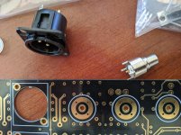
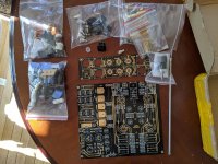
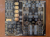
PCBs
1 Diyaudio F4 pcb, $12 for a stereo set
1 Pass Labs B1 stereo PCB, $14
Transformers
1 Antek AS-1212, 100VA, 12V output. $12
5 x Avel Lindberg 40/3010 47/400Hz potted transformers, 115V input, dual 9V@2A output. NOTE: THESE ARE 400Hz TRANSFORMERS. You cannot plug them into a standard 50/60Hz wall supply. Free if you pay shipping.
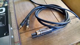
See pictures at
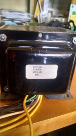
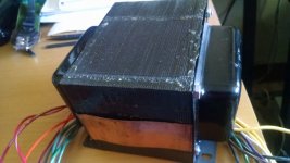
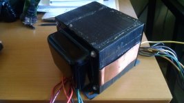
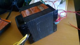
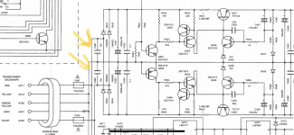
Power transformers, Plitron and other)
Caps (take them all for $50)
1 Hovland MusiCap, 1.0 microFarad, 200V, $3.00
2 Solen MKP-FC, 1.2 microFarad, 400V, $1/ea
2 Kimber KAP, 0.1 microFarad, 600V, $6.00/ea
4 Kimber KAP, 0.022 microFarad, 600V, $6.00/ea
2 MultiCap, 0.10 microFarad, 400V, $12 for a matched pair
4 Rel-Cap, RT series, 0.022 microFarad, 600V, $6 for a matched pair
4 Wima MKP 10, 0.22 microFarad, 630V, $1.00/ea
2 Vishay/Sprague Orange drop, 0.68 microFarad, 100V, $0.75/ea
2 Vishay/Sprague Orange drop, 0.22 microFarad, 100V, $0.75/ea
2 Vishay/Sprague Orange drop, 0.22 microFarad, 200V, $0.75/ea
2 Vishay/Sprague Orange drop, 0.1 microFarad, 600V, $0.75/ea
4 Vishay/Sprague Orange drop, 0.47 microFarad, 200V, $0.75/ea
2 Vishay/Sprague Orange drop, 0.1 microFarad, 400V, $0.75/ea
Other
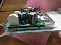
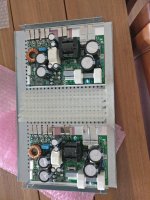
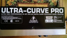
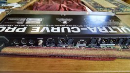
1 IcePower 50ASX2, 50W Class D stereo amp, non-bridgeable version, with wiring harness, $65
FREE if you order other stuff
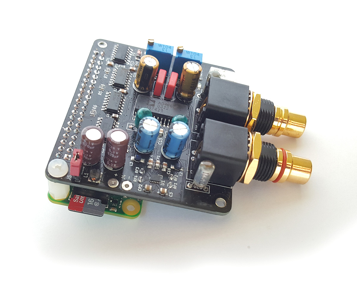
2 Raspberry pi rev B 2011.12, $9/ea or free
5 x Avel Lindberg 40/3010 47/400Hz potted transformers, 115V input, dual 9V@2A output. NOTE: THESE ARE 400Hz TRANSFORMERS. You cannot plug them into a standard 50/60Hz wall supply. Free if you pay shipping.
SOLD
SOLD -- 1 sets Diyaudio F4 pcb
SOLD -- 2 sets Peter Daniels F4 pcb
SOLD -- 1 Modified Linkwitz Crossfeed pcb (stereo, headphone use)
SOLD -- 2 Peter Daniels/Brian GT Mini Aleph pcb
SOLD -- Diyaudio Mezmerize older version), stereo pcb
SOLD -- 1 Zen v9 kit with Peter Daniels Zen v9 pcbs, 2 mono boards, 2 power supply boards, and a matched quad of LU1014D
SOLD -- 2 F5 kits, Peter Daniels stereo board, Mofsets - IRFP240/9240; Jfets - Linear J74/K170; Zeners - ZTX 450/550) from Hannes
SOLD -- 2 Diyaudio BA Gain Stage kits, stereo board, 2 matched pairs 2sj313/2sk2013 from Buzzforb
SOLD -- 1 matched quad Toshiba 2SK369GR, IDSS 8mA (grade B), from Hannes
SOLD -- 8 Vishay/Sprague Orange drop, 0.22 microFarad, 400V
SOLD -- 1 Plitron 077017000 2107 standard transformer, 300VA, dual 115V input, dual 30V secondaries


