Woofer on the side or bottom to augment 3way

Suppose you have a 3way (1 + 4in + 8in for example) design but want to augment the bass with an extra 10in or 12in sub woofer that will cross over at a fairly low freq. at about 80 - 100Hz.

Is there any inherent advantage for the subwoofer to be on the side or at the bottom of the cabinet?

Visually, with the sub woofer on the side, the cabinet could be made slimmer which improves the aesthetic.

But in term of acoustic, which would be better?

21st century Maida regulator PCB (with THINGY)

This PCB has a 21st century Maida regulator design along with Morgan Jones THINGY to elevate heater tube heater voltages. Populating the THINGY is optional.

I built this to use in tube preamps and it’s great. Low noise and great regulation.

I have 8 PCB’s spare for sale from a recent batch I had made for my own projects. The PCB is FR4 through hole plated with silk screen on one side and measures 80x90 mm. I updated my previous run to facilitate larger capacitors, wider package options for the LT3080 and higher voltage connectors.

This is based on the published regulator circuits from here DIY Audio and is not a commercial venture.

Combination of surface mount and through hole plated. All the maida regulator diodes and set resistors are SMD. Full circuit diagram and component layouts supplied.

PCB only £5
UK shipping £1 (contact me for international)

You will need to source mosfet e.g. STW12NK90Z and LT3080 regulator chip (DPAK, TO220-5 or SOT223, bridge diodes, reservoir electrolytics and trimmer pot plus THINGY components.
Send a PM with requirements.

Attachments

  • 20200307_164210-min.jpg
    20200307_164210-min.jpg
    917.5 KB · Views: 482

Speakers - raw drivers - B&W, Peerless, Dynaudio, others....

**** UPDATED ****

Clearing shelves in basement of projects that didn't happen. All drivers, parts work normally, sound great unless stated on specific line.

Message me with email for pictures if interested......

(4) B&W DM14 mid-bass / woofers. Rubber surrounds, each ~ 11 ohms DC resistance. Prefer to sell as a set of 4. Bowers & Wilkins. I also have DM14 cabinets for these (no grills, water stains on top). You can have these if you buy all 4 woofers and crossovers (but won't ship the cabinets). Asking $ 115 for set of (4) woofers. **** SOLD ****

(2) Crossovers for B&W DM14 speakers. 2-way with protection circuit. ****** SOLD *****

(1) Dynaudio - Volvo 8" woofer. Rubber surround. Some oxidation and little bit of rust on rear of chassis. 24W75 model I believe. 3" diameter voice coil (= 75 in model #). Asking $ 35

(1) Peerless (Polydax ?) tweeter from Spica Angeles (I think....). I think this tweeter is dead. Not sure if coil can be replaced. p/n D12x9D2 (I believe - fading ink is hard to read). Rectangular front flange. Soft dome. Asking $= make offer.

(1) Polydax (peerless ?) tweeter. Round front flange. DC resistance = 5.6 ohms. P/n HO12x9D25. soft dome. Asking $ 19.

(1) 6.5" woofer. Shielded magnet assy. It came from a lot of replacement drivers for mostly Canadian speaker manufacturers (Mirage, Paradigm, etc....). All I can provide is the #'s on back of driver. 709009 (either p/n or s/n) also: W6.5-13.5 P/S Paper cone, rubber surround, semi-mesh center cone (see-through). It has a plastic mounting ring that cover mounting screws as well. Measures ~ 3.2 ohms DC resistance. Asking $ 25.

Message me for pictures if interested in any item.

I will likely be going through my vacuum tube boxes and posting an ad(s) for some of the extras that I have in the handful of boxes of tubes.

I can ship to USA or Canadian locations. I package items extremely well for shipment. See my Ebay profile of same username. I will accept Paypal, unless you have cash and want to meet me in Baltimore - Wash-DC area.

Thanks !!!

Passive radiator design from scratch

Are there any guidelines to design a custom passive radiator from scratch?

My intentions are to make a honeycomb passive radiator membrane, resulting in a known Sd and mass (Mmd). I've several idea's for the suspension that I'd like to try out, that hopefully ends up with a ball park Xmax of 10 mm for the passive radiator.

My first try would be a 33 x 33 cm square membrane (1089 cm^2) with an Mmd translating to the equivalent of a port that is between 100 cm - 150 cm long (40 - 60 inch). This will be used in combination with a 12" PA driver, in an enclosure tuned to 50 - 60 Hz.

What I do not know at this point are the resulting Fs, Vas and Qms and the effect these will have on the performance of the passive radiator.

I've seen mention of the effect of the Fs on the passive radiator performance but nothing on the effect of the Vas and Qms. Any guidance is welcome 😉

improvements parallel cap construction for crossover network

Hi. Is there any advantage to using multiple small capacitors, instead of one large capacitor, in a crossover network.

I'm wanting a 3uf capacitor for a tweeter, should i use one 3uf, or 3 x 1uf. Also, is there any point to adding a small 0.2uf teflon to the parallel stack. Some people are reporting good results.

The capacitor i am thinking about is the k71-4 polystyrene nos from russia, and ft-3 teflon

Thanks

Holy blast from the past.

I haven’t logged on since some time in 2011. 9 freakin years.

Hmm, what’s new with me? I moved to North Carolina after a brief 5 year stint in Pennsylvania. I put down my wrenches and picked up a set of micrometers. Becoming a Machinist has been a wild ride.

I bought my first house last year. That has been a hell of an experience.

At any rate on to my current audio state.

My current list of jun.. equipment includes:

Preamplifier:
Linn Pretek (not running, power supply issues)
Linn Kairn (runs intermittently, bad voltage regulator)
Hafler DH110, currently in use.
Heathkit AA-141 (needs to have a few tube sockets tightened up, a couple tubes in the Phono section replaced, and some new coupling caps here and there.

Power Amplifier:
Not one, but TWO Heathkit AA-121s. This is the amp that brought me here in 2010
Hafler XL600 (The largest and most powerful amp ever made by David Hafler.)
Two Hafler XL-280s

Turntables:
Thorens TD-160
Revolver with Linn tonearm

Sansui SE-7 10 band (I think) EQ

Pioneer RT-707 tape deck

Speakers:
Klipsch Forte
WTB Klipsch La Scala (cash in hand....)
Polk M10’s

That’s about it for the stuff that is currently in rotation.

An interesting thing of note: I recently noticed a patent number on the back of the Heathkit 121 amps. I pulled the patent, and it was for the ultralinear AB1 amplifier circuit, designed by David Hafler, before he formed Dynaco, which he later sold to found Hafler. Who’d have thunk it?

Considering a 2.1 Design

I am contemplating a new set of speakers for music reproduction.
For deliberation will be a 2.1 sealed enclosure system.

Listening Room Dimensional Parameters:
Depth = 148”
Width= 140”
Ceiling height = 108”
Face of baffle will be 20” off of front wall.
Ear position will be 120” off of front wall.

After surveying drivers to use as a woofer along with some tweeters for the 2-way portion of this design, I came up with the following combinations to choose from or advise against:
Visaton B 2oo / Dayton RST28F
Visaton B 200 / SB Acoustics SB29DAC-C000-4
Wavecor WF166TU02 / SB Acoustics SB29DAC-C000-4
Fountek FW146 / Hiquphon OW1

For the subwoofer portion of the design, the Peerless 12” 835017 looks like a decent candidate.

General Considerations and Approximations:
Sometimes, I may Listen at ~ 92 dB. In round numbers there is ~ 10 -12 dB drop due to distance.
Therefore, output will need to be ~ 104 dB
Thus power amp requirements will be around 65 watts for Spl of 86 and 25 watts for Spl of 90.
I am undecided as to passive or active crossover. Leaning toward active, but I haven’t done much research lately to see what’s available.

Power Supply troubleshooting.

I have a crown CDi1000 amplifier and it seems the power supply is the issue. When the power switch it set on, nothing happens. No lights, no fans. Pulled the cover off, and check the primary fuse. That was fine. I found one area of the board that is suspect. The board was browned as if it had gotten warm/hot in that area. I checked the 3 transistors in the area and they were not shorted. They were a MPSW42 NPN-transistor. There were a couple of resistors in the same area that looked like they had gotten warm, but tested fine as well. I probed around and found that all the larger size caps have a DC voltage on them as well.

At this point, I don't really know where to go to find the issue. It seems obvious that it is a power supply issue, but could a failure in the amplifier down line be the issue? Any help would be appreciated. I've attached some pictures of the power supply section. Let me know if I additional pics would help. Thanks!

Picture 1 : The area that the board was darkened
Pictures 2-4: Power supply section.


Link to transistors I tested
http://www.onsemi.com/pub/Collateral/MPSW42-D.PDF

Attachments

  • 1.jpg
    1.jpg
    282.5 KB · Views: 428
  • 2.jpg
    2.jpg
    186.3 KB · Views: 367
  • 3.jpg
    3.jpg
    176.7 KB · Views: 330
  • 4.jpg
    4.jpg
    186.8 KB · Views: 349

DC offset in class AB power amp

Hello,
I have a 70's solid state amp on wich i measure about 400mV at the speaker output. I don't think its good for the speakers ?
I managed to get rid of that DC voltage with 2 big electrolytics caps minus to minus, it works but i think i might be loosing some bass (330uF caps ; 2200uF are on order for further testing).

I wonder if there are other ways to reduce that DC ? Maybe a trim pot somewhere ?

Thanks!

Attachments

Electronic Circuit Breaker Variac Isolation Transformer Combo

Greetings from a new member.

I have posted a video on YouTube describing the design and building of an Electronic Circuit Breaker (including schematic, PCB, BOM and Gerber files available) integrated with a Variac and Isolation Transformer in one 3 unit rack mount case. This equipment setup would be quite useful to anyone building, repairing or testing audio gear, especially tube circuits.

The electronic circuit breaker is based entirely on the Glasslinger circuit. It features an adjustable current limit (200mA to ~7 amps) and adjustable sensitivity (2 (~32msec) , 4, 16 or 32 cycles above the current limit) and is much faster than a fuse or mechanical circuit breaker. It uses a LM311 comparitor and a CD4040 binary counter to trigger a MOSFET that activates a cutoff relay.

This is my first YouTube video, feedback welcome! I hope you enjoy it.
Video Link:
YouTube

Attachments

  • IMG_7093.jpg
    IMG_7093.jpg
    719 KB · Views: 363
  • IMG_7060.jpg
    IMG_7060.jpg
    805.8 KB · Views: 321
  • IMG_7079.jpg
    IMG_7079.jpg
    1,002.6 KB · Views: 273

Question about ebay in Germany

An older test meter caught my eye on ebay but it was in Weissenburg, Germany and the seller was not shipping to United States.

My question, has any of the members found a way around this?

I understand why a person wouldn't want to ship internationally, but I am truly interested in purchasing this meter if there is a possible way.

Thanks for any assistance you might share.

Seeking Guidance - 45 Parafeed Headphone Amp Design

Hi friends,

I am hoping to get some other eyes on a design I am working on. This is only my second and I am new, had help with the first from a gracious DIYer, trying to put the knowledge gained to work on my next one, any input is appreciated. I apologize in advance for the book-long post, I make no assumption that I should/will receive any assistance, but if you read on and are willing to give your input, you are a saint.

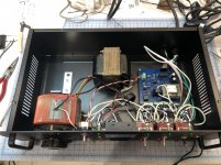
In general, it is a 6J5 input, 45 output parafeed headphone amplifier. Both stages will be cascode CCS loaded, planned output transformers are Sowter 8665. Mains transformer will be custom-wound by Sowter as well, targeting 300VAC HT secondary right now. DHT filament regulators will be Rod Coleman, including his raw DC supplies (not shown in the schematic)

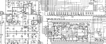
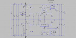
Here is my draft of the amplifier schematic:

45 Parafeed Amplifier.png

Draft of the HT power supply schematic:

45 Parafeed PS.jpg

Notes on the amplifier schematic:
Plan to leave the 6J5 cathode resistor unbypassed, modest loss of gain on my LTSpice model with the CCS load in parallel with the 470K grid leak
Leaving the 45 cathode resistor unbypassed as well with the OPT grounded at the top of the cathode resistor, an "ultrafeed" configuration. My understanding is the opposite phase AC signal here will cancel and prevent cathode degeneration. LTSpice model seems to agree here too
Cascode CCS are the IXTP08N100D2 top device and IXTP08N50D2 bottom device offered by K&K audio. The 6J5 CCS will use the included 3W heat sink. As of right now, I am hoping to mount the 45 CCS to the aluminum chassis (K&K has a kit for this express purpose), it will need to dissipate ~6W​

Notes on the power supply schematic:
Plan to use 600V Nichicon electrolytics for C1, C2, C3: https://www.mouser.com/datasheet/2/293/e-lgn-1511829.pdf
Lundahl chokes are likely overkill, I understand parafeed has very high PSRR, unsure how much filtering is necessary given the OPT will have a low turns ratio since this is a headphone amp
Diodes are fast-switching, soft recovery types from Vishay, VS-HFA06TB120-M3
I plan to add some sort of inrush current limiting, perhaps NTC thermistor, TBD
According to PSUD2 model, this supply yields 10mV peak-peak ripple at the top of the 45 CCS, 2uV peak-peak ripple at the top of the 6J5 CCS​

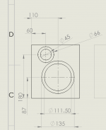
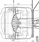
Here is where I am having some trouble...choosing a load line/OPT turns ratio. The Sowter 8665 has a 137H primary inductance, a 10K primary with the ability to wind for three different secondaries, 12:1 (65ohm), 6:1 (260ohm), 3:1 (600). I use 300ohm headphones, primarily.
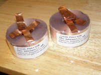
Sowter 8665: SOWTER TYPE 8665

Given this is a headphone amplifier, and the power supply is already quite inefficient given the CCS output load, I am opting for a 180V 31mA bias point for the 45.

The way I am coneptualizing these load lines - the "infinite" AC impedance of the CCS on the ouput is in parallel with the OPT primary, such that the full load seen by the tube is essentially the primary impedance, for calculation purposes.

When it comes to the peak-to-peak voltage swing at my 180V 31mA bias point, the positive grid swing will be limited by the 0V grid curve, and the negative swing will be limited by the B+ at the top of the CCS (minus some headroom for the CCS drop out voltage, ~10V). As such, the 0V grid curve is the first of these two limitations and dictates the peak-peak swing.

With all of that being said, a 300ohm secondary will give the following impedance ratios with the three different turns ratios:

12:1 >>> 46.2K:300, ~16ohm output impedance with 45 ra = 1650, P into 300ohms = 150mW
6:1 >>> 11.5K:300, ~47ohm output impedance, P into 300ohms = 400mW
3:1 >>> 5K:300, ~103ohm output impedance, P into 300ohms = 757mW​

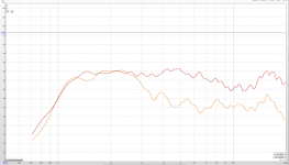
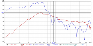
The load lines for these three windings, my 45 bias point, and 300ohm secondary are below. Here is an example of how I came up with them, with the 12:1 winding ratio:

10K:65ohm = 154:1 impedance ratio = 42.6K:300ohm
V = 31mA x 46.2K = 1431V (to determine slope of the load line)
Output impedance = (1650ohm ra of 45 / 154) + 4ohm DCR secondary resistance of Sowter 8665 = 16ohm
Peak-peak voltage swing = 226V, 226V/(2sqrt(2)) = 80Vrms, (80*80Vrms)/42.6K = 150mW​

Assuming all of that is accurate, which may be a HUGE assumption 🙂 here are the load lines in red, bias point in green, peak negative swing in orange, max anode dissipation in purple:

12:1 winding ratio, 180V, 31mA, 46.2K

45 Parafeed - 46.2K load line.png

6:1 winding ratio, 180V, 31mA, 11.5K

45 Parafeed - 11.5K load line.png

3:1 winding ratio, 180V, 31ma, 5K

45 Parafeed - 5K load line.png

There is some concern on the 12:1 46.2K load line, as it passes above the max anode dissipation on the negative peaks, however, given the tube will clip at 0V grid much earlier than this (not to mention I would be deaf), is this truly a concern?

The crux of my problem is which winding I should be using for a 300ohm load, and if there is anything else I am overlooking (quite likely).

The OTHER major question, which I believe will need to be answered via experimentation, is the size of the parafeed cap. I understand there are ways to estimate its value using choke load, but for CCS, I don't believe there is. I came across a post by Paul Joppa of Bottlehead stating that there is no reliable way to calculate the parafeed capacitor size for a CCS load, but to try various sizes and take frequency response measurements.

If you have gotten this far, thank you!!! I hope this is not a tall ask to have someone else look over my work, but I am a firm believer in learn-by-doing, some of this information is not easy to come buy, been at it for three months non-stop, and I am no engineer :/

Thanks again.

Recomended L Pad or resistors?

Hi all,

Working on my new speakers with a JBL 2452SL that needs dropping in volume by 20db vs a TD10m as its producing a little too much hiss (Hypex Fusion NCore amp)

The driver is a 150w capable unit (not that I ever expect to be maxing this out)

Do you recommend a L-pad or soldered resistor version? most resistors seam to be much lower power (5w),although its for domestic use, I assume this is not enough to run safely?

Thanks.

7189 PP amplifier

I need some help understanding this circuit. My issues are with how the 5879 is set up.

1. The plate supply resistor is 180K while the suppressor is 120K, so won't that mean the Plate voltage is lower than the suppressor voltage?

2. There are no AC bypass caps on the 6CG7 grids. So won't there be plate voltage here?

3. How is phase inverted on the 6CG7 grids? They are tied together with a 1.5M ohm resistor.


89011d023b7c203b406d7c71e9bcf84c.gif


7189 PP1

Polam / Telam tubes !

Hey guys

I read some articles about the qualities of Polam and Telam EL84 tubes, being considered by some as the best produced EL84.
The POLAM / Telam is a Polish manufacturer of tubes, part of the Philips group.
During World War II it was occupied by the Nazis and I believe that German technology has been incorporated into the production.
The plant in Warsaw was abandoned due to contamination by mercury.
Then I got some POLAM EL86 to test on a prototype. The construction of this valve is excellent, has thick glass and aligned plates and appearance reminiscent of German Telefunken and RFT tubes.
I biasing these POLAM in single ended classe A and to my surprise, with a 2Kohms output transformer, they played very well.
Well-balanced, fabulous mids, very strong bass and excellent trebles.
This excellent POLAM EL86 plays much better than my Mullards EL84.
Now I want to see if I can some POLAM EL84 to try.
Nice and very recommended tube.
See the abandoned factory of Polam:

Enter & Die: 52 Photos of a Poisonous, Abandoned Factory | Urbanist


Aldovan

Kicker 083ZX1000.1 output trouble

OK so I am starting a zx1000. 1 amplifer seems to be running in perfect order. 13.3vdc it draws after the relay engages 1amp of current. Regulated voltages are present on the class D card and the input card. I traced my 40hrz from input to class D card as well.
So I checked u202 pin has a nice triangle wave. No driv from. Pins 8&9 so I'm thinking its the ic that's bad?
So when I changed it the amplifier started flashing in and out of protection.

Attachments

  • 15827426684175200568444313691249.jpg
    15827426684175200568444313691249.jpg
    1 MB · Views: 129
  • 15827426910394415775677953761716.jpg
    15827426910394415775677953761716.jpg
    1 MB · Views: 130

Help in understanding this baffle effect

Hi
I mounted a tweeter "dayton-audio-ND25FA" once in a test box where i tested the mid and one in the final box design. (the test box was intended to the the mid only but i mounted the tweeter to get an idea of how this speaker will sound)

See attached measurements and images.

in the test box it case a and in the final box it is case b.
in the measurements the orange is the test box (case b)


Case B looks very bad. but it does not look like baffle diffraction loss.

just a note on the image you see with the final box:
it is on a shelf close to the wall because i want the destine the xo with measurement of how this unit will be placed when it is ready.

when removing the shelf it did not to any effect on the tweeter measurement (as expected i guess)

Thanks
Ran

Attachments

  • tweeter.png
    tweeter.png
    116.8 KB · Views: 165
  • Case A.jpg
    Case A.jpg
    832 KB · Views: 165
  • Case B.jpg
    Case B.jpg
    728.8 KB · Views: 158
  • dim.png
    dim.png
    38.1 KB · Views: 173

FS: pair of Transylvania Power Company "The Tube"

*** SOLD ***

These unusual devices are more a waveguide than a horn. They consist of a 5.3" long slotted tube made for a 1" bolt-on compression driver with 2 or 3 bolts. They can be used from about 1kHz-20kHz with a fairly uniform response and wide dispersion. The mounting plate is about 4" x 6".

They are made of 0.125" aluminum, anodized black.

They are in good condition, with a few small scratches and dings from normal use.

I have yet to pack them in their shipping box, but it'll be fairly small and light, so freight cost should be decent. I can ship to Canada and US.

I'm asking for 150$CAD for the pair. I accept PayPal.

back_insc.JPG

backs.JPG

front_a.JPG

front_b.JPG

front_insc.JPG

fronts.JPG

tops.JPG

*** SOLD ***

veneer on recessed tweeter

I have a lot of woodworking and furniture building experience, but mostly in solid wood... I am new to veneer. I have a problem that has stumped me.

Let's assume I have a baffle of MDF or plywood, and I have cut my tweeter hole of 75mm, and I cut a 3.5 mm deep recess for the tweeter flange which is 105 mm diameter.

Now I veneer the baffle. How do I cleanly cut the veneer to match the recess? The depth of the recess is only 3.5 mm (about 5/32 inch), so I don't see how I can use a laminate trim bit. I also struggle to see how a veneer saw or utility knife can negotiate the inside curve of a 4 inch circle and make a clean cut...

One solution is to veneer before cutting holes... but that seems like the wrong order. I generally cut driver holes early in the process, and veneer at the end... ???

Obviously I am missing something... thoughts?

Martin Logan Montis Power Supply Board Help

Hello all,

Anyone have any connection info on these power supplies - I believe they are common on the tier of ML Speakers - Montis, Vantage, etc.

I have two of them and need connection info - I see two small headers with 5 -- 6 pins, one three wire connector block, and two spade connections - My guess is the spades go to the speaker inputs to for sense circuit, but other connections are in question - wanted to use these power supplies for an ESL (CLS Panels) experiment.

Thanks!

Audison Voce 5.1k disorted Signal

Hello, i have a Audison, on the Channels A ( A-Class) i have i disorted upper Sinewave, on the right channel its the lower sine wave. I expect a problem in the preamp board. It doesnt change, if i move any switch or HP switch. When the amp heats up, it becomes more. Maybe somebody had this failure allready. Also the Sub Channel is damaged, but i removed the Drive board for that channel, and the amp runs fine for a year. Maybe also somebody know something.

Attachments

  • IMG_20200307_153313.jpg
    IMG_20200307_153313.jpg
    1 MB · Views: 97

Variacs

I've been collecting bits and bobs through the years, but never had the space to use them till fairly recently. Some these bits are a variac and isolation transformer.

I've inspected the variac, looks like it has two adjustments, the big knob with a pointer and the plate beneath that which you can turn as well, it has a carbon brush.

Can any one tell me what that supposed to do?

I need to work out an enclosure for it, any ideas? The thing weighs about 6Kg, there are three screw hole on the bottom.


https://ibb.co/jJ00d2w

Which Woofer for 10P WAW?

Howdy all.

I’m planning a Woofer Assisted Widerange project and would appreciate some thoughts.

The wideband is an Alpair 10p. Is there any rule of thumb regarding size of woofer to suit this? The plan is to cross over to a woofer at maybe 250Hz give or take, and then to hand off to servo subs in the 50-80Hz range.

I do like the impact of larger woofers, but would smaller woofers have greater finesse? Finesse is more important (to me) than impact, if there has to be a trade off.

Options are to use the 15” Faital Pro 15PR400, or potentially to sell those and use either single or double 8” Peerless HDS Nomex drivers per side. Another option is a pair of Seas Excel W17CY001 per side. Enclosures will all be sealed, actively driven and XO’d/EQ’d with MiniDSP.

If using the 15”, the woofer will be side mounted to keep the enclosure narrowing. If using smaller woofers, they will likely be front mounted.

Any thoughts appreciated.

Cheers,

Matt.

FS Marconi TF2331 Distortion Meter.

For sale, Marconi TF2331 distortion meter, operating and service manual and low distortion 1k spot frequency oscillator, all you need to measure audio amplifier THD. Will run on AC voltages of 190 - 260v, 95-130v @ 40-500hz & 18-45v DC

The TF2331 measures signals 1 - 30v (but can measure higher voltages) 20hz to 20khz down to 0.01% THD ( you will need a +15v 0v -15v PSU though, or might be able to chuck one in)). The manual covers all measurements in detail. The 1khz (ish) Wein bridge oscillator has a THD of 0.0025% THD, for more details etc see - YouTube

I'm asking £100, shipping within UK included. Will consider shipping to Europe and maybe other countries, but might cost a little extra, drop me a PM for details. It will be well packed and boxed up.

Andy.

Attachments

  • DSC02242.JPG
    DSC02242.JPG
    161.7 KB · Views: 139

New pair Alpha-Core 1mh 14 AWG Copper foil inductors

Hi All,
I have an unused pair of GOERTZ/ALPHA CORE 1mh 14 AWG Copper foil inductors to offer.

*Perfect condition, never used.*
Each weighs ~550g
Dimensions are 70mm diameter x 35mm high

New price is around $70.00 the pair in the US. (Madisound price)
Offering these at just GBP20.00 for the pair + shipping (under half of the new price)
UK shipping GBP5.00, Europe GBP12.00 (airmail)


Please send a PM if you'd like them
Thanks
Rob

Attachments

  • P1010349.jpg
    P1010349.jpg
    566.4 KB · Views: 254

3rd order bandpass designs?

I read somewhere where someone built a 3rd-order bandpass box. it looked similar to a normal bandpass, only it had 2 ports, each one of a different size. I wanted to know more about this design, and if anyone else had seen, built, or knows how to build one. anyone know any good sites/resources for odd box (not ported/ passive radiator/ sealed/ 4th or 6th order bandpass)

True resolution

Lot of measurement graphs are so smooth that they almost looks like they are made up, like REW graphs looks amazingly fancy and smooth, but when looking at graphs made with hiend measurement systems like Klippel they look always a lot worse and i think more accurate

If a measurement due to setup has a low resolution of 200 Hz, is it not better to just show every true measurement point and nothing in between?

Diy Show Stopper: supreme court sales tax

I do a lot of experimenting with audio. A large part of keeping the cost down has been minimal sales tax, allowing a bad design to be discarded and re-started.
Since Jan 1, 2020 my online buying has tapered off to nearly zero.
Now sales tax is on everything including shipping etc.
Buying ebay 'for parts only' heavy tube chassis etc now too expensive.
The tax laws state to state are so convoluted even tax professionals cannot guarantee compliance.
The tax laws effect craft shows, bazaars and I see garage sales being included eventually.
Definately is killing my diy hobby.

Maybe a 'Church of Audio' with 501c3 tax exemption is necessary.

Wiring line level in ceilings to a central location

I'm building a new home and wanted to put amplifiers mixers in a central location. My plan was to wire line level signals through ceilings from each room into my cupboard under the stairs.

I've set up a test in our current home (except with AMP in the living room, not in the central location):

1Wn97XE.jpg


I haven't used a balun or DI box, and there isn't TOO much hum and hiss, it's manageable.

But something strange is happening with the audio from Alexa, it sounds really bad: a lot of hiss and distortion. When you turn the volume down, the signal to noise is so bad that the hiss is really high, also the distortion doesn't really disappear it just gets quieter.

When I unplug the Alexa and swap it out for audio from my phone, it sounds really clean. So you'd think it's a problem with the Alexa. But...

- I tried another Alexa and the same problem happens.
- I turned the Alexa up (and mixer input down) to increase signal to noise, it didn't help
- I turned the Alexa down (and mixer up), this just makes the hiss relatively louder
- So then I plugged the Alexa directly into the amp and it sounds really good
- I plugged the Alexa back and tried it in a battery pack, rather than into the USB power supply, and the problem is still there.

When I say there's a lot of hiss, it's really intense when the Alexa starts up. And the phone has very good signal to noise, hardly any audible hiss, and it's not distorted.

Should I be using baluns, or a DI box or something like that?

I've heard it's fine sending line level signals over CAT6 - indeed with the phone plugged in, it's all good.

Finally, what should I do when wiring the new home up? Should I avoid this complexity and keep wiring local? I really want to aim for whole-home audio, and the audio mixer I am using is a matrix mixer so I can plumb any number of inputs from any room into any number of rooms... which is really good. That's why I'm trying to do it.

Any ideas?

Ba3 for F6

Just finished the F6 and though I have an updated McCormack pre amp to use temporarily I'm eying making a pre-amp. Am I right that the BA3 seems to be a great match for the F6 and that it puts out enough signal to adequately drive it ?

If so, is there an updated BOM somewhere here that can be a starting point for me ?

I'd want to build the active version.

thank u !

Transfer Function - Measurement and Use

I'm considering a new subwoofer build for my daughter's car which we're planning to spiff up a bit for a car show coming up in June. As a first step in building a subwoofer for any car, I first measure the car's transfer function, to get an idea of what to expect when a subwoofer is mounted in the car, and also to use the transfer function as a "guide" to choose the best subwoofer design for the car. I thought I'd document the process here, just in case anyone's interested.

First, tools required:
1. REW (Room EQ Wizard)
2. PC with a decent soundcard and a mic (doesn't even have to be a GOOD mic)
3. Subwoofer driver mounted in a sealed enclosure
4. External amp to power the subwoofer

Step 1:
Use REW to obtain the close-miked response of the subwoofer driver in the sealed enclosure. Call this measurement B.

Step 2:
Place the subwoofer in the car, in the location where you're planning to place any subwoofer that you're going to build for the car. Place the mic at the listening position (e.g. just in front of the driver's seat headrest). Use REW to measure the response. Call this Measurement A.

Step 3:
In REW, in the "All SPL" window, use the "Controls" feature to adjust the level of measurement B until it crosses measurement A at or above 100 Hz (car audio cabin gain typically starts below that). Make select the "add offset to data" option when you've finished making the adjustment.

Step 4:
Using REW's "Controls" feature, generate the transfer function by selecting measurement A for option A and measurement B for option B under the "Trace Arithmetic" section, selecting "A/B", and then clicking on the "Generate" button. A new measurement will be generated, called "A/B". This should be the car's transfer function.

Note: The generated transfer function will likely not show up under the "All SPL" window, because its dB range is going to be substantially lower. You'll need to select the "SPL & Phase" window in order to see it.

Do this right, and you'll end up with something looking like the second picture that I've attached 🙂.

Attachments

  • 20200310-Close-miked vs in-car.png
    20200310-Close-miked vs in-car.png
    40.8 KB · Views: 308
  • 20200310-Transfer Function.png
    20200310-Transfer Function.png
    35.8 KB · Views: 284

My 2.1 amplifier design using a TPA3255

Hi all,

I just finished the PCBA design for a 2.1 amplifier using a TPA3255. The order has been placed at JLCPCB, and I will try to keep this thread up to date. Some specs:

- 2 x 50 Watt, and 1 x 100 Watt for the sub. The TPA3255 could deliver more power, but this increased THD dramatically. Also, I don't need more power.
- Post filter feedback implemented to improve audio quality
- Microchip BM64 bluetooth module with an external PCM5102A DAC.
- Low, high and loudness controls
- 4th order adjustable (in both frequency and volume) subwoofer crossover
- 2 aux inputs

All opamps are LM4562. It can be powered with a voltage from 24 to 36V. It will be used with a set of Overnight Sensations. I would like to add a subwoofer, hence the 2.1 amp. The top layer of the PCA is included in the attachment. When the PCA arrives I will place an update with a review of the quality. Since JLCPCB is incredibly cheap I am a bit suspicious. It is a 4 layer board, most of the SMD components will also be placed by JLCPCB.

Attachments

  • 2.1 pca.JPG
    2.1 pca.JPG
    168.2 KB · Views: 278

Garage Sale / Yard Sale - Lots of Stuff (Part 3)

As I continue to clean out my workroom...

Transformers:

One Shielded EI Core transformer, 37-0-37 secondary, nice copper shielding, weighs about 7lbs $15.00, ships in medium flat rate box.

IMAG0118.jpg


Electronic Parts:

Auricap 450V, 1.5uF Capacitors, Excellent Condition, $20 for the pair. Ships in a small flat rate box.
IMAG0168.jpg


Copper Foil Air Core Inductors:

Two of 2.2mH 14 AWG - $20.00 Each
Single 3.9mF 12 AWG - $40.00
Single 0.68mH 16AWG - $10.00
IMAG0171.jpg


Ring-Lit, Flush Mount Push-Button Switch, 24Vdc Contact, Amber... $5.00
IMAG0170.jpg


Two Project Boxes with end-plates. They are identical to these:
Penn-Elcom R1197/100 Heat Sink Box 4.13" x 2.36" x 4" L
$5.00 Each with the end plates.

NAP-140 Clone Kit, $50.00, should fit in a medium flat-rate box:
IMAG0166.jpg


OTHER STUFF:

Seas Coaxial-Mount Tweeters. These can be adapted to fit inside any of their 29mm diameter VC Woofers, like the W18, W22 etc. Two are in pristine condition, one lost a lead (but the VC Leadout is still there and accessible) and has the mounting post removed (you will have to do this anyway to mount them in the woofer). $25.00 each for the good ones, $15.00 for the one with the broken lead. Ships in a small flat rate box.
IMAG0131.jpg


Medical Grade 1:1 EI Core Isolation Transformer - 440VA, has a 2.5A breaker installed, I added some X-Caps and a CMC to it, sounds very nice for source components and preamplifiers. Probably vastly under-rated as it weighs at least 15 lbs, $30.00:
IMAG0172.jpg

IMAG0173.jpg


Damping Materials, this is like BH5 or SonicBarrier but much better, it includes two of the mass-loaded layers, I don't think this is commercially available anywhere:
IMAG0167.jpg


I have several pieces of this as follows (All in inches):
18x15
6x58
12x22
18x26

Single mass-loaded layer:
18x24 (4x6" rectangle cut out of one corner)

$10.00 per square foot. Depending on how you can tolerate it being cut, I can ship in flat-rate boxes or custom sized boxes.

Flat Rate Boxes in the US:
Small are about $5.50
Medium are about $11.50

They go up to other countries, but not too much, maybe as high as double. I can ship them anywhere needed.

E-Mail and Paypal to pkhilgeman@gmail.com

Thanks for looking

Which PCB For This Transformer

WARNING: This is an extreme newbie question;

Which PCB should I use for this transformer (see attached photo).

I'm going to build a small tube amp and this is the power transformer that the 120vac electrical wall outlet will be wired into.

What i'm trying to learn is whether or not there are common and commercially available PCB's for such transformers or if all such transformers would require a custom made PCB (in my case custom order...because i'm not going to DIY the PCB).

The pins are 0.300 inches apart from the center of one pin to an adjacent pin. And the pins are very rigid posts that you'd not be expected to solder wires onto. Therefore it seems to me that there must be some other common method of connecting to these pins like a common and commercially available PCB that has holes which are 0.300 inches apart or some kind of module that these types of transformers just plug into.

Basically, for a newbie DIY guy, what are some of the cheapest ways (and hopefully the simplest ways) to get this thing wired into my tube amp?

Kind thanks,
Eddie

Attachments

  • power transformer pins.jpg
    power transformer pins.jpg
    201.2 KB · Views: 107

Help about DIY DAC

Hi,

I'm new here and in the world of DIY audio system.
My current setup is an Atoll IN80SE amplifier, A pair of JBL TLX16 speakers, A Cambridge DACmagic 100, a YAMAHA CDX 397MK2 CD player and a RPI4 for digital music.

I would like to make my setup a bit more DIY and replace my current DAC to a better sound quality with better components solution.

But i don't really understand the world of I2S, HAT, USB signature, Digione...

Where can i learn a bit more about RPI DIY system ? Maybe with explanations about which role have each cards.
Which cards are needed to replace my current DAC ?

As example : I recently discover the sparky bundle (kali reclocker, allo piano 2.1, galvanic isolator....) The bundle seems to be appreciate by many pple. But:

Does RPI audio system are good enought compare too dedicated solution ?
Will i gain in sound quality compare to my cambridge current DAC ?
Does the kali reclocker, allo galvanic isolator, the piano 2.1 44/48 are compatbile with my RPI4 ?
Is it necessary to add the volt amp if the piano card is connected to my Atoll amplifier ?
Is it necessary to add the Capacitance Multiplier if i don't use the volt amp ?

Thanks you for your answers and clarifications

Small full-range driver

Hello,

I want to start learning how a DSP works and what I can do with it. I'm planning on buying the dayton dsp-408 and Minidsp umik-1 as my measuring mic.

As for a driver I'm looking to buy 4 small drivers (around 100mm in diameter) so I can experiment with the placement of the speakers, eq the speakers themselves, tinker with room correction and so on. When I'm not tinkering, I would like to be able to enjoy the general quality of the speakers themselves by listening to some music.

I'm in doubt between the PS-95, ND91 and RS100 from the dayton drivers. If I'm simply looking at the frequency response graphs, the ND91 seems to be the easiest one to work with. It even seems to be smoother than the RS100. Generally speaking, the RS-line is considered a 'better' speaker but I can't seem to find direct evidence of that in the frequency response graphs or the impedance/phase. The PS-95 is the best looking speaker but the frequency response looks just awfal. How on earth do I decide what driver to use?
Help me out!

Kind regards

FS: MFOS-WSG Synth Kits (Music from Outer Space Weird Sound Gen)

Some time ago I built circuit boards and bought parts to make three Music from Outer Space WSG kits. I built up one for myself and the other two sat on a shelf.

The WSG is a compact six-oscillator, four-voice normalised analog synth with a very effective filter.

But I still have the two kits and they need to find homes. The kits contain: All necessary switches, pots, jacks, knobs & hardware plus a built circuit board. You supply your own case / panel and wire.

Asking $35 each, plus shipping (cheap).

MFOS-WSG-Kit-01.jpg


MFOS-WSG-Kit-02.jpg

Iwata for TAD 4003

Hi everybody,

Me and a friend are to build the Iwata's, but for the TAD 4003 driver, which is quite different to the 4001 in throat-size.

I downloaded the old drawings from this site and -angle and was worried about, if TAD had gone different ways in terms of the angle. I used Illustrator to make the following drawing (4003 overlaid by 4001) to show, that it should be in terms of the laws to make a adapter.

The "start" of the Iwata-horn lies perfect in the middle of the diapraghm.

Later this evening I will post the drawings of the vertical and horisontal curves in pdf.-format 1:1 that only needs printing for cutting out forms.
I will get back with the link if anyone are interested.

Regards and thanks for a brilliant forum.

Peter

Attachments

  • 4001contra4003.jpg
    4001contra4003.jpg
    77.8 KB · Views: 1,033

Some Kind of WAW with W5-2143

I have been a bit skeptic to the concept of WAW/FAST but I think I finally managed to get something working with my W5-2143. I love the sound of this element running full range but I quickly ran out of x-max with my initial ported design. Great for near field listening or for low volume background music. It lost some of its mid-range magic when I crossed it as high as 320 Hz (in a poor excuse for a WAW). I finally managed to get it into a sealed enclosure with a natural roll-off and a -3 dB around 100 Hz. Assisted by a pair of 8 inch subwoofer elements + plate amps and it actually works surprisingly well.

I have documented the build on my blog if anyone is interested to know more...

Commercial pop that somehow sounds really good

I realize one task of the engineer producer is to make a recording sound good across as many playback devices as possible - from the dishwasher's boom-box to a well equipped home stereo.

As I peruse my own music collection, sometimes I find a "sound gem" that clearly falls into the "who'd ever thunk" that would sound as nice category. Talkin something on the pop-level as "Crimson and Clover" by TJ & the Shondells.

So this tread is for such - at least remarkable - pop recordings that happen to sound good too. Thanks for sharing!

Servo Bias Boards

I'am using the bias board from

Module AB-Q for 4 tubes, PP & PPP & Single Ended amps, requires 6.3VAC & bias supply from the amps circuit. Not suitable where the 6.3VAC filament supply is referenced to ground, use the ABF-Q below. ...

for the amp I am building (class AB).

I think its a clone of
bias.png

The resistors and output circuit seem to match. The first time I tried it I connected the negative supply straight from the rectifier cap. The result was the bias got modulated by the 50Hz component there causing some modulation. The second time I added a 2k + 470uF to smooth the negative supply. However it takes about 18ma and this was enough to cause all the grid voltages to become too positive. So I settled on 470R. However the circuit seems to offer little rejection of the negative supply.

So I can see the voltage on the grids change if the mains dips (which mine does). Maybe I need to stabilise the negative supply, but I was expecting the grid voltages not to be a function of the supply.

Sony TAN-5550, need expert schematic advice

Recently, while replacing electrolytic caps in my TAN-5550, I found 2 that had been installed in reverse polarity. Replacements were installed in correct polarity according to both schematic & PCB component layout diagram.

However, the schematic has always bothered me a bit, showing 2 pairs of caps being used in what appears to be the wrong polarity (at least to my limited understanding of all the finer details of electronic design).

I'm hoping an expert can comment on the circuit, and tell me if the schematic is correct or not. And if it is correct, why the caps are connected in seemingly reverse polarity given the voltages noted on the schematic?

The schematic section - this is the output of the left channel power amp board (right channel identical). The caps in question hi-lighted yellow. The negative side of both are connected to the higher voltage potential:

Schema-L.jpg

The PCB component layout for the same 2 caps:

PCB-L.jpg

The right channel had the caps installed according to both schematic & silkscreen:

Caps-R.jpg

The left channel though, were reversed. It worked fine this way for 40 years!

Caps-L.jpg

Clearly one way is incorrect, but which way is really correct?

New member from the Netherlands

Hi all,

New member from the Netherlands here. I just finished a set of Overnight Sensations, which I really enjoyed. I would like to complement this set with a subwoofer. To power this all, I designed an amp around a TPA3255 by Texas Instruments. I will post a thread about this in the correct forum.

In daily life, I am an electronics engineer, so I am not a total newby when it comes to designing electronics.

With kind regards,

Martijn

Myryad MA240 power amp pops when shutting down.

hi, I have 4x myryad MA240 Amplifiers (running bridged as monoblocs) and one has started to pop when the relay shuts off as its powered down. the other 3 amps don't and this is a new issue for the one that does. Any ideas what is causing it? could it be the relay is worn and needs replacing? or could it be something else? otherwise it works fine.

Decca Tweeters

Hi All

So i just acquired these wonderful tweeters which i have been wanting to use and test for a while now.

I want to use them with some goodmans axiom 301 drivers in a horn enclosure.

What i want to do is give the tweeters a good check over, one of the bodies of the tweeter is cracked, so i would like to take them apart and have the horns repainted.

So my questions are.

How do i test the transformer and check the tweeters are ok i.e using a multimeter and what to look out for.

Can i safely take apart the housing for the tweeter without damaging the ribbon and get the body repainted?

Also what crossover would i need for these?

Thans in advance!


decca1.jpg

decca2.jpg

decca3.jpg

Source vs Amp Volume

Not sure if this belongs here, but for me at least it pertains to multi-way speakers.

It seems that maybe some speakers come alive when you give them a bit of juice. At the risk of venturing into a very subjective realm, do you think some speakers might sound better if you reduce the input level (ie. laptop output) and increase the amp output vs having laptop out at full and controlling volume through the amp?

Case of the speaker killing AMPS

Hey guys looking for some expert opinions!

Years ago i had a Anthem MRX-500 which developed a popping sound, the unit was warrantied and receieved 16 transistors. The issue was gone. Since then ive been plagued with faint rustling/crackle during drum symbols and/or female vocals, sometimes a chirp or slight pop is heard during similar sounds.

Ive gone through several setups since but there has always been one peice of equipment either speakers,reciever or the Emotiva XPA power amp thats carried to the new generation of upgrade.


Equipment ive used either long term or temporary:
Anthem MRX-500
Emotiva XPA-3 Gen1
Emotiva A-300
Yamaha V365
Denon Avr-x3000
Anthem MRX-720
Anthem STR

Speakers:
Paradigm Monitor 7
Paradigm Studio 60
Paradigm S2
Paradigm Persona 3b

Ive had a plague of warranty repairs to try and fix these issues. Several tweeters and midwoofers replaced and Anthem's in for service. The issue seems to be repaired temporarily until it is affected by either a damaged speaker or amp/reciever.

My question in absolute simple terms is:

Could the intial damage to the Anthem's transistor's damaged the speakers which then inturn damgaged a new amp/receiever and so on and so forth?

It just seems crazy that this issue has followed me through so many different equipment.

Any insight or troubleshooting tips are greatly appreciated, Im armed with a DMM and alot of ambition to solve this headache.

L2 WMP12 300watt active floor monitor

Good afternoon to you
Now I might be being a dick here. But this amp is causing me pain
I'm not an electronics engineer by trade, I have some knowledge
and now do this for fun, But i'm like a dog with a bone, won't let go

It came in to me with a intermittent noise issue.
I found the fault IR9 was soldered in but leg cut short it wasn't really soldered. Replaced it.
Out the job went ok
1 month later it came back distortion after a while.
I found by heating and freezing the area around IQ5 it would go away. In the end I replaced all the transistors in that area IQ1 to 7 and 14. As all very close together.
All changed like for like.
Tested the amp heat and freezer it all seemed OK.

Then it went to about 1/2 volume without touching it I wasn't heating or freezing at that time was on for 20 mins before it went
When I tested it I can see its working perfectly without distortion but low output
View attachment PM12-AMP.pdf
On checking using scope and signal gen I can see the signal in and out of pre amp is OK and higher level leaving the pre amp than the input.
I'm I being a dick question
But the signal entering the power amp is at same level as the output.!!!!
Is this possible?
Check all voltages 54v +/- and 15v +/-
Checked all the transistor /diodes
Made sure the transistors I changed are good and correct ones
At output have around 3v ac with gain /vol max
I'm not an experienced tech. Just play for fun
Any assistance would be grateful thanks in advance

Blockhead

[REVIEW] AIYIMA Tube Pream MC33078 / T5. Pictures inside

Hi amigos,

This is a little review of the AIYIMA Tube MC33078 / T5 preamp.
I upgraded the preamp with a pair of Sylvania 6AH6WA NOS made in the USA. The preamp is also equiped with 4 AOP MC33078 and full Nichicon caps.
There is remote control included (you can control volume / inputs / treble / bass)

Sound quality :

Compared to my AK4493 DAC, it sounds amazing well ! At least as good maybe better to my ears.
Very warm, the Sylvania tubes boost bass and the whole sound spectrum is well defined. Very pleasant to listen to, especially in the Jazz registers and classical.

For the price it is a bargain !


Spec :

Puces:CSR8635, HS100B, MC33078, PT7314
Taux d'échantillonnage USB PC:16bit44. 1 k/48 khz
THD:0.01%
Système de support PC-USB:XP/Vista/W7/W8/W10/LINU/XMAC/OS/X
Version Bluetooth:4.2
Impédance de correspondance Bluetooth:16-64Ω
SNR:≥ 98dB
Puissance de sortie maximale du casque:40 mW ~ 500 mW/300 ~ 32 ohm
Tension de fonctionnement😀C12V, ≥ 1A
Gamme de basses et d'aigus:± 14dB
Niveau de sortie RCA:2.3 V
Poids Net:0.4g

Pictures :

IMG-20200226-201516.jpg

IMG-20200226-202102.jpg

IMG-20200226-202115.jpg

IMG-20200226-202230.jpg

Adcom gfa5500 noise right channel

After adjusting bias and dc offset i now have a high static noise on right channel.
The left channel is just fine dead silent, no noise. Meassuring 0,7 mV dc offset.
The right channel meassured 115mV and had no noise. Maybe a little bit if I put my ear close to speaker.

After I adjusted dc offset on right channel stable down to 4,8mV there is now high static noise in speaker.

I've got 2 gfa5500's and the other one is just fine. Dead silent no background noise at all.


Anybody know what or where the problem is located? ��

Popping noise / CSR8675 Bluetooth module

I have a small but annoying problem. I am using a CSR8675 module with simple Bluetooth in and Analog Out connected to an Amplifier (with Analog input). I got the configuration almost perfect, but unfortunately there is always a popping sound after 30 seconds when the Bluetooth music stops. I have tried almost every configuration by using the sink configuration tool (APK 4.2), but is seems that the Bluetooth module internally powers down (even though the Bluetooth connection remains active) after 30 seconds and the popping sounds occurs.

Any help or idea would be highly appreciated. 🙂

Threshold S200 Bias - again

Hello Gents
Sorry to bother you again with yet a thread on biasing the S200 - but despite the guide found here on this site (ZenMod provided plenty of times) I'm still in doubt...

I've measure the temperature on the top of the heatsinks - around 58 Celcius on right channel, and 62 celcius on the left - thinks this is what classifies as "¤!#* hot" in the Pass Nomenclature?

I've measures voltage over the big 1 ohm emitter resistors - on startup (cold amp) the right channels stabelizes after about 10-20 seconds on appx 230mV, the left (hottest) on around 280mV.

Now - the document states that the initial voltage at startup should be 180mV when starting the adjustment - so am I correct that in order to bias the amp correctly I should:

1. Power on the cold amp, and carefully adjust the two potmeters so the voltage over the 1 ohm resistors reads appx 180mV

2. Put the lid back on

3. Wait xx minutes - check temperature - if less than 49 celcius, raise bias, if more, lower it?

I states that the amp will "lock" into biasvalue after a while and will become non-responsive to changes on the potentimeter - so - how long should I wait before adjusting?

BTW - this amp sounds great!!!

Best regards
Hans

Signal direction of bulk Z-foil resistors

Hi folks,

Is there anyone here who has tried to find the signal direction of the common types of Z-foil resistors (TX2575, Charcroft CAR, Z201) with reference to the resistive layer (nude types) or printed text 'Z201' (encapsulated type)? Left to right or right to left?

I have my own observations, but will share them at a later stage in order not to affect on your opinion.
Projects by fanatics, for fanatics
Get answers and advice for everyone wanting to learn the art of audio.
Join the Community
507,637
Members
7,881,832
Messages

Filter

Forum Statistics

Threads
405,933
Messages
7,881,832
Members
507,637
Latest member
noname203