For Sale Fosgate Audionics 4200 Power Amps

Up for grabs here are a rare Fosgate Audionics 4200 amp. Highly acclaimed predecessor to the Harman Kardon Citation 7.1.


2.5kW transformer with 100k mfd of capacitance. Four channels of 200 watts into 4 ohms (125 into 8 ohms.) Or, bridged 600 watts/4 ohms stereo. THD/IMD less than 0.03% at rated output. Four RCA inputs, four sets 5-way binding posts out. 19"Wx8.5"Hx17.5"D. 62 lbs. Input Impedance: 50k ohms. Input sensitivity: 1.0 volt full output. 120/240VAC. THX certified.


Not the prettiest, but sound excellent! $350 plus shipping or pick up. Can be demo'd at local music store.

Attachments

  • 48CDC463-D845-48D3-B25B-570A39C8C112.jpeg
    48CDC463-D845-48D3-B25B-570A39C8C112.jpeg
    439.8 KB · Views: 249
  • 8ED25CB8-D339-44A5-A4AF-95CC4793147B.jpeg
    8ED25CB8-D339-44A5-A4AF-95CC4793147B.jpeg
    439.7 KB · Views: 252
  • A3B7BA67-35E9-4CB5-A01F-F00BB5199472.jpeg
    A3B7BA67-35E9-4CB5-A01F-F00BB5199472.jpeg
    431.9 KB · Views: 234

Fixed Wattage Amplifier with Regenerative Battery Power

It seems as though all amplifiers perform best when they are at driven at near the maximum of their power range. An amp that is 200w at 8ohms for example will likely produce a lowest distortion signal close to that 200w point, beyond which the distortion spikes at 200w.

Is it possible to establish stasis where an amplifier is constantly operating at its near maximum output and lowest distortion point regardless of the input signal and volume? The methodology I would envision is that any excess power that would push the amp to clipping is in a sense "drained." This is obviously inefficient and a waste of electricity. Given this, perhaps battery operation would be an interesting solution, where excess power would be used in a regenerative capacity to charge the battery which powers the amplifier.

What to do with 12 x Peerless 830870 midbass drivers?

I got ahold of 12 pics of Peerless 830870 midbass drivers and wanted some ideas for a fun project with them.

I bought them based on their very flat and extended FR and other specs.

I was thinking of perhaps a circular array with 6 drivers surrounding a horn loaded tweeter of sorts ie. Morel CAT378

Any ideas or thoughts?

Attachments

  • 20230416_214852.jpg
    20230416_214852.jpg
    271.6 KB · Views: 233
  • 20230416_221011.jpg
    20230416_221011.jpg
    515.4 KB · Views: 219
  • 20230416_220822.jpg
    20230416_220822.jpg
    479.4 KB · Views: 244

Bi-Amp Problems

Hi all, first time posting in here, so i own a set of EV T252+, a BBE Max X2 crossover, a peavey CS1000 amp and a QTX PRO 1000 amp. I wanted to biamp the EV's so i opened up the backs and followed the instructions to set them up for biamping, but somethings just not right, i have a friend who builds PK rigs in the US and i checked all my wiring with him which he said was spot on. So heres what happens, if i have the amp on that powers the highs, and the one that powers the lows off, then fine, i can hear the mids and highs fine, when i do the opposite, the sub/lows sound great... but when i have them both on, the bass essentially dissapears, and i only get mids and highs, and if i turn up the lows it all just distorts rather than the lows getting louder.

Any idea what is going on?

Thanks in advance,

C

Tubelab SSE PCB -- 70% complete w/ Mundorf Mcaps -- 12AT7 tube

Hey everyone.

I bought a Tubelab SSE PCB a while ago and started building it, but some other things got in the way and I never got around to finishing it. I'm now looking to sell it.

The board is about 70% complete, it's just missing a few components. It also comes with a Electro-Harmonix 12AT7 tube. The missing BOM components are included. I just didn't have time to solder them.

The board was 50€ + customs fees. There was an additional 50€ worth of BOM components from Digi-Key. Anddd an additional 55€ for the tube + 2 Mundorf MCAPs. The components were soldered using Mundorf Supreme Silver solder. Approximate cost of the whole endeavour was 150€.

I'm looking to get 80€ + shipping for it through Paypal.

I am based in Belgium, but I can ship anywhere you'd like.

Best to you all,

IMG_1667.jpg
IMG_1668.jpg
IMG_1669.jpg

IMG_1671.jpg

IMG_1672.jpg

Pass Labs INT-250 Modifications

Hi,
I've completed a few modifications to my Pass Labs. INT-250 and thought I would share what's been achieved.

First, the monolithic regulators on the INT_8_MB_R1 Pre-amp board.
These are New Japan Radio Co., Ltd. parts and have lower output noise levels than regulators from other vendors. Ripple rejection is also listed from the vendor datasheets:
U1JRC 7905A-5V100uV60dB
U2JRC 7815A+15V90uV70dB
U3JRC 7915A-15V170uV67dB
U8JRC 7805A+5V45uV78dB

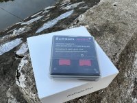
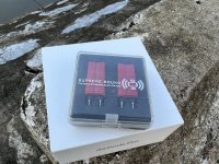
Now things have moved on since the original design with vastly improved discrete alternatives available from SparkoS Labs., Inc.
Parts and specifications listed below:
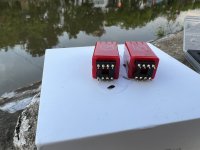
U1SparkoS Labs. SS79XX 796.8 custom -6.8v-6.8V3.5uV-125dB
U2SparkoS Labs. SS78XX 7815+15V6uV-125dB
U3SparkoS Labs. SS79XX 7915-15V6uV-125dB
U8SparkoS Labs. SS78XX 786.8 custom +6.8v+6.8V3.5uV-125dB

There are some differences in the way the two vendors conduct their measurements. Even taking that into consideration, the discrete parts offer significantly improved performance, also for load regulation.

I won't get into superlatives, but this offers a serious improvement and I'd always felt the INT-250 was capable of yanking a much higher level of performance out of a set of speakers. To me, music is about emotion and you can really feel it.

I've seen comparison elsewhere between high-end integrated (Diablo 300 The Gryphon) and the INT-250 where the defining difference was listed as low/mid bass, dynamics and micro-details.
I'd say these are exactly the areas that improved. It's no small improvement either and I'd recommend anyone that owns one of the Pass integrateds (likely also pre-amp's) and is so inclined to try the modification.

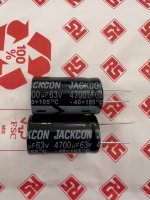
I think the step-up is due to a combination of pure regulator performance and also the increased reservoir from the integrated 10uF tantalum polymer output capacitor.

Note: I've listed the recommended SparkoS regulator parts. You can use (but it's not recommended) the SS7805 as a drop in replacement for the JRC 7805A (Pass use a red LED as a low noise method to increase the regulator output by its forward voltage); however it is not possible to use a SS7905 for the JRC 7905A -5v regulator.
Furthermore, the LED must be removed and the GND connection shorted to ground for the 796.8/786.8 discrete parts, no dramas for an enthusiast.
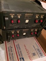
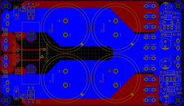
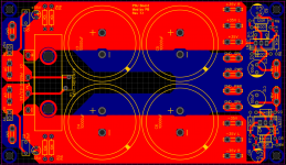
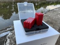
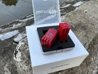
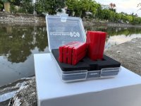
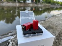
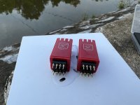
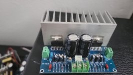
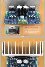
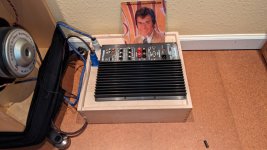
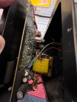
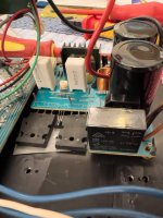
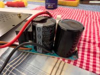
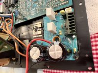
Some images:
U1 (I also added the heatsink for U1) & U3
U3 SparkoS 79xx N15V_04.jpg


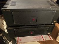
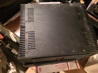
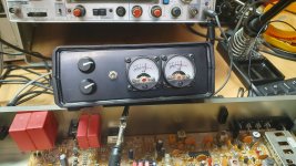
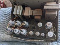
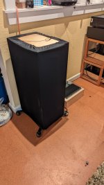
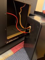
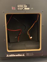
Next, dealing with the rather resonant steel top cover.
This was done with Monacor MDM-830 bituminous felt, it's around 4mm thick and perfect for the job:
Monacor MDM-830 bituminous felt_01.jpg


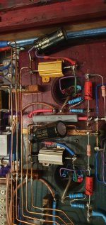
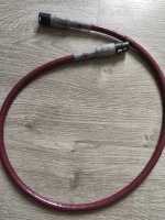
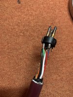
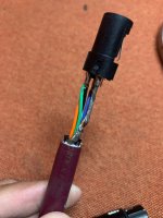
The other mod is more aesthetic, a bit of cable dressing:
front panel cable support_01.jpg

fabricated from 2mm dry carbon sheet
front panel cable support_04.jpg

  • Poll Poll
Bose SL2 Transmitter Sync cable pin out

What is a pin out for SL2 RCA connecting cable?

  • Audio connector

    Votes: 0 0.0%
  • RCA

    Votes: 0 0.0%

Hello Friends.

I lost a sync cable for the Bose Lifestyle SQL Transmitter wireless module. I enclosed a picture of a cable. It is an expensive to replace and trying to do it myself. I need your help if you could provide a pin out for this cable. Basically a 4 conductor audio jack map to RCA connector. Which conductor connecting to the RCA jack?

Link of a cable selling at Aliexpress

Thank in advance for your help.

International Differences

[Music] Many build systems for stats or authenticity, others, for purpose. It has occurred to me that Europeans have genres that Americans don't have. In Garage and Hardcore the bass is the lead. There was an era where club owners replaced drivers more often than light-bulbs. We are not talking about the odd church-organ note or movie explosion. We are talking about relentless abuse by kick and bass with no time to cool.

If you're from the US and hooked-up, tell me if your preferred genre offers more punishment than this . . .

Login to view embedded media

Taramps Smart 5

Hello, I’m stumped on this one. Replaced drivers, buffers, zeners and output fets and a few 4r7 resistors.

Inductors appear fine and output filter caps are in spec

Amp comes on and plays, has good drive waves with no dc offset, however, the output fets heat up quickly.

I suspect the drive frequency is too high? It’s 122khz. Anyone happen to have come across this issue and or know if this drive frequency is too high?

Question about compound woofers

Can we damp space between the 2 cones in a clamshell- type isobaric woofer?
We've already modelled and measured the response of two very similar(not identical) 12" woofers used face-to-face in a stuffed 1.5ft3 sealed box.
We initially have a box fc of around 40hz with a Qtc of about 0.8.
Would it be useful to put polyester stuffing/ wadding or maybe lightweight foam in the cavity between the woofers cones (or must it be empty)?
This might add a small increase in moving mass(7% to 10%), and maybe offer some damping of any cavity resonance that may exist in the space between the two cones(?)
(...or is this a solution in search of a problem?)
Any insights or experience related to these questions?
Thanks
-Chas

LM3886 power supply

First post contains the latest revision v7.1 of the board. Starting from the second post you can see the process and discussion on how the final version was created.

Relevant discussion on LTspice simulation, CRC PSU type, and general PSU design considerations can be found in this thread - https://www.diyaudio.com/community/threads/need-help-with-ltspice-psus-crc-filter-simulation.386838/

EDITED 11-9-2022

FIXED MAJOR MISTAKE IN THE LAYOUT!!!

Pinout of the LM337 in TO-220 package is not the same as with LM317!

Pin 1 is ADJ for both LM317 and LM337

Pin 2 is IN for LM337
Pin 3 is OUT for LM337

Pin 2 is OUT for LM317
Pin 3 is IN for LM317

Power supply board was assembled and tested and now comfortably sits in my amp delivering power to two paralleled LM3886 per channel and six opamps (LM4562 and TL052)

Power supply PCB:
  • Space for four 10,000 uF capacitors.
  • Space for +/- 15V regulators based on LM317 and LM337.
  • Regulators have a space for 0.1uF decoupling capacitors right next to them.
  • Space for bleeder resistors and/or LEDs.
  • Rectifier bridge used is Vishay PB3510-E3/45 rated at 35A and 1KV. PCB has a space for the rectifier heatsink.
  • Space for the snubber capacitors for each of the transformer coil.
  • Space for MOV that limits power on voltage spikes. MOV MOV-14D101KTR voltage rating is 60 VAC - that is 10V over the total voltage of the transformer second 25V+25V=50V.
Mouser part numbers:
Rectifier bridge - 625-PB3510-E3/45
Heatsink - 490-HSS08-B18-CP
Heatsink pressure clip - 490-HSC-06

Transformer used is Antek AS-4225 (400VA), but AS-3225 (300VA) or AS-2225 (200VA) can be used too.

Gerber files are attached. Great website to make those boards is JLCpcb.

Attachments

  • Gerber_PCB_psu-board-r7.1.zip
    Gerber_PCB_psu-board-r7.1.zip
    60.7 KB · Views: 143
  • pcb-b.PNG
    pcb-b.PNG
    112.4 KB · Views: 500
  • pcb-t.PNG
    pcb-t.PNG
    113.5 KB · Views: 485
  • sch.PNG
    sch.PNG
    37.3 KB · Views: 507
  • Like
Reactions: HRDSTL

Idea for hybrid open baffle/sealed sub

I used to have magnepans in my system and toyed for years with various open baffle subs. I had at one time thought about building my end game system around open baffle speakers and a hybrid open baffle sub based on an idea I hadn't run across anywhere before.

But plans changed some time ago, and for whatever reason I realized recently that I never did anything with that idea or shared it so others could experiment. So, here we go...

1. Construct a sealed dual opposed sub with matched front/rear drivers, a little atypical in dimensions for a sealed sub in that wide and tall but shallow front to back (like an OB baffle) is desired. Size net internal volume appropriate for the two subs as a sealed design. Optionally, probably ideally, the rear driver is mounted inverted so that both cones face forward, and box can be much shallower as the magnets are not abutting and the cone for rear driver gives additional clearance for front driver.

2. Each sub is driven by indepent amplification channel.

3. Place an all pass filter before amplification for one driver (ideally, adjustable), such that above filter Fc the two drivers are in phase electrically (and cones moving same direction if rear is mounted inverted as above), and below Fc the subs are 180 deg out of phase electrically (and moving in opposite directions). If rear driver isn't inverted physically, it's polarity should be.

The result should be, I think, an essentially open baffle sub >> Fc where drivers are in phase, and an essentially sealed sub <<Fc where drivers are out of phase, passing through a transition region around Fc that I think will be some varying cardioid shape.

Negatives are the additional sub and amp channel needed which will add no output in the OB range over a single sub and amp, and maybe suboptimal baffle shape due to some required depth based on driver dimensions. Benefits? For starters, additional output in sealed range from the doubled sub and more importantly from sealed vs dipole behavior below panel dipole frequency. Also, the transition region should be a smoothly varying cardioid instead of whatever superposition you get from pairing an OB sub with a sealed or ported sub handling lowest frequencies not co-located. And, making an all pass filter adjustable is easy, so it should be pretty easy to fine tune the end result around enclosure design, drivers chosen, room size, and most importantly measured in room response.

Thoughts? Was this sold by someone for several years but ceased because no one wanted it!? 😂

JBL PRX525 to passive conversion crossover help

Hi Guys, so I have a set of these powered JBL speakers- 2 15's and a horn I believe. The amp module, and specifically the "input module" has gone out and is NLA. My quick thought was just turn them into passives as we have plenty of power amps laying around. Can anybody help with a crossover design? What do I need to know about the drivers and cabs?

For Sale Burson V6 Vivid Dual

opamp Burson V6 Vivid Dual New unused condition, I bought it from a domestic agent, just peeled it off to see. price 120$ for 1 box of 2 burson v6 vivid dual. I have 3 boxes left
Prices do not include shipping and other related costs.
I live in Ho Chi Minh City, Vietnam
Thanks a lot
Hieumai

Attachments

  • IMG_0171.jpeg
    IMG_0171.jpeg
    693.7 KB · Views: 73
  • IMG_0170.jpeg
    IMG_0170.jpeg
    690.4 KB · Views: 68
  • IMG_0169.jpeg
    IMG_0169.jpeg
    650.2 KB · Views: 69
  • IMG_0166.jpeg
    IMG_0166.jpeg
    426.3 KB · Views: 75
  • IMG_0167.jpeg
    IMG_0167.jpeg
    651.8 KB · Views: 75
  • IMG_0168.jpeg
    IMG_0168.jpeg
    411.7 KB · Views: 66
  • IMG_0165.jpeg
    IMG_0165.jpeg
    487.5 KB · Views: 66
  • IMG_0164.jpeg
    IMG_0164.jpeg
    256.1 KB · Views: 69
  • IMG_0163.jpeg
    IMG_0163.jpeg
    644.7 KB · Views: 67
  • IMG_0162.jpeg
    IMG_0162.jpeg
    238.9 KB · Views: 81
  • IMG_0160.jpeg
    IMG_0160.jpeg
    319.6 KB · Views: 62
  • IMG_0161.jpeg
    IMG_0161.jpeg
    233.8 KB · Views: 74
  • IMG_0159.jpeg
    IMG_0159.jpeg
    302.5 KB · Views: 71

New Jersey Boat Anchor

A New Jersey Electronics (NJE) Regulated Power Supply Model S-400-R followed me home Saturday from the TRW swap meet. The bottom plate is missing, but all the tubes test good and there is nothing obvious like leaking caps or smoked resistors wrong. It does 0-300 volts at up to 300 milliamps. A prior owner did a nice job of rerouting all the connections to front panel sockets. I'd like to find a schematic and or a manual for it so I can dial it in and start using it. Any leads would be greatly appreciated.

Listening,

John

Attachments

  • NJE ps front.jpg
    NJE ps front.jpg
    275.4 KB · Views: 100
  • NJE ps top.jpg
    NJE ps top.jpg
    265.3 KB · Views: 97
  • Like
Reactions: geraldfryjr

Crazy Turntable project

So, I'll admit, the following project is a bit crazy and will probably get some shaking of heads and "dude this guy is crazy" comments... but what the hell I'll share it with you guys anyway.

The project started with a perfectly working Denon dp1800.
20230101_182853.jpg


I always found it be a bit ugly so I decided to make him a new plinth and isolate the base of the tone arm from the motor vibration

20230425_170451.jpg
20230428_173853.jpg
20230430_080754.jpg


The new plinth is made out of mdf that I submerged in white resin making a 1cm thick skin. The black layer sandwiches between and below the white layers are HPL (a tough resilient material-a bit like what Wilson Audio claim to use in their loudspeakers).
The tone arm construction is sitting on the 7kilo metal cylinder and not touching the plinth.
It is bolted to the base layer (hpl-mdf-hpl) which on top is a layer of memory foam which on top sits the plinth. I have later discarded the memory foam in favor of Isoacoustics Pucks (better).


Now for the crazy part 😜
I have decided that all of this is not enough and such a construction needs a good base.
So... here is the construction of an earthquake proven base (took me 2 weeks to think about- your welcome 😀)
20230623_151529.jpg

20230623_154303.jpg
20230623_181437.jpg
20230624_152159.jpg
20230624_153826.jpg

safe to buy old multimeters?

hello all,

I saw a Klein MM700 on ebay for $60 USD. The meter is at least 4 years old(the seller also bought it used). Is this a safe purchase? i am looking to "buy it for life" type of situation if it can apply. it costs under $30 to replace the 2 fuses too(unsure if that should be done too)

Would be using this multimeter to build amps from DIYaudio and fix house things.

it looks like the MM700 has more features and is lower cost than a fluke 107. I couldnt find a used 107 thats cheaper.

open to any suggestions as well!


thank you
Peter

Ports 'Going Turbo'

I was watching an old video from Erin's Audio Corner and noticed on the compression testing at high levels the port tuning frequency actually gets louder than the baseline. In addition the tuning frequency moves upwards. This caught be off-guard and I thought it was super interesting! Just look at 102dB, well above the 76dB baseline at 85Hz!

Philharmonic%20BMR%20Monitor%20v2_Compression[1].png


I'd expect the port to increase efficiency and therefore reduce compression, but did not expect it to put out more than the amplifier gain!

I wondered if this is a known or studied phenomenon?

My guesstimate would be it's to do with air velocity being high enough to break down the boundary layer friction at the port walls, much like the way a golf ball can travel further when the boundary layer air is separated by adding dimples.

Encouraging this behaviour (B&W!) to gain higher efficiency seems like a good thing, but I'm not sure it is - this says nothing for how pure the sound is nor how linear the gain is at different levels. Still, if this additional efficiency could be had at all operational levels it might be very beneficial in PA systems.
  • Like
Reactions: stv

For Sale KYYSLB E360 Beautiful 2U Amplifier Similar to Krell or Levinson

Well, I am very sad to be giving this enclosure up. I had great plans for this beautiful enclosure to house 4x500 Hypex NCores on a pair of Selah line arrays, but life has taken a different direction so it is now for sale. I never even took it out of the box, and it is still disassembled and ready for its big debut. New + very long sea freight from China to the USA these are ~$355, currently on sale for $296. I waited almost 90 days for mine during peak Covid in 2021.

I am asking only $197 shipped in the USA. That is 1/3 less than current retail pricing, plus the buyer will receive it in under a week vs. 45-90 days. Please message me if you are outside of the USA and I will be happy to send you a shipping quote.

1000003804.jpg

1000003803.jpg
1000003802.jpg

KT88SE -burnt cathode resistor

Hi all,

Hoping someone can provide some advice.

For 2yrs my KT88SE amp has been running for around 12hrs a day with no problems.

Today, a distinct burning smell for the first time and having removed the bottom plate, one of the cathode resistors had all the gold colouring removed, and was extremely hot to the touch. (See photo, left hand side). After about half an hour, still extremely hot to the touch. I wanted to mount these on heatsinks but I was a month or two away from doing this.

The amp, other than smelling, was still sounding great, I was baking a loaf of bread (lol) and thought it was that so, after an hour of smelling burning, I realised it wasn't the bread but the amp!

Ambient temp is hot at the moment but would anyone know why this has happened, only on one channel, the other seams fine.

Circuit is the Abdella Blue Glow version of the KT88SE, cathode resistor is 500ohm (10w in circuit, 25w in my amp) parrelled with a black gate, which is quite old now and has been subject to high heat.

Thanks in advance.

Attachments

  • 20230626_220629.jpg
    20230626_220629.jpg
    381 KB · Views: 164

Soundstream Rubicon 502

New to the forum, I discovered it trying to figure out what’s wrong with my rubicon 502. I’ve been using it for years and something just went on it I think. I’m not the best at repairs? I’m pretty good with a soldering iron but don’t have an oscilloscope or anything but figured maybe I could bring her back to life.

My best guess is it’s overheating and going into protection mode. Sometimes when I turn it on clip lights will light along with the power led but it will then shut itself off. Checked all my fuses and unplugged the negative from the speaker but no love. When it first happened it was really hot to the touch. I have not cracked it open yet but I’m guessing something went.. no smoke that I saw or burning smell.

I read some previous forums on diodes and caps failing but I’m not sure how to test.

Thanks in advance for anyone that can help

Cartridge measurement - fluctuating signal

I am having difficulties in receiving accurate measurement signals from the cartridge.
Picoscope is set to AC, which does not make any difference. Also digital filter setting does not improve the situation.

Are there any ideas, how to remove low frequency rumble and wrap from the signal? (wihtout an active subsonic filter)

Many thanks for any ideas.

Michael

How about a Sasandu "TXB"? Swap in the Satori Beryllium Tweeter for the TeXtreme tweeter...

The Sasandu TX kit fascinates me, because at least in North America, there is One Stop Shopping!

Solen in Montréal has the drivers and the finished cabinets and all the other parts, and can assemble and test the crossovers, and ship completely assembled speakers!

Solen can also build a crossover with "Boutique" capacitors and coils.

I am dispositionally incapable of Leaving Well Enough Alone. So, looking at the FR graph of the TeXtreme tweeter, there seems to be a "whiplash" dip and peak from 20kHz:

Satori TeXtreme tweeter.png


Now, the Beryll tweeter is not ruler-flat up there, but, it might be more benign:

Satori Beryll tweeter.png


So, my gut feeling, especially in view of all the praise the Satori Beryllium tweeter has had showered upon it, is that for a US price increment of say $300 on the pair of speakers, swapping out the TeXtreme tweeter and swapping in the Beryllium tweeter might make sense.

Now, Customs and Shipping will complicate the picture, but, my guess is, that for a lot of the US (in terms of shipping to the Heartland), they could get an assembled tested pair of Sasandu "TXB"s for under $7500. But from the looks of things, anything below $10,000 would be a bargain, compared to imported loudspeakers sold in audio salons via Triple Tier Distribution.

Hard to beat with a stick, I say!

What think ye Bests and Brightests?

all my best,

john

Question - How to choose weight of replacement anti-skating weight?

I have a couple of tonearms that are missing their anti-skating bias weights. One is an Audio Technica AT-1005mk2, the other is an Audio Technica AT-1501mk3.

According to one forum post, the AT1005mk2 came with two weights, one 2.2g the second 1.7g. I guess those were designed to be used singly or both together for extremely heavy cartridge/headshell combinations. If I'm using a headshell weighing in at about 12g, and a DL103 weighing about 8g (20g total), with tracking force of 2.5g, would I want to choose a bias weight of 2.5g? Or do I want a heavier counterweight (e.g., 4g) so I have some room for adjustment/tweaking? Or is the calculation of the weight more complicated than that?

Also, is fishing line acceptable for stringing up the anti-skate bias weight? My AT-1501mk3 came with its weight strung with thin metal string, which I unfortunately snapped. Is the stretchiness of fishing line a liability? Or is that a non-issue?

This is the first time I've tackled this kind of project, so I'm a newbie. Any advice would be much appreciated.

Tube Curve Tracer for Sale

Based on the uTracer3+ kit. I built several of these for a project that is not going into production. These were intended for use at the factory for testing and sorting of various tubes.

Since I don’t need more than one curve tracer in my life, I have 3 of these for sale.

About the curve tracer:

  • Based on Roland Dekker’s uTracer3+ board. There is a lot of info about this board at www.dos4ever.com/uTracer3/uTracer3_page0.html. This is a very nicely designed kit that implements a full-featured curve tracer.
  • The finished unit has a rugged USB connector, AC mains IEC connector and switch, internal power supply (19V laptop supply), USB to RS-232 adapter (Prolific chip set), front panel status LEDs, and keyed banana jack connections. The processor has been replaced with a Black Magic Amps version that adds a huge number of improvements (see below). Everything is packaged in a Pelican-type case made by Seahorse, with a professionally made front panel, as shown in the pics.
  • Since this was intended for factory floor use, I designed plug-in adapters that mate with the banana jacks on the unit. Each adapter is wired for a specific tube type, so there is no chance of setting switches or jumpers incorrectly. I include one adapter pre-wired for the 12A*7 family of dual triodes, along with another 9-pin adapter and two 8-pin Octal adapters. These adapters are not wired internally yet. You can configure these for your favourite tubes using short jumper wires.
  • Since some users will also want to test various other tubes, I designed a “universal” adapter, one of which is included. This has 9-pin, octal, and 4-pin (see note below) sockets that will support testing of a wide range of tubes. Use short banana jumper cables (not included) to connect to the main unit.
  • The adapters are housed in 3D printed cases. I can provide STL files for these if you want to print your own. I can also provide Gerber files for the adapter boards if you want to make more (for your own use, please.)
  • A few specs:
* Anode and Screen voltage: 400V Max @ 200ma
* Grid voltage: 0 to -50V
* Heater: 0 to 19V @ 1.5A
* Approximate size: 11in x 10in x 5in
  • The Black Magic Amps (https://bmamps.com/v01/home/techie-corner/utracer-utmax/) processor supports better anode, grid, and heater voltage setting accuracy, firmware updates over USB (unit is shipped with the latest version, 3.06), much faster tests, and overall more stable operation. The original processor is included if you want to switch back for any reason.
  • The unit comes pre-calibrated and ready to go.
  • Note that the grid voltage is -50V max. While the universal adapter has a socket that will work with tubes such as the 300B, this may not be enough grid voltage for your particular tests. In that case, there is a mod you can make to the uTracer board to increase the grid range to -100V. There is information on both the dos4ever and bmamps sites on how to do this.
  • Other mods: I’ve made a mod to the grid supply circuit to improve performance at low voltages. Unmodified uTracer3+ boards have trouble with grid voltages below about 0.5V, but with this mod they work fine to below 0.1V. I have not made any other mods to these units.
  • Other mods you can do: as mentioned, there is a -100V grid voltage mod. There are also a wide range of mods that are documented on both the dos4ever and bmamps sites, including ones that provide faster testing times, higher anode currents, a grid offset mod that allows accurate grid voltage down to 0V, and more.
  • Software: the dos4ever site has a Windows application that works well and has many useful features. You can download it for free from the Downloads menu at https://www.dos4ever.com/uTracer3/uTracer3_pag0.html. The bmamps site has an excellent application that runs on Windows and Linux, and has many improvements, including faster testing, easier calibration, a very nice GUI with interactive graphs, spice model output based on measured data, and so on. You can download it for free from https://bmamps.com/v01/home/techie-corner/utracer-utmax/. As a bonus, this app is also open source, so you can add features of your own.
  • NOTE: I am in no way affiliated with Ronald Dekker, Dos4Ever.com, Black Magic Amps, or Nick Barton (owner of BMAmps). I have simply used their products to make these curve tracers. Hats off to both Ronald and Nick for the excellent work they’ve done and put out there for us all to use.

Included with each Curve Tracer:

1 assembled, tested, and calibrated curve tracer in Seahorse case
1 pre-wired 12A_7 adapter
1 unwired 9-pin adapter
2 unwired octal adapters
1 assembled “Universal” adapter for 9-pin, octal, and 4-pin (300B type) tubes

USB cable and AC power cable not included.

Cost: $1500 USD, plus shipping from Australia

IMG_3187.jpg


IMG_3191.jpg
IMG_3183.jpg
IMG_3192.jpg
IMG_3190.jpg

HV Pulse amplifier help 6BK4

If this is the wrong place, tell where I should post.
I'm building a HV pulse circuit for a specialized electrophoresis.
High Voltage, Low current, under 1ma.
I plan on using a 6BK4.
Here are the tube specs,
https://tubedata.tubes.se/sheets/127/6/6BK4.pdf

I have been given a schematic that I'm sure is a little unconventional,
but have respect for the designer, although he said, "it may need tweaking".
The design ties the grid at +6v and then pulls the cathode to 0V, to pinch it off.
I love the simplicity of the circuit, but will it work. Note: expecting to pulse 7kV or more!
I'll post the design and I asking for input about whether it is a viable design,
or what would you change. See attached file or dropbox picture.
https://www.dropbox.com/s/cxv0osk0z3yc7fo/Oil Water, Pulser Schematic.jpg?dl=0

Thanks, Qmavam11

Attachments

  • Oil Water John's Pulser Schematic.jpg
    Oil Water John's Pulser Schematic.jpg
    375.2 KB · Views: 258

Autobias install questions

Hi all,

I'm going to install the AB-Qi modules in my homebrew monoblocks and have some ideas/questions I want to discuss. They are currently cathode biased.

First off my design uses only 2 coupling capacitors but has 4 output tubes. I'm intending to bias the tubes as pairs ala Audio Research because I'm loath to add another pair of caps into the signal path to individually bias the tubes.

The AB modules run the cathode resistors on the board and have you remove all connections. Ok fine, but in my case with 2 tubes biased together I want to have the cathodes tied to ground with 1R resistors, giving me an easy test point for current for the 2nd tube which will NOT be connected to the AB module.

If I'm visualizing the circuit correctly having 1R to ground won't affect the voltage feedback to the AB module.

So two questions result: am I ok to have the 1R cathode resistors in place with the AB module? And should I just bite the bullet and add more coupling caps to bias individually? It sounds so lovely as it is that I am really hesistant to mess with the signal path.

Vintage Acoustic 807 PA loudspeaker cabinet rehab

I picked up a pair of vintage three-way Acoustic 807 cabs for keyboard use. Each cab is rated at 8 ohms and contains two ceramic-magnet 12"s (one is ported in the cabinet, the other is closed off), one 4"x10" mid horn, and two piezo tweeters. The two 12"s and the two piezos are paralleled. As measured by a DMM, the two 12"s and the mid horn are 16-ohm (they aren't marked). The guy I bought them off of told me one of the "tweeters" had been replaced but on inspection it's the mid horn, and it was replaced with a Gem Sound unit that's 8-ohm.


Here is a simplified schematic of the crossover. I have not drawn in the circuit breaker or the shunt resistor that's in parallel with it; if I had, it'd be in series with the capacitor, to its left.

index.php
One problem is that the replacement 8-ohm horn seems to have the effect of nearly shorting out the tweeters; they're speaking but just barely when I feed the cab white noise.


I started going over these cabs with the idea of bringing them to spec as their designers intended, which is complicated by the replacement horn being the wrong impedance. But in the crash course I've been giving myself on crossovers (EE degree but I specialized in digital; practical application of passive crossovers was out-of-school education only), nowhere have I seen discussed the idea of just throwing a low driver across the input and letting its highs be diverted parasitically like this.


The original mid horns and the 12"s appear to be Panasonic/Matsushita; I have tried and failed to get any specs based on what little info the stamped codes provide.


I know there is no one "right" answer for what to do here, but I would like to make these cabs serviceable for keyboards (analog synths and VST instruments). I have even thought about circumventing the original crossovers entirely and just bi-or tri-amping these things; I do have a second power amp that I could press into service and I can spare 1U of space in the rack case for an active crossover. But if I biamp (versus triamp) I still have to work up some sort of passive crossover between the mid horns and the tweeters; it's not clear to me that doing that is better than sticking with one power amp and giving the cabs new 3-way crossovers, perhaps along the lines of this.


Anyway, what do you think?

Tik Tok Pranks

This is a thing now I guess. Since I live on the corner I have been subject to a few apparently.

The first one was when someone was kicking my door like they were trying to break in. It was early evening and it was clear that I was home; the windows were open and the music was playing loud. I was very unnerved and called the police. They arrived virtually instantly but the prankster had already fled in a vehicle. The police said it was a Tik Tok prank.

The second prank was when they threw an orange power all over my yard and gardens. I did not know what this powder was but I thought the worst. The police did not come for that call but the dispatcher said that it was a Tik Tok prank.

Last night around 2 AM I heard commotion in the back yard. I could hear someone in my back and side yards and a vehicle was idling by the side of my house. They fled when I turned the lights on in the house. I do have motion detector lights in the back yard, driveway, and facing the alley, but this is evidently not a deterrent. When the police arrived, there were three suitcases on my property; one in the front yard, one in the side yard right underneath my bedroom window, and one in the back yard. The police took a while to arrive but when they did they arrived in multiple vehicles. They found the suitcases and carefully opened them. All three were empty. The police said once again that this is a Tik Tok prank.

I don't know the purpose of these pranks, but my prediction is that one day these pranksters are going to get Tic Toc'ed with a Glock. Playing around on someone's private property is just inviting a beat down.

QUAD ESL 63 neon bulb flashes only once when plugged in

Hey,

Last week I traded a pair of my ESL 57s with someone for a pair of ESL 63s. It made him happy. Unfortunately the 63s appear to be malfunctioning.
One ESL 63 plays even softer than the other especially compared to my 988's. I gather they should play equally loud?

Following Sheldon's advice in an older thread, I unsoldered the T2800B from the clampboard, but that didn't work out.
That's why I now suspect that the EHT unit is not building enough voltage. Thanks to Sheldon, I learned that bad diodes often turn out to be the cause.
I replaced all 8 of them with new GP0230E3 diodes, but without any result.
Before I proceed to the next step; replacing the capacitors on the EHTs, I would like to consult you first.

- What I find remarkable is that the neon lights that should light up with a certain regularity, remain off. They only light up once; when the ESLs are turned on.
-The ESLs don't make any disturbing noises.
Any ideas?
Thanks for reading this.

Kenwood C2 transformer replacement

I have a Kenwood C2 preamp that isnt outputting any energy from the four small wires (white, yellow, black, red) of transformer to power supply circuit. Jumping the switch did nothing. Part number is L01-2776-05 Nothing found on ebay. Is there a toroidal or another center-tap transformer that could be accommodated? There is plenty of space for a toroidal.
kenwood c2.jpg
.

Technics SL-D2 platter is spinning too fast. Help

Hello, I recently acquired my brother's Technics SL-D2 Direct Drive Turntable. Upon powering up the unit, the platter is spinning too fast (any record sounds like Alvan & the Chipmonks). The moving the 33 / 45 switch as no effect & strobe Sync light is on and is steady. The pitch control knob has no effect on slowing down the platter. I've have used contact cleaner on the switch and pitch control to clean the contacts, with no impact. Any ideas?

Safety precautions when working with Toroidal transformer connected to mains

Hi,
I want to work a DIY network streamer including its power supply. The power supply consists of 2 toroidal transformers (1) 12 V output (2) 6 V output. I'm in US, so the input voltage will be 110-117V. I have been able to understand all the connections from the transformer output to the digital audio output.
One place however I am not getting much headway is how to safely connect the transformers to the AC Mains so that (1) I minimize the chances of any shocks during development phase (2) How to handle grounding from AC Mains (3) What is the right and safe way to measure voltage across the outputs of the transformer when connected to AC mains (4) Where to use a fuse if the AC mains has a surge?

Any help would be really appreciated.

How bad input voltage offset difference between the two LM3886 will be in the schematics below?

From https://neurochrome.com/pages/output-power#parallelBridgeBoth:

"Do note that when connecting two LM3886es in parallel, ballast resistors must be used to ensure that the two LM3886es share the load current evenly. Also note that the input voltage offset difference between the two LM3886es causes a standing current to flow through the ballast resistors. This standing current must be minimized to avoid excessive THD even at moderate output power levels. To accomplish this, the input offset of each LM3886 must be minimized, preferably using a DC servo thereby increasing the complexity of the circuit considerably."

I therefore wonder how bad will the standing current will be in the below schematics? Is servo absolutely necessary or I can do without?

Help much appreciated!

sch.PNG

Mini PC windows components list

HI,

After my first DIY streamer I'm looking for new components to build my new x86 based version for windows system.


I already have 3 touch displays 7", 8.8" and 12.6" tested under Windows 11 and they work fine. I also already have 2 audio power supplies, linear and low noise (the first 12V 120w, the second 5V 50w)

In my project I'd like insert, inside the new case (WIP), the SMSL D0300 DAC (already tested with excellent results) and the power supply. All connection ports will be replicated on a rear panel of the case. Also I already have a mini PC Intel Celeron 5105 8Gb Ram and 256Gb of storage space. Unfortunately this mini pc has a small fan inside and it works fine because it has that fan. From my personal research on the web, all high-performance fanless mini PCs have problems because when the temperature rises it causes system freezes or slowdowns, in particular the wifi module blocking.

Is there a tested list of components that we can use inside our case? It must be considered that including the internal power supply, the touch display and the DAC, these give a great contribution to the heat growth and this is a big problem for the most performing fanless CPUs...

What choices would you make for the mini PC components? Whereas all the parts included in the case (HIFI FORMAT) will be stripped of their individual boxes/cases

Thanks

people gripe about bad service, but what about tube companies that go beyond?

I recently ordered a pair of "Black plate JAN Raytheon 5842WA" tubes from thetubestore (Canada) to me in the USA.

They were supposed to be delivered to me on last Monday June 19, and the status at UPS showed out for delivery.
1687827863847.png

However they never arrived. Then on Tuesday UPS tracking showed a cryptic message that implied the package was in my town and out for delivery. On Wednesday it showed it was not in my town, but at a distribution center. The UPS web site bot couldn't resolve it so I texted thetubestore and got a reply from Hydn that they would look into it.

I eventually took the tracking number to my local UPS store and they advised me that due to a UPS screw up they seemed to be held up in Louisville KY customs. This was Thursday.

Mid day Friday I got a email from Haydn stating they would send me a replacement package.

I emailed back they could wait until Monday to see if UPS resolved it.

They went ahead and sent the replacement package any way.

I received both packages Monday in the same delivery and informed (thetubestore) then.

They sent me a return shipper and associated paper work for the return of the second package,which I dropped off at a UPS store today (Monday).

This is exceptional service from a company which stands behind their customers and provides a great level of support. I highly recommend them.
  • Like
Reactions: rayma

About BEOLIT15 Restoration and APP. Issues

Hello Everybody 🙂
I would greatly appreciate any thoughts/guidelines/know how with regards to the issue herein:
So, I received a BEOLIT15 BT speaker that broke down.
Being such an expensive speaker, I decided to try and fix it.
The BEOLIT15 incorporates a BT module (BTM865a) with a CSR8670 chip, which is also used as the speaker's host.
As it turns out, the module suffered some kind of damage and did not power up at all. Any attempt to access the module using CSR's PSTool or BlueFlash failed.

Since there was no other choice, I reached out to a seller of mine and he helped me obtain used BT modules identical to the one that broke down.
I then removed the inoperative BT module, installed the replacement and used a dump image to reprogram the module. I changed the BT address and managed to connect to PC/smartphone

Nevertheless, the speaker currently has a problem:
Since the dump file used has been extracted from a similar device operating from the same smartphone, the BEOPLAY app is unable to register and operate both speakers. There is most probably an additional key besides the BT_ADDR that has to be changed, but I have no idea what it is

I did ask B&O for some help...but was not surprised when there was no answer 🙁

If you stumbled across a similar scenario and may know which PSKey could solve this issue thereby allowing the BT to be registered correctly by the app. please be so kind to drop me a reply (Please note that regardless of the app - the speaker does connect to the phone's Bluetooth and plays music)

I will add the PSKey dump to the thread
Thank you so much for your time and apologies for the lengthy letter
/Indium

Attachments

Headphone amp for HD 560 120ohm

Headphone amp for Sennheiser HD 560S (120 ohm) using readily available and cheap Toroidal transformers for power supply. A 50VA 55 + 55 volt with series connection for 110volts is sufficient and the filaments can be driven from an 80VA toroidal with 12Volts via LM317 regulators. The distortion (Simulated but not measured) is of the order of 0.04% at 10khz and mainly second at 1 Volt out. Power supply noise is un-auditable. The amp will run into 60 ohms ok but the distortion goes up a little. Sounds excellent.

Attachments

  • SchAmp.pdf
    SchAmp.pdf
    51 KB · Views: 150
  • SchPS.pdf
    SchPS.pdf
    121 KB · Views: 83
  • DSC04109.JPG
    DSC04109.JPG
    280.3 KB · Views: 101
  • DSC04111.JPG
    DSC04111.JPG
    274.1 KB · Views: 107
  • Like
Reactions: Stanislav

Fostex FF85WK mini speaker (Double Bass-Reflex type, W.110mm, H.220mm, D.150mm)

I built a mini speaker using FOSTEX's best full range FF85WK ever.
Although it is small, it ensures the minimum necessary bass, and can be used for almighty with natural mid and high range.

The enclosure is made of 9mm thick MDF wood, and the finishing is done with vinyl sheets.
The total material cost for the enclosure amounts to $11.

HB-07F-ML+FF85WK-05.jpg

Attachments

  • HB-07F-ML+FF85WK-06.jpg
    HB-07F-ML+FF85WK-06.jpg
    184.7 KB · Views: 395
  • HB-07F-ML-01.jpg
    HB-07F-ML-01.jpg
    185.7 KB · Views: 429
  • HB-07F-ML+FF85WK-01.jpg
    HB-07F-ML+FF85WK-01.jpg
    106.1 KB · Views: 428
  • HB-07F-ML+FF85WK-02.jpg
    HB-07F-ML+FF85WK-02.jpg
    54.3 KB · Views: 327

Filter caps in "Hohner Orgaphon 61 super reverb"

I´m recapping an old organ amp. It sounds awesome...
Unfortunately it uses extremely rare tubes....But ill look into that later 😉

There are 5 big electrolytics

two 100uf+100uf
three 50uf +50 uf

so the dual type filter caps

It is a bit confusing to me, that these dual caps only have two solderlugs?
Usually, dual capacitors have 3, right?

Kind regards, Kasper

Connecting TDA7293 in parallel

I bought this "xh-m210" tda7293 board from aliexpress tried connecting it in parallel, sound gets distorted and start to get hot really fast.
1. How can I connect it in parallel?
2. How can you make this board better/ sound better?

Attachments

  • IMG-20230609-WA0010.jpeg
    IMG-20230609-WA0010.jpeg
    224.4 KB · Views: 167
  • HTB1nd8TOVXXXXbsapXXq6xXFXXXb.jpg
    HTB1nd8TOVXXXXbsapXXq6xXFXXXb.jpg
    289.1 KB · Views: 172
  • XH-M210-TDA7293-AC-12-32V-dual-channel-100W-100W-2-0-super-power-amplifier-board.jpg
    XH-M210-TDA7293-AC-12-32V-dual-channel-100W-100W-2-0-super-power-amplifier-board.jpg
    77 KB · Views: 170

What the heck is "hybrid SACD"???

What is the downside to a "hybrid" SACD? I don't do SACD and never will, only CD.

It seems that somehow the laser on an ordinary CD player like mine somehow shines through the SACD layer and hits the deeper CD layer instead. How is it possible that there isn't going to be some sort of degredation as the CD player's laser shines through something that isn't completely transparent?

Are both layers made with dyes or is the CD layer made with old-fashioned CD pits and lands and deposited aluminum? I have had poor experience with CDs made with dyes over the years. They degrade and have inferior sound quality in my opinion. Your mileage may vary.

Music Angel KT88

Hi, have a music angle with 4 KT88 tubes. But when i turned it on an evening, one tube flashed and i turned it off.I opened the amp but realised quickly that this is a complete new world for me, this is my first tube amp.but i did not see any burned parts. so my question is, do i rip all the internal out and buid a complete new amp or is it worth trying to find the fault that destroyed my tube? i have understand that there is many versions of the music angel. i have not found any pics on google thas looks like mine. And i also want to remove the preamp section on the amp. i want is as a clean power amp. But can i turn the amp on without the tubes and meassure the different voltages on the channels? to see the different voltages, if thats was the issue that killed my tube, if it is killed. i dont know tubes that well. can a tube survive something like the problem i describe? can i meassure the tubes with a multimeter to check if its ok?

10Y (or other DHT) replacing a C3G driver

Hi, thanks to many of you who helped me design and build my C3G drives 45B monoblocks. I really enjoy them and most surprisingly, I rarely drive them into overload using my 90db efficient speakers (Ilumnia Magisters). The Magisters really excel with the DHT amps. So smooth and natural.

The attached schematic is of the existing monoblocks. I am considering replacing the C3G with a DHT, such as the 10Y. If you have any experience with both the C3G and the 10Y as driver tubes, please share you opinion on the sonic differences. I am curious to learn what sonic changes would accompany the 10Y driver. I am open to DHT alternatives to the 10Y.

Any input would be appreciated.

Pat

Attachments

  • C3g-45B v11 copy 2.png
    C3g-45B v11 copy 2.png
    77 KB · Views: 1,320

ISO audiophile blues and jazz on CD

Hi all, I am having a hard time finding high quality recordings of jazz and blues that I like on CD. I love the great artists like B.B. King, Albert King, and John Lee Hooker. Also looking for any other recommendations based on my likes and notes listed below:
  • Even though it isn't what some would consider an ideal recording environment, I find that the recordings of John Lee Hooker and Albert King on the CD "I'll Play the Blues for You" (Tomato Records) are pretty good in that they do give a "you are there" experience inside a small club with live music. I like that very much.
  • B.B. King's "Live at the Apollo" CD has been a favorite of mine for a while. I do prefer live recordings when possible.
  • Jazz at the Pawnshop is another favorite CD.
  • The Leon Thomas Blues Band CD that I bought in the 1990's is a good recording, and I like the music. I wish they had recorded it live.
  • Even though they are very early and somewhat harsh all-digital recordings, I like Tunnel and Big Notes by Flim and the BB's. I wish they had been recorded on analog equipment instead of very early digital, but back then (early 1980's) all-digital was sold and hyped as the best thing since sliced bread. It wasn't, as demonstrated by so many of the CDs of that era.
  • I own all of the CDs from Sheffield Labs except the ones that are classical music. Although much of their music is oddball stuff, they always did a decent job of recording I thought.
Any and all recommendations welcome. I'm having a hard time finding new music CDs to listen to on my recently upgraded system. I am looking for CD only, no streaming or vinyl at this point. I miss the days (1980's) when I could walk into high-end audio shops and almost immediately find new CDs that I liked as they played them on demo systems. One by one, every such store anywhere near me has closed over the decades.

Cantilevered feet, stability and steering

The speakers I am working on are tall and skinny.
I need some extra stability for just in case reasons. Where on earth can I get a set of decent short extension legs to add the needed stability to a tall tower?
Being able to adjust the rear height to tilt the towers would be a nice added extra/bonus.
I'm in Oz so local would be great due to the hindrance of International shopping at the moment

Hello from Canada eh

Hi everyone,
I've been a pro audio bench tech for about 20 years now and I play in an R&B/blues band as well. Looking forward to posting and chatting!

“The music business is a cruel and shallow money trench, a long plastic hallway where thieves and pimps run free, and good men die like dogs. There's also a negative side.”
― Hunter S. Thompson
  • Like
Reactions: Carlp and rsavas

  • Locked
TDA1541 DAC for sale

Sale of this item is withdrawn


This is a I2S to simultaneous mode TDA1541 dac board designed by Miro. Your own PSU and i2s source is required to complete this DAC for it to sing.

The 14 decoupling caps for the TDA1541 chip are high quality RIFA MKP, with values as per Miro's recommended BOM. Decoupling caps for the psu are KEMET MKP, and electrolytics are mainly Nichicon FG for the DAC section and ELNA Cerafine for the op amp IV. Resistors used are good low noise, metal films from Nikohm, vishal and Dale. Logic chips are decoupled with high quality Kemet SMD x7r capacitors.

The DC protection board is also included in this sale.

This dac is designed by Miro and more info can be found here :
https://www.diyaudio.com/community/...s-input-nos-r-2r.354078/page-268#post-7159210

Miro also designed the PSU for this dac (not included in this sale):
https://www.diyaudio.com/community/...s-input-nos-r-2r.354078/page-268#post-7159234
Please study the power supply requirement carefully if you intend to use your own psu design.

Important things to note :
1. If you intend to have no capacitor at the output, it is advisable to have a dc protection board (included in this sale) as explained in the post:
https://www.diyaudio.com/community/...s-input-nos-r-2r.354078/page-285#post-7187720
2. i have trimmed the TDA1541 offsets to be null and very stable. Any changes to the board, including inserting different op amp and different TDA1541 chip will require adjustments again. Please do check and do necessary adjustments by following the instructions by Miro. You will need to explore this on your own, with your i2s source connected.
3. All components, including the TDA1541A chip are new, which is only used for the testing of this DAC. The exception is the pair of output op amp OPA604 which are old and used by me for previous projects.

Of course, the board has been tested and playing well. Price for the board is 250USD, including shipping worldwide registered. And as usual i will buy coffee for Miro.

New Hifonics BRX2400.1D in protect

Hi everyone!

About 6 or 7 years ago I bought 2 Brutus 2400.1D amplifiers for a project but only one of them was ever used, however due to an unlucky water leak in the car it shorted out and burned out several transistors. However while repairing it I decided to dust off the other amp, said and done I installed it in the car but when I fired the stereo up I got a loud thump from the sub after about 4-5 seconds (no music) and when I went to the trunk I found my dear sub locked in the bottom and the amp was in protect. Removed the amp from the car again and tried firing it up with only power wires and it fires up fine but the relays click back to off immediately after clicking on and amp goes into protect.

I have opened it up and am unable to find anything wrong with any power/output transistors, there is no apparent visual damage and it smells new still. I'm quite unsure where to start looking right now, any suggestions where to start?

Fixed my humming KEF 30B subwoofer.

After doing some research, it sounded like the first place (after checking ground cable) was to replace the two output capacitors. These are aluminium electrolytic capacitors. I managed to find identical capacitors from RS.

When dismantling the amplifier in the subwoofer, I found the transistors were stuck to the chassis. Left some WD40 to soak over night and they came off.

Fortunately the capacitors were not overly glued, so they weren’t too bad to remove.

Happy to say this fixed the hum, and they now sound great again.

Attachments

  • IMG_5901.jpeg
    IMG_5901.jpeg
    310.7 KB · Views: 375
  • IMG_5902.jpeg
    IMG_5902.jpeg
    288.9 KB · Views: 438
  • IMG_5903.jpeg
    IMG_5903.jpeg
    245.4 KB · Views: 293
  • IMG_5908.jpeg
    IMG_5908.jpeg
    255.4 KB · Views: 566
  • IMG_5911.jpeg
    IMG_5911.jpeg
    370.8 KB · Views: 445
  • IMG_5951.jpeg
    IMG_5951.jpeg
    348.8 KB · Views: 324
  • IMG_6007.jpeg
    IMG_6007.jpeg
    406.4 KB · Views: 343
  • IMG_6067.jpeg
    IMG_6067.jpeg
    479.5 KB · Views: 340
  • IMG_6111.jpeg
    IMG_6111.jpeg
    476.5 KB · Views: 321
  • IMG_6115.jpeg
    IMG_6115.jpeg
    364.8 KB · Views: 326
Projects by fanatics, for fanatics
Get answers and advice for everyone wanting to learn the art of audio.
Join the Community
507,718
Members
7,885,677
Messages

Filter

Forum Statistics

Threads
406,114
Messages
7,885,677
Members
507,718
Latest member
Brano KAntor