Dayton Audio DATS V3

Good evening everyone

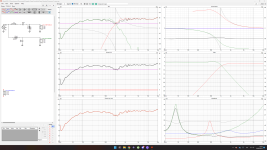
I just bought a Dayton Audio DATS V3. I know there are several previous posts regarding the use of this device. However, I just wanted to share my experience using DATS V3, and hope to get some feedback from people with more experience than me. At arrival, I quickly set up the DATS to run some T/S measurements on a handful of drivers I have laying around. These drivers are:

Scan speak 21W/8555-01 (4 pieces)
Scan speak 21W/8555-00 (2 pieces)
BMS 15S320 (measured only one)
Fostex FF85K (2 pieces)

Some observations:
  • I have four 21W/8555-01, which all measures pretty much the same (very high degree of consistency). All four woofers new in boxes. I broke in two them by simply running a low a freq. signal in free air for three days before measuring them. The remaining two came right out of the box (no brake in). All four woofers pretty much measured the same (only some minor differences). For all of them, Fs is very close to factory spec (meas. Fs = 19-20 vs. fact. spec Fs = 19). However, Qts is way off (meas. Qts = 0.37-0.38 vs. fact. spec Qts = 0.26).
  • For the two Scan speak 21W/8555-00, observations were similar to the observations for 21W/8555-00. Right out of the box, the two woofers measured the same (meas. Fs = 21 vs. fact. spec Fs = 20) and (meas. Qts = 0.44 vs. fact. spec Qts = 0.31).
  • Measurements for the BMS 15S320 was bang on factory specs (meas. Fs = 42 vs. fact. spec Fs = 41) and (meas. Qts = 0.29 vs. fact. spec Qts = 0.28). Also, this woofer came right out of the box.
  • Measured specs. for the Fostex drivers were quite different from factory spec. Higher Fs and Qts. I got these drivers from Planet10 some years ago, and they came with measurements performed by Planet10. By comparison, I got slightly lower Fs and Qts, but differences were marginal. That makes me feel somewhat confident that the DATS V3 works as intended.
I intended to make a FAST speaker system using the W21/8555-01, but I got somewhat concerned using the factory specs. I would very much like to hear from someone else with more experience on this topic.

Cheers

Best way to wire this power supply?

Hello

i have a power supply board here (already bought) (https://www.thel-audioworld.de/module/NT-HQ/NT-HQ.htm#NT25) that is able to provide symmetric power and im wondering if i could power a +9V dac with -4V/+4V instead of +9V/GND and if it would bring any potential benefit ?

another thing im wondering since these can act as 2 seperate power supplys ... my dac needs 9V and my headphone amplifier 18V, could i series both sides for 18V and just use one side for 9V at the same time?

(also any comments on the power supply itself are appreciated, is it good? and can it be tweaked further? additional caps?)

yet another *cube* enclosure

Hi folks,

The plan to make yet another cube enclosure with full range speaker. I know it's not the best but please bear with me.

Outside cube will be 18cm3. Internal wall will be 2cm thick with 4-layer perimeter and a 50% infill. Material will be black PLA. Outside will be sanded and painted, I want a piano black finish.

The front face will be made of 1 inch birch plywood.

I plan to use the Mark Audio CHR70.3 but I’m flexible if a better match could be found in the same price range.

Box will be closed back with some fill material, but it could be ported if desirable. I will use the speaker only near field in a small room. Port distortion, scuffle or other noise is a big no-no for me. That’s why I plan to go with closed enclosure and maybe add a subwoofer if I find the bass is lacking.

The big part that I need help is with the internal geometry. Maximum possible internal volume would be a 4L cube. However, since I’m printing it, I could easily make a cylinder, a demi-sphere, rounded corner, etc.

I thought going with the golden ratio, but it would reduce the internal volume to only 1L which is not desirable.

3L internal enclosure is possible with a demi-sphere design or a cylinder design. I’m not sure if losing 1L internal volume for that is desirable.

I could go the rounded corner route, which will have a lesser impact on the internal volume, but I’m not sure if it would help with the resonance or not.

What do you think would be the best to avoid the cube resonance issue?

Should I brace the speaker in such small enclosure ?

Thanks for you help 🙂

Look inspiration: Login to view embedded media PLA 50% review : Login to view embedded media

For Sale Precision Preamplifier PCB

Had some PCB's made for a preamplifier project. It is the "Precision Preamplifier" by Douglas Self, as described in his book "Small signal audio design". And after finishing this project, I have some boards left. The amp worked great btw, and I've only discovered minor error in the design (swapped "Hi Gain" and HI freq" text in slikscreen and too big lead spacing for two caps, but nothing that really mattered).

So if anyone is interested; I've got 4 pcs which I offer for €4 each + shipping (about €7 for Europe). There's schematic and BOM with Mouser part no's available too.

DM me if you're interesting.

Attachments

  • 20231009_180657.jpg
    20231009_180657.jpg
    840.3 KB · Views: 162
  • 20231009_204433.jpg
    20231009_204433.jpg
    633.4 KB · Views: 159
  • 20231009_204425.jpg
    20231009_204425.jpg
    744.3 KB · Views: 190

"Cube" box design FR and subs help

I have a bunch of "cube" shelves. They are 16in wide x 16in high x 12in deep. I'd like to build matching boxes for a set of speakers and subs.

The plan is to have 2 full range speakers, and 2 subs. I think I've settled on 8" all around, but I could do differently if that would sound weird.
I think I'll build them to look like the MasterSounds speakers since they are symmetrical and fit my "design limitation" (the cube shape).

I need help with the internals though. I've looked at a few different layouts/blueprints around but I guess I need a sanity check. Mainly I can't figure out why I would pick 1 layout over another. Like bass reflex, maze, single fold L, 4th order, 6th order, so on. based on MasterSounds they just list the Speakers as Bass reflex, and the subs as 4th order. Should I do the same? CAN I do the same? Do I even need to worry that much? I was thinking just doing it like this for the Speakers. And like this for the subs.

Linn Lingo vs. Dr. Fuß or Square-Wave vs. Sine Wave Oscillator for Motor Control

There are several motor control units (in Germany sometimes called wrongly "Power Supply") for turntables/record players with synchronous motor.
Most of them uses therefore a quarz oscillator (square wave), divider and low pass filter so as one or two power amplifier sections (mostly totem pole topology) for the motor coils.

But now I have heard about an other approach for higher spectral purity of the sine wave signal (i. e. lower distortion):
The Dr. Fuss motor control. Check therefore this URLs (control device with Wien-Robinson-Bridge sine wave oscillator section):
Erfahrungen mit Netzteilen von Dr. Fuss - fairaudio - leserbericht (1)
Dr. Fuss Motornetzteil - Frank-Landmesser.de

The circuit describtions for such an oscillator circuit you will find there:

http://www.ti.com/lit/an/sloa060/sloa060.pdf (page 17/18)
Types of Quadrature Oscillator | eHow.co.uk
https://web.archive.org/web/20130615120921/http://www.mics.org/getDocum.pdf?docid=1332&docnum=1
Quadrature Oscillator (Part 1) | Liivatera: Diary from the workbench
Liivatera: Diary from the workbench
http://www.ti.com/lit/ds/symlink/lm4766.pdf

Dr. Fuss uses either a Wien-Robinson-Bridge or a Bubba Oscillator/Quadrature Oscillator/SVF ( according TI "Wein bridge Oscillator" resp. "Wien bridge Oscillator") and an audio chip amp, model LM4766TF from National Semiconductor.
Attached PDF in post #16 under
Homebrew Motor Control Linn LP12 - Circuit Description wanted for Sine Wave Osc.
shows a schematic of a clone from Dr. Fuß motor control - based on a state variable filter topology.

Linn uses fore the LINGO two quarz oszillators and two power amplifiers for 33 and 45 rpm and for the Valhalla PCB one oscillator and one power amplifier so as an additional capacitor for the second coil (phase shift) - go to the attached files.

What are the pros and cons of both ??

Thank you for your comments.

Attachments

A ON/OFF AXIS brain storming and influence on bass response

Hello, welcome! I'm back in that unhealthy vortex of dissatisfaction that is created when you try to listen to music and you are convinced that there is a way to listen to it better. I've had a pair of old but good MTM transmission line tower speakers for a while now, so far listened to in my living room in a 'calm' state, all ok, but perhaps 'too ok' in the sense that I a little bored, and I said to myself: why don't I do some measurements to see if I can liven something up? I then saw that in my opinion the Morel was cut too high, thus losing much of its expressiveness, and causing, again in my opinion, a bad off-axis response, because the mid-high range was entrusted to the midwoofers (Vifa 6.5'' ) up to too high; also the time alignment was good but could be improved. This is what I achieved with fairly simple changes (also perhaps understanding how to avoid the mistakes I made before which always led to sibilance problems):
original.JPG

ORIGINAL situation

modified.JPG

MODIFIED situation

overlay.JPG

OVERLAY of the two (I attach the simulations only for the convenience of superposition and because they are quite faithful to the measurements, which only have a more regular and flat trend)

A more open and emotionally engaging, dynamic, 'fresh' and pleasant mid-high range, which in my opinion exploits the expressive potential of the beautiful Morel much more.
Furthermore, I also installed 5 cm sound-absorbing panels on the rear wall behind the speakers, which are approximately 35 cm from it, for a height and width equal to the height of the speakers; the mouth of the transmission line is on that side about 35 cm from the ground.
The problem is that now I can hear the basses well everywhere in the room... except the listening spot on the sofa in the middle of the living room!! When I sit there, the bass disappear into thin air, if I walk around they reappear in all their beauty.

My question is: what could this phenomenon depend on?
  • from the fact that the off-axis response has worsened rather than improved as I expected (and therefore I haven't understood anything about it so far), and then I 'feel' the mid-high range stronger only on-axis?
  • from the fact that before I was more careful to 'look' for beauty in the medium-high range and didn't care about the low range? Yet I am convinced that there wasn't that much difference in bass between sitting and standing....!
  • from the installation of sound-absorbing panels?

Thank you to all!

For Sale Wood frames for tube amplifiers

These are "raw" High quality american walnut wood frames + 3 mm thickness aluminium top plate + perforated aluminium bottom plate.
Dimensions are:
390 mm x 450 mm x 80 mm.........3 units
260 mm x 580 mm x 80 mm.........1 units

Price per unit ......140 euro + shipping anywhere......
Thank you.
I use them into these projects:
https://www.diyaudio.com/community/threads/el34-baby-huey-amplifier.326920/post-7380662

1.jpg

Attachments

  • 2.jpg
    2.jpg
    185.7 KB · Views: 91
  • 3.jpg
    3.jpg
    200 KB · Views: 86
  • 4.jpg
    4.jpg
    335.6 KB · Views: 91
  • 5.jpg
    5.jpg
    292.7 KB · Views: 81
  • 6.jpg
    6.jpg
    231.8 KB · Views: 91
  • 7.jpg
    7.jpg
    279.8 KB · Views: 87
  • 8.jpg
    8.jpg
    313.4 KB · Views: 87
  • 9.jpg
    9.jpg
    289.6 KB · Views: 86
  • 10.jpg
    10.jpg
    306.6 KB · Views: 88
  • WhatsApp Image 2024-04-05 at 21.09.27_f472b2ca.jpg
    WhatsApp Image 2024-04-05 at 21.09.27_f472b2ca.jpg
    428.7 KB · Views: 30

USB-output to USB-input?

I'm considering using a small machine (such as a thin client or SBC) to make a digital crossover with EQ. My source is a bigger desktop PC, providing sound from several different applications. Both machines would have USB connectors (and preferably be running Linux, if that matters). From my initial searching, it seems that most people would use audio interfaces/converters (e.g. toslink) to make the link; plugged into the USB ports at each machine.

Is there no easy way to stay with native USB for the link, or if not would the conversion to toslink (or similar) and back again make little/no audible difference?

Thanks,
Kev

Totem Mani-2 opening cabinet

Anyone have any experience opening up the rear of the cabinet? Several Screws removed but tolerance is so tight the panel does not want to come loose. Remarkable build quality but I need to access the tweeter which will not come loose either after removing its screws. Sure I can pry the tweeter or read panel but I risk damaging the veneer . Looking for suggestions . Thanks !

XA30.8 gate resistors

I own an XA30.8 and noticed that the gate resistors for the output devices seem quite high in value (don't recall the exact value - would need to open the amp up to check, but I remember they seemed high, maybe several 100 ohm each).

Since I have previous experience with lowering gate resistors which seemed high in value with favourable results (significantly more transparent sound), I was wondering if I should do this here too. Is there anybody here who has tried this. on any recent Pass amps?

Please share your experiences!

Thanks,
Alexander

Linn Switch Mode Power Supplies (SPS/SMPS) - Schematic Overview wanted

In the meantime there are a wide range of different SMPS versions from Linn - usually suited for various Linn (pre-) amplifier models.
Until now Linn don't support any repair efforts of the user's - even the delivery of any circuit diagram is refused, because Linn claim, the replace of the whole SMPS module provides best reliability.

The actual reason, however, is to avoid under all circumstances that the presence of deficiencies on circuit design - which are clearly present - come to the public.
The main deficiencies are thermal stress and/or inferior parts (mainly bad caps, both in leaded and SMD version).

It has been increasingly common for about 15 years to offer low-quality products with a very high-quality exterior very expensive (sometimes extremely expensive) - btw in all specialist areas of products and not only in the home audio area.

The question is, how many technical guys have create schematics (reverse engineering) of their Linn power supply versions - in the kind of this "Brilliant" schematic, which I have create several years ago - go to post #5 under
Linn "LINTO" MC Preamp Schematic without SMPS - Schematic for SMPS wanted

Maybe on Linfo so as the Linn Forum are own creatings of schematics (maybe of various power supplies), unfortunately this URL's don't longer exist because Linn closed both - additional also not to find by webarchive.

2-way horn system based on the MK3B2

My speaker quest started off with grand ambitions of finding a fancy 3 or 4-way active setup. Luckily, @vineethkumar01 , the voice of reason, drilled some sense into me, urging us to go for something simple enough with better chances of success (or lesser chances of screwing up). The goal was to create a high-efficiency horn-based design, complete with active crossovers and DSP.

Enter @vineethkumar01 , the bringer of audio enlightenment, who mentioned this brand spanking new redesign with improved directivity of Yuichi Arai's 290 called the mk3b2 Radial Fin Horn, a collaborative effort from the minds of @DonVK , @docali , and @fluid (The thread can be found here). We didn't waste any time, we quickly decided that this was the one we were going to attempt. And so, we begin this project with a dash of enthusiasm and a sprinkle of uncertainty!


Particulars:

Action sequence:
  1. Build the horn first. Which will include 3d printing and CNC.
  2. Design and execute the adaptor for the CD.
  3. Design and build the BR cab to suit the horn dimensions.
  4. Extensively measure the horn and create a full spinorama.
  5. Set the crossover and tune with DSP.

Are your heatsinks sold in the market really flat?

Good day everybody.

I have many heatsinks of various sizes. Some reclaimed from older equipment and many bought from reputed sellers and eBay etc.
I check the flatness of the heatsinks using a flat ruler or square prior to mounting components.
Those recovered heatsinks are truly flat and can be reused. Those purchased from online or local shops are not that flat.
I have to sand the uneven surfaces to make any use of them.
What is your experience? Do you check them also? How you make it flat?

Regards.

Path to noiseless Linux streamer...

After now 20 years of building different DACs and playing with different streamer, I finally ended up with Andrea Mori's Clocks/ FIfo and DAC...which brought a level of realimns and transparency to my system which called for reviewing the source. Until today the reference has been an Alix 1D, Sotm Usb-Card, linear PSU and MPDpup, a very lightweight Puppy derivate where many good people fine-tuned this to the best...second best distro I heard until today has been Archphile.

Unfortunately, my hardware is old and none of these distros are maintained any longer, so I started a new approach:

  • "Universal recipe": ARM, x86, Raspberry, NeoPi: Should serve any platform and any Linux "dialect"
  • Target to play PCM-files, so no real-time application like for a musician, this is about
  • Lowest Noise primarily and lowest jitter secondaraly, Lowest latency in itself is not a reqirement at all.

The Linux Kernel brought with 5.15 a new tracer (RTLA)to trace OS-Noise and Latency in a white box approach, so you can easily make your Kernel configurations or system modifications visible....this is a HUGE help to see what does what...and we can now truely measure OS-Noise, so it is not a philosophical believe question.

Have a look just as an example on the osnoise effects of binding tasks to CPU-core vs. isolating the core vs. true tickless operation:

NOISE.png
From H. Akkan, M. Lang, L.M. Liebrock, Stepping towards noiseless Linux environment)

The RTLA-Osnoise tool is very powerful, it shows you the noise effect of anything you try per CPU-core be it threadning IRQs, isolating core, assigning and priotizing task or running a tickless Kernel. I invite anyone to try it.

Sofar there is a very strong correlation in my experiments between lowering OS-Noise and better, more direct, more transparent SQ with richer tone at the same time, some people would call it "analog" sound...you can measure as well the effects on OS-Noise of

  • isolating cores for your player
  • Using flac vs. wave
  • hardware vs software volume mixer
  • resolution of your files
  • network vs. direct stored files

and many more.

Additionally, I found that in Linux Core 5.15 (and versions after), some very interesting topics have been added for the audiophile:
  • Rewritten USB-driver for lower latency
  • Dynamic switchable PremptionModel (none/voluntary/full) at runtime
  • ALSA using HR_TImer as default

For my experiments, I started with Debian Bullseye as I can easily generate my own kernels for nearly any platform using DIetpi or Armbian as a starting point. It is really very easy and I am happy to share the how to if there is interest.

There are two different categories of settings:

A. Those which are difficult to negelect or argue about their positive efffects, any Linux streamer would benefit from them
B. Those where it is a matter of personal taste, your way of listening

Lets start with A.
These are setting which not only from a theoretical and OS-Noise-Measurement PoV make a difference, but which I found easily audible (in my system suing a N5100 fanless MiniPC):
  • usage of a linear PSU is a a prerequisite for anything.
  • usage of log2Ram or equivalent recommended
  • use the USB-Port which comes from your SOC-Cpu and goes not through an extra third-part Controller (e.g. many MiniPC which a Z8350 have the one USB3.0 port from the Z8350 and some more USB2.0 from an external chip)
  • Isolation of CPUs giving Ethernet to one core, USB to another and MPD on the third, any other IRQ or App runs on CPU 0.
  • DIsable frequency scaling of the CPU, use userspace as governor with fixed frequency
  • 1000 Hz timer frequency (which is normally only use with the Realtime PAtch, but here we use it without the overhead of the RT-Patch)
  • nohz_full (full tickless mode)
  • ALSA using HR_TImer as default
  • echo 2048 > /sys/class/rtc/rtc0/max_user_freq
  • echo 2048 > /proc/sys/dev/hpet/max-user-freq
  • MPD running as a service with FIFO-RT scheduling Prio higher than 51 and higher IO-Prio (brings OSnoise down by 30%)
  • If you can, avoid using a network. HIgh OS-Noise and directly streaming from an SSD sounds much more direct.

And here is my current list of B. topics which are audible as well, but a matter of your personal taste:
  • Preemption Model: I prefer None to Premption voluntary or Full. None Sounds more direct more resolved, but a bit dirty. Full sound a bit damped and controlled, not as spontanious, in transients but very clean and warm.
  • TSC vs HPET clocksource: Difficult. HPET is more musical, more rounded but less resolved sounding. I prefer TSC and set the KErnel option tsc=perfect to avoid any overhead.
  • These two Prememtion Model and clocksource are interesting to combine in different ways as the crystalline sound of TSC goes nicely as well with a stronger preemption model...but I like it as resolved as possible,

Thats is where my efforts stand at the moment...next on the list:
  • Compare x86 with many ARM-devices with the same Kernel-Settings
  • Start to look into I2S directly like NanopiNEo3 seems to be supported directly by the Kernel, but each I2S implementation is board specific...there might be reasons why one boards sound better over USB than I2S and on another its the opposite.
  • Compare Audio-Linux and Archphile at some point of time to this generic Debian-based solution...to see where we stand.

I am happy to share any level of detail how I did what if there is interest. I am very eager to learn from others and their findings I could try myself in my setup additionally. I am not interested at all in generic discussion about "All Sources sound the same" or "A fifo will make any source sound the same" etcetc... that is a waste of time and energy.

So, the purpose of this thread is really to get to a modern alternative to archphile or MPDpup for any platform and for any Linux-version usable. And sharing knowledge, saving you time.

"Wandering" Distortion?

I am not sure if this is the correct forum / place to ask this question. If not, mods, please move.

I am just now starting to get my feet under me when it comes to understanding some facets of even the most basic measurements, how to do them properly / consistently, and most importantly how to understand and apply what I see in all the pretty, pretty, pretty charts and graphs.

I ran into something this morning that I haven't seen before, and it fascinated me. I was measuring my first "real" amplifier that I got back from a friend recently. It carries a lot of nostalgic value to me. So, I was going to put to use all my new and wonderful DIY knowledge, clean it up and possibly give it a refurbish. I am reluctant to even recap a commercial amp, so I wanted see how it was currently performing. Overall it seems fine. 0.00 VDC offset, stable for 24 hours, and basic performance measures seem in-line with expectations.

But...

Here are a few plots of the distortion residual. The reason they're not really tight across just a few waves is that when I was watching it "zoomed out", it was clearly varying in a pattern over time, while the signal remained stable. The software sets the scale for the residual vs. signal automatically. So, the residual isn't varying dramatically (relatively speaking) over time, but it does "swing up and down" in a pattern.

In all the vastness of experience (HA!) I have measuring 6 or 7 other things around the house for fun, I haven't seen this before. All the other amps are FW clones, a BA-3 variant, and my Sony VFet. For all those amplifiers, the voltage of the distortion stayed 'flat' for lack of a better description vs. the average across a few ms wandering up and down. I wish I could describe it in more accurate terms. I can take a video also if it helps. This amp may have a servo. I am wondering if this type of behavior is associated with a servo correcting for offset... (The amp is an Aragon 2004 from circa 1995).

Why do I care and ask? I'm curious, and I haven't seen this before. We tend to look at "static" images of the residual and/or the FFT. Since I typically go with the idea that what we distinguish in amplifiers is mostly due to the distortion (all other things remaining equal)... I was wondering if I was off my rocker. If we accept or consider that a few mV of distortion with a certain pattern against a much larger signal affects our perception of the sonics of an amplifier... I am wondering if the distortion profile "wandering" up and down is normal for some amplifiers and its potential effect.

Listening tests with my ears likely won't reveal too much, but I've become fascinated with "what the distortion looks like" in a manner of speaking. Possibly a rabbit hole not worth diving into, but ...

Thanks in advance for any insight and ideas for how to understand what's happening and why...

Cheers,
Patrick

Attachments

  • 1W 8R Residual Zoom Out ... Servo 2.jpg
    1W 8R Residual Zoom Out ... Servo 2.jpg
    295.8 KB · Views: 113
  • 1W 8R Residual Zoom Out ... Servo 3.jpg
    1W 8R Residual Zoom Out ... Servo 3.jpg
    296.3 KB · Views: 105
  • 1W 8R Residual Zoom Out ... Servo.jpg
    1W 8R Residual Zoom Out ... Servo.jpg
    296.6 KB · Views: 103
  • Like
Reactions: twitchie

Discussing about 8channel DSP using Camilla DSP + Raspberry PI -- Interface options

Hello,
and sorry in advance for beginning just another topic about multichannel DSP using CamillaDSP. But the questions I have are not answered so far. My intention is the implement a Stereo 4 way active loudspeaker system (8 channels in total). Initially my plan was to use analog active crossovers. But the limitations doing this are there. Hence I searched about DSP solutions and came across CamillaDSP, a great project.
Besides using very expensive multichannel sound interfaces (RME for example) I considered other solutions and hopefully get a feedback to this from the forum. My most important concern is timing accuracy. The individual channels must not have a timing error >10us (assumption) to reduce phase shift in between.
My elementary need is to have 4 I2S / Toslink IOs for using 4 fully digital AMPs (1 for each frequency band).

* according to my understanding using 4x Raspberry Pi and 4x Digi+ IO boards should do the job. The audio signal is split using a 1x4 TOSLINK splitter, all Raspi get the same input data stream, each Raspi only has its own filter and some delay to make all ways equal. As I understand the situation timing should be no issue because input and output audio is synced by the (common to all) I2S input clock.

* using 1x Raspberry Pi and 4 USB sound devices: as far as I know JACKD can be used to implement a aggregate sound device. 4x 2 channel devices give 1x 8 channel virtual device which can be used in CamillaDSP. Of course USB timing and delay is not known because of its asynchronous nature. But what can be said about the relative timing in between the USB devices? Does JACKD guarantee that there is no timing error in between them? If this is not the case what is the sense of the aggregate device?

* using 1x Raspberry Pi and HDMI 7.1 audio extractor: this implementation should give no channel relative timing error at all.

Perhaps here are some experts who can comment on this. Most likely this is a questions many others are interested in as well.
Many thanks in advance...

Stephan

HexiBase 3D Printed mini subwoofer, redux

As many in this forum will know, a couple of years ago youtuber HexiBase built several 3D printed subs using the Tang Band W3-1876S 3" subwoofer. I was very interested at the time, but the lengthy 3D print was a problem for me. I got the idea to make a version of his design that was hollow on the inside, so it would print much faster and I could then fill it with concrete. I got as far as making the 3D model, but then life got in the way and I all but forgot about the project.

Fast forward 6 months, and youtuber DIY Perks posted a video where he did pretty much what I had in mind (Fill a 3D printed speaker enclosure with something pourable) only using his own speaker design. He also use concrete, but plaster of paris with PV glue mixed in. This gave me the kick in the butt I needed, and I bit the bullet.

I ordered the Tang Band driver, finished my HexiBase redux design:
HexiBase subwoofer redux Hollow filled with plaster - Imgur.png


And kicked off the 3D print:
IMG_7839.jpeg


It took quite a while (39 hours), and it's far from the cleanest 3D print I ever did, but eventually it was finished:
IMG_7847.jpeg


After a test-fit to see if the driver actually fit it was time to fill the enclosure it with modelling plaster. I used the orbital sander in the background to vibrate the enclosure while pouring to convince any air-bubbles to move to the top:
IMG_7855.jpeg


And here's the sub after curing in its natural habitat:
HexiBase subwoofer redux Hollow filled with plaster - Imgur.jpg


And this is what the plaster-side looks like:
IMG_7858.jpeg


This is a temporary setup, since I don't have a 2.1 amplifier, or something similar. Not entirely sure what I'll do yet, but right now I'm investigating a Teensy-based DSP + I2S DAC. I don't have any measurements or anything, but even with this temporary setup I subjectively get a much better bass sound than with just the KEF Q150's I have.

Feel free to ask any questions you like. If there's interest I'll happily publish the CAD and STL files on printables.

Help choosing the right resistors

hi.
can someone explain me what resistors do i need to get for my crossover? i have 2 questions

1. do i need a 10W or 20W resistors? this are the only W options i found (woofer=4 ohm 40W RMS. full-range woofer=8OHM 10W RMS)

1696970064467.png


2. what is the meaning of this 1OHM resistor (marked in the picture)? it dose not seem to change the output on VituixCAD, this crossover is based on a design from the software lib.

this is the layout
1696970180161.png


Peace and love

My MOTU UltraLite journey

I recently purchased a motu ultralite hoping to use it to replace a behringer DCX I use as a crossover for my 4 way speakers. This post I hope will be helpful to others who want to use the motu.
The cliff notes so far is if you want to use a pi, it must be a 4. Mine is a 2GB version running 6.1.21-v8+ #1642 64 bit and not sure if
it mattered, but the motu was plugged into a USB3 slot. I'll try to answer any questions about the config if you are trying to get an ultralite to work on a pi-4.

The motu is significantly better than DCX from all reports. My plan was to use a pi-3 to drive the motu using Camilla as the brains for the crossover. The plan took a many twists and turns. Using the pi-3, recording would either go dead or freeze with a tone. Playback also would freeze with no tone although the meters on the motu would show a constant signal. Not good. I dug some, changing O/S version, tweaking ALSA, and numerous other dead ends I don't remember anymore. Next up, I tried it on my linux laptop. Competely dead. The laptop is running 4.15 kernel with ubuntu. Next up, I picked up a windows laptop to try that. That worked, but with caveats. Capture worked for 2 channels, so I did some captures of my SACD's and may use it to capture some vinyl. Output is a no go though I think. Windows shows the device as multiple devices with 2 channels each. I think for Camilla that will not work. I thought Camilla wants to see all channels as one device. Its sort of ok, as my ability to stomach windows may have ended up making it a no go anyway. After some 40 years of *nix O/S's, windows is just not me. Anyway, as it happens, I'd ordered a pi-4 back in November and Digi-key sent me a notice saying it was shipping. I'd kind of forgotten about it. So I took the SD card out if the pi-3, put it in the 4, booted and plugged in the motu. To my delight, it just worked. I'd already discovered the motu using usb audio class compliant that linux uses forces sampling rates/channel counts. 44.1/48 is 22 channels, 88.2/96 is 18 channels and 192 is 10 channels. I'd already planned on using the 96/18 channel mode which gives me access to the headphones, all 10 analog outs and 6 digital outs which I won't be using. As a test, I drove the motu with a digital sine wave and captured it using a scarlett box. After an hour, perfect sine wave still coming out of the motu. So I think whatever it did not like in the pi-3, the pi-4 hardware fixes the problem.

My next step is to get Camilla setup to what my current DCX settings are set to and start moving to the new setup. This means I first must decide balanced or SE from the output of the motu. The motu is balanced out and all my amps are single ended. My understanding is the motu provides the best performance in balanced out, and I do see a very slight degradation using REW and looping back the signal fully balanced verses only using the +/shield to drive the motu input. The difference is very slight though, THD+N is .0030 balanced versus .0032 SE. The difference is larger when only considering distortion, .00095 balanced versus .0011 SE. And low frequency noise from 20-100Hz is about 10db worse at 20Hz and trends to the same by 100Hz. So not sure there is any value in building a balanced to SE converter that may well be worse than just using the + only output of the motu

Well that is it for now. Just happy I got the box working. I was really close to giving up and selling it.

JL AUDIO A1800

Hello
I have a jl A1800 amplifier. I had all the source fets and drivers damaged. I already changed the 3525 one new and one used.
The problem is that I do not have high voltage on the 63v 3300uf capacitors
UC3525
Pin 1: 0.002
Pin 2: 5.008
Pin 3: 0.260
Pin 4: 0.430
Pin 5: 1.863
Pin 6: 3.76
Pin 7: 1.778
Pin 8: 0.085
Pin 9: 5.75
Pin 10: 0.049
Pin 11: 0.003
Pin 12: 0.001
Pin 13: 13.21
Pin 14: 0.003
Pin 15: 13.21
Pin 16: 5.08

Event ASP-8 Problem / Diagnosis

My father-in-law has a set of Event ASP-8 monitors that I've fixed before. They get so hot that the board expansion caused some of the board-edge SMD caps to fracture. I soldered on new ones years ago and added a big heatsink to the back of it, and it seemed to work pretty well for several years. I'm not an expert, but I'm the family expert, if you know what I mean. I know these monitors are plagued with problems, but he likes them and I'd like to keep them working as long as possible.

However, one of the speakers is now acting up again. Behavior is as follows: Intermittently changes randomly between wayyy too loud, a more normal volume, and totally muted. Not sure if the levels are discrete or if it's an actual random volume. It happens on both the high and low end outputs. I've run a frequency sweep with input audio and I've also isolated the woofer and the tweeter and it definitely happens on both, so I doubt it's far down the signal path. I've checked the rails from the crappy power supply and they do seem pretty steadily at +-18VDC, even when the problem is occurring, so I doubt it's the problem.

Looking at the schematic, I'm guessing it's in the front-end/initial opamp/crossover area, since that's common to both low and high frequency. It does not seem to be the input connectors. I'm guessing it's not one of the ceramic SMD caps since, in my experience, they fail open, maybe closed, or somewhat predictably oscillate, and it's also not an issue that's sensitive to pushing or tapping on different parts of the board. Also, I checked the gain knob and it seems to be fine.

My guesses are that it's the front-end/crossover op-amp that got fried/out of spec, which I guess is common on these boards. Or, it's something in its feedback path, but that seemed unlikely to me based on what I know about SMD cap failures. The resistors all seem fine. My only other guess is that, despite the signal path being somewhat isolated from other parts, there could be something wonky still happening with ground, the power supply, or something else common to both channels. The fact that it is so intermittent and random in presentation makes me think it's something with silicon, though, but I don't know if that analysis is BS or maybe I'm missing something obvious. I haven't hooked up a scope to it yet, but maybe that's the next logical step.

I have ordered a drop-in replacement opamp for the original (which is a OPA2134) to figure out for sure if it's the culprit, but I wanted to just see if anyone else has any ideas.

Thank you.

Edit: Can find the service manual at https://dokumen.tips/documents/event-asp8-service-manualpdf.html or lots of other places

Steg K204 blinking protection

Good morning everyone.
In my hands I have a STEG K2.04 with green LED on and red flashing.

Let's get to the point: The amplifier had an entire channel shorted, so I removed all 14 FETs (FQP22P10 and FQP33N10).
I also removed some transistors of the preamps as they had values out of tolerance.

In theory, since nothing is shorted anymore it should turn on, but instead it doesn't.
I then tried removing everything from the second channel too, but the problem persists.
By measuring the microcontroller(ST7LITE1) that manages the protection, I noticed that in the PROTECTION pin, +4.9V is present even if I lift that pin from the PCB. (In the K2.02 diagram I should find +5V in input not output)
I assumed it wasn't exactly the pic that was generating the problem, but by separating the switching board and the amplification board (they can be divided using screw terminals and a flat) and keeping them connected only through the flat, as soon as I apply a voltage on the REM, the amplifier starts and is no longer in protection.

I have a feeling that some RAIL voltage checking is done and for some reason it fails.
Does anyone have any idea how to test the microcontroller?

ST.JPG

Help with BrianGT chipamp power supply

Hello, I am tearing my hair out trying to figure out the wiring on this LM3886 power supply. I think that AC1 and AC2 are each a pair (0v 18v) secondaries and that the lower board connection is 18v and the one above 0v on the left of the board and the same on the right but they are not marked and I don't know how to test the MUR860. I have been going round in circles and started relatively confidently but now am completely confused. I assembled the boards 12+ years ago so would like to finish them 🙂 Any help will be hugely appreciated.

Attachments

  • IMG_20231010_172705.jpg
    IMG_20231010_172705.jpg
    509.6 KB · Views: 139
  • IMG_20231010_172149.jpg
    IMG_20231010_172149.jpg
    262 KB · Views: 133
  • Screenshot_2023-10-10-15-31-10-045_com.android.chrome.jpg
    Screenshot_2023-10-10-15-31-10-045_com.android.chrome.jpg
    110.5 KB · Views: 123
  • Screenshot_2023-10-10-15-31-10-045_com.android.chrome.jpg
    Screenshot_2023-10-10-15-31-10-045_com.android.chrome.jpg
    110.5 KB · Views: 124

For free pickup in NYC Area SVS 20-39 sub and external plate amp

I hadn't turned it on in 10 years so I guess I don't need it anymore. This is the unpowered SVS 20-39 cylinder sub, with an external PartsExpress (or was it Partsconnexion?) generic plate amp. I have the original paperwork for the amp, but the speaker itself was bought used. The original owner didn't use it much either. I've vacuumed the accumulated dust from it so it is clean. The amp uses the original egg cardboard box it came in as a mount. One thing I don't seem to have is the power cord for the amp, but any IEC cord will work. I had to use my computer's cord as I just couldn't find one.

It is free for pickup only in Brooklyn, NY. I will NOT ship, I will NOT deliver it. I can barely lift the thing anymore. Don't kid yourself either, the thing is big. If you live in a typical Brooklyn apartment you're not going to want this, and neither do your neighbors. The 20-39 refers to the diameter and height, or maybe hz and height, but it is 20" in diameter too and goes down to 20hz.

Free, but a decent bottle of wine couple of beers are always appreciated in trade.

For Sale AD1865NK Analog Device Genuine

I have 4 Analog Device AD1865NK that I don't need. All four AD1865NK I have since 2007, so I have no reason to believe they are not genuine and in perfect order. Asking 45€ for one. The price does not include PayPal and shipping costs. PayPal is accepted, registered mail order buyer pays the additional 5% PayPal fees. With PayPal Freund the 5% does not apply and can be sent without tracking, the shipping costs within the EU are approx. 15€. Shipping within Germany €6 Outside the EU it may vary by country. I can combined shipping. If you are interested send me a PM.

Attachments

  • AD1865_NK (2).jpg
    AD1865_NK (2).jpg
    370.6 KB · Views: 126
  • AD1865_NK (3).jpg
    AD1865_NK (3).jpg
    320.9 KB · Views: 142
  • AD1865_NK (4).jpg
    AD1865_NK (4).jpg
    442 KB · Views: 116
  • AD1865_NK (5).jpg
    AD1865_NK (5).jpg
    458.1 KB · Views: 121

Tesla Coil " Speaker "

Hi, I built a few tesla coils for fun in the past, nothing big or fancy. But I want to try out a tesla that can play music, came across this schematic from a ebay kit .
I know it is a "slayer exciter " that oscillates by itself, the secoundary coil providing feedback into the Base of the transistor trough the " capacitance of top load trough air " and it is " modulated by the mosfet something similar to AM radio if Im not wrong, but I have a few questions about the schematic:
  • Shouldn't D1 be from base to ground instead ? ( in LTSpice it does not work with it as in the schematic, WHY ? )
  • what does C2 do ? from Q2 to ground. ( in LTSpice it reduces substantially the output voltage, or does not work at all,. depending on the self oscialltin freq ( increasing Cx would make it work. )
  • R5 and LED 2 are some sort of " protection " for the mosfet ? ( I added a zener diode from gate to source to keep the voltages in range and not kill the mosfet, I think I put it correctly there.
  • Coil I have built long time ago, around 1000 turns 0.12mm wire . 14x3 cm plastic tube.
it has 3.3mH

Please explain to me what these components really do, and maybe help me improve it ?.
Thank you , Bruno!.

Also sorry if I posted in the wrong section .

Attachments

  • tess.png
    tess.png
    129.8 KB · Views: 178
  • teslaaaa.png
    teslaaaa.png
    137.4 KB · Views: 176
  • Simuv1.JPG
    Simuv1.JPG
    47.9 KB · Views: 190
  • 20231011_063951.jpg
    20231011_063951.jpg
    227.4 KB · Views: 148
  • 20231011_070414.jpg
    20231011_070414.jpg
    276.9 KB · Views: 144
  • seemstowork.png
    seemstowork.png
    32.2 KB · Views: 152

Hifonics A3000.1D

Hi all,

I have a hifonics alpha 3000.1D that goes directly into protect upon connection of remote power. Nothing on the board looks bad to the naked eye. All of the FETs measure OK.

This amp uses the TL494 for the power supply. I've checked all the SOT23-3 transistors near it and they all "measure" OK. Of course they could've failed in an open state.

I'll check the voltages going into the 2 opamps of the TL494 tomorrow. Does anyone have a schematic for this guy?

Attached some pictures of the amp.

Attachments

  • IMG_1278.jpg
    IMG_1278.jpg
    592.8 KB · Views: 119
  • IMG_1279.jpg
    IMG_1279.jpg
    645.2 KB · Views: 122
  • IMG_1280.jpg
    IMG_1280.jpg
    669.8 KB · Views: 115
  • IMG_1276c.jpg
    IMG_1276c.jpg
    626.8 KB · Views: 127

Rotel 1412 troubleshooting

I had a working ra-1412 that ended up blowing three output transistors. I have gone over and over it and I feel like I am running in circles. Transistors, emitter resistors, and everything I test seems fine. Then I discovered if I unhook e1 wire from the right main amp board, no short. E1 is connected to the phono board. Should I be looking at the phono board?

Attachments

  • image.jpg
    image.jpg
    497.3 KB · Views: 96

Turning an amplifier on after sitting idle for a while

Greetings!

I would like to turn on my Akai AM-95 after it has been sitting idle for more than a year and do the maintenance it requires, i.e. replace a defective potentiometer that proved time-consuming to source.

As far as I understand, applying full mains voltage might be a bit too much for some of the electrolytic capacitors... I don't have a variac, but have several incandescent bulbs of different wattage, starting with 15W.

Would the dim bulb be the way to go? Any cons to this approach?

Thanks 🙂

Antek Balanced Isolation Transformer Units

I just noticed that Antek is selling balanced isolation transformers with filtering and Faraday shield for very reasonable $. BP-400 at $155, BP-600 at $175, and BP1000 at $195. I think they do not sell the balanced transformers separately, but there seems to be enough space to allow some modification. like adding MOVs/GDTs. Unclear if the outlets can be replaced. Any thoughts?
  • Like
Reactions: uncola

AD1862N Chip's N Dip for sale

Hello,

------------------------------------------------------ORDER WAS UNSUCCESSFUL-------------------------------------------------------------------


This is the current situation. I apologize if this caused any inconvenience for you. I will update as soon as possible
https://www.diyaudio.com/community/...st-tht-i2s-input-nos-r-2r.354078/post-7248352


I have 14 AD1862N on order from DigiKey. There will be 12 up for sale, 6 pairs. I should have them in about a week. Limit is 2 Pairs per person.


Price per pair – $52

+Plus+

Shipping inside USA – $14

OR

Shipping outside USA – $22


If you are interested please send me a PM including your

1. Paypall Name

2. Shipping address

Payment requests will be sent once I receive the package from DigiKey. Packages will be insured. Once your package is shipped I'll send you a PM. Shipping from NorthWest Arkansas. I will reply to PM's after 6 on weekdays.


Thanks 😊

North

Western Driver/Receiver 3013 - C or 3015 - C (???)

Hello,
I'm new to this forum and was looking for a bit of advise re the driver in the attached photos.
I was gifted a homemade speaker unit from a musician friend who's uncle had built this himself some years ago.I'm assuming the model number is Western 3013 - C or 3015 - C but not sure as I can't seem to find any information on such models. Does anyone have any idea as to the details and what the actual model number is?

Many thanks

Attachments

  • IMG_3371.jpeg
    IMG_3371.jpeg
    587.5 KB · Views: 154
  • IMG_3370.jpeg
    IMG_3370.jpeg
    667 KB · Views: 286
  • Like
Reactions: Arez

Built the Protodac and have a question regarding using clocks from DIGI2 pro

I am working on a project making the NOS dac based on the TDA1387 x8 parallel chips.I had it as a dac hat on a Pi3 and just recently because I like it that much I have installed it all in a sharp case and sperated the boards instead stacking etc.My next step was I wanted to get a better clcock as its using the Pi master clock now. I own a digi2 pro, I cant find any reclocker boards on used market then dawned on me the DIGI2 pro has dual clocks high precision. I want to know if I can feed the clocks from the DIGI2 pro GPIO pins to the GPIO pins the protodac uses for clocks. THe DIgi2 has a header allowing it to be used with other hats including their DSP board. I cant seem to find a solid answer. From Hifiberry site regarding pin out of DIGI2 pro

HiFiBerry Digi+ Pro, Digi2 Pro​

GPIO2-3 (pins 3 and 5) are used by our products for configuration. If you are experienced with I2C, you might add other slave devices. If you a a novice, we don’t recommend this at all.
GPIOs 18-21 (pins 12, 35, 38 and 40) are used for the sound interface. You can’t use them for any other purpose.

GPIOs 5 and 6 are used for the clock circuit and cannot be used for anything else.


ANy help appreciated.
  • Like
Reactions: tamra

antimatter falls down

Finally, an article..
https://www.nature.com/articles/d41586-023-03043-0

Maybe 8 years ago, the lead scientist called me to ask how much it would cost to make a new antimatter trap magnet. He wanted to know if it scaled with length, as the new one needed was a lot longer. I said, not sure, it might be less than linear, as straight lengths were a bit easier than the corners.

He also said... oh, by the way, it will be mounted vertically... to which I said, "oh, you're testing gravity". Suddenly, dead silence on the phone... It was a secret.
(note. The actual magnet had significantly more coils, with accuracies below .001 inch, it was a bear to make..)

End result.. we built the magnet and didn't know what was going on for roughly 3 to 5 years..

Published, cool results.

The techs I work with are the best in the world.. This could never happen without the skills of the two guys who did the work. They are awesome, I am in awe.. Actually, my words to them as I shook their hands were.... you are "effin" great. (nanny software prevents actual words..)

John

ps. It is unfortunate that money doesn't accompany the accolades, as the techs certainly deserve it.

Service manual for Accuphase DP-500

Hi guys,

This time I would like to ask for a service manual / adjustment instructions for my Accuphase DP-500 I am using since 2009; the reason is that sometimes - especially with long CD`s - the player is loosing the track at the end of the CD. I have already a new KSM-213CCM, which I plan to exchange against the old one. I have a Tektronix TDS digital scope and some other measurement equipment for the maybe necessary adjustments.
Thanks in advance for every hint solving this!

best regards
Dieter

Help correcting small peak in two ways crossover design!

Hi everyone,

I was making a design for a two ways crossover on vituixcad. For the tweeter I opted for the Peerless XT25TG30-04, 4 ohm nominal impedance, and for the woofer the SDS-P830657, 8 ohm nominal impedance.

In the picture of the crossover scheme to me impedance looked fine, reaching a minimum of 4.0 Ohms at about 2100 hz frequency.
Minor corrections aside, I could not find any way to fix the 3-4 db peak at 1000-1200 hz, to make the whole responce almost flat.
I'm open to suggestions to fix this issues or other things I could not notice.
Thanks in advance

(pics of the crossover and graphs together with frd and zma files are attached)

Attachments

Aleph J build guide for noobs

This thread is for help and comments as we (alanhuth and flohmann) make an Aleph J build guide aimed at noobs like us.

UPDATE: six months later, and it's done! Thanks to all on this thread for the help along the way!
DIY Aleph J: A Build Guide

The idea is something more detailed than 6L6's excellent illustrated build guide, with more context for beginners. For more on the idea, see alanhuth's original "modest proposal" thread, which wished this effort into existence.

This thread was where we showed our progress at putting together our noobs guide, ask for help, and welcome comments about it.

This noobs' guide will be for building a plain-vanilla, single power supply, US-voltage Aleph J, built from the DiYStore boards, 4U Deluxe chassis, and DiYStore transistors. Since we're in the US, we focused on US parts sources for the rest of the BOM (like Antec for transformers and Mouser for parts).

The guide lives on Blogger (we're hoping to save noobs from having to work through hundreds of thread posts, after all):
https://diyalephj.blogspot.com/.

Here are direct links to the posts:

EL12n Push Pull amplifier

I'm just in the middle of this project, so this is a provisional schematic. I've done the output stage so far, which is as the schematic.

Input stage will be 6V6 in triode or 6AH4, whichever sounds better. Other tubes are possible, e.g. EL33 in triode. Needs a mu of around 8 or over. I originally planned a 2P29L or 112A input but ran out of room in the chassis.

The EL12n is an 18W dissipation tube with a mu of 18 in triode. The bias is low at around 10V so I used separate cathode resistors as suggested in the data. I don't know if 150R needs a cathode bypass but I've put in a DC Link one.

I was thinking 4V bias on the input tube to use a 220R resistor and avoid a bypass cap. This might be up for discussion.

Any suggestions and improvements very welcome.

EL12n curves.png

EL12n pp 6V6.png
  • Like
Reactions: genome and ra7

Building a power supply for ACP+

Dear fellow DIYers!
I have built an ACA into an old Mac G5 (cheap aluminium) and an ACP+ with it. Now I borrowed a BA3 with "real power supply" and find it such a great improvement that I was wondering how I could build a power supply with toroidal transformer myself (for ACP+). Can somebody help me out with a BOM or guide or so? I'm quite new to building. Also I was wondering whether it might have to do more with the BA3 Vs. ACP+ or rather power supply? Thanks in advance for all your help!
Kind regards,
Johannes

About Chinese LLC SMPS

Hi.I bought a LLC SMPS from China.It is here HIFI Audio Soft Switching Power Supply Board For Power Amplifier +-36V +-48V 500W | eBay

I thought the price is good but i am a bit disappointed.It did not come with Rubycon caps at input and also output.It also seems it is made a bit low quality.Poor soldering I have a limited information about SMPSs and also LLC.As i heard LLC is very sensitive about L and C values and resonant frequency. As a capacitor seller i have much more quality than the caps at input and output caps( 120uF 450v and 2200uf 50v) Especially 2200uf 50v seems very low quality. Can i change them without problem?Is there any need of adjustmens ? (altough it seems there is no adjustment trimmer or sth like that) I am using it with iraudamp7s in bridged mode for my 6ohm subwoofer.(SB34NRX75-6) SMPS Voltage is +-48v Plays music and cinema good.Good dynamics.But i want to improve Thank you in advance.

Attachments

  • IMG-20171001-WA0001.jpg
    IMG-20171001-WA0001.jpg
    941.6 KB · Views: 2,720

FC-100, LT3062 PSU, Active Rechtifier

I will start a small group buy for

a) FC-100 Amp Boards
b) Stackable active rectifiier LT3062 front end PSU
c) Active rectifier for screw contact caps (e.g. 22000µF/63V RM22.2)

All boards with 2oz copper.
a) and c) 2mm thickness. b) 1.6mm thickness.
Green soldermask and white silkscreen.

The boards never tested in reality but the FC-100 is a bullet proof design.

The FC-100 is based on Roender´s design.

https://www.diyaudio.com/community/threads/rmi-fc100-a-single-stage-audio-power-amplifier.111756/
These PCB design is based on Rudi’s design with some little improvements.
All Pads are bigger for better soldering. The traces are bigger.
More space for the dc coupling cap at the input (I will use a clarity esa).
A small bridge for feedback instead a long wire (J1)

If someone is interested, I can provide all layers as pdf to double ckeck them with the schematics.


I will order to the end of next week (26.09.2021).
The group buy is only made when a minimum amount of 10 boards is reached and payed.
The next possible qty is 20 of each pcb. In this case I will donate the carry-over to diyaudio.
Shipping price is for one pcb set.
DHL EU shipping by registered mail is 8,89€.
Outside EU 14,89€ with delivery time >30 days (otherwise 3-5 days UPS for around 46,99€)


Please answer here with your reqirement as follow

FC-100: qty
FE PSU: qty
Screw Cap Rectifier: qty

and send me also a PN with the same information and your delivery address.

I add only paid pcb´s to the order list.

Thanks!

BOM
--------------------------------------------------------------------------------------

Microsoft OneDrive - Access files anywhere. Create docs with free Office Online.


Schematic
--------------------------------------------------------------------------------------

FE PSU
Microsoft OneDrive - Access files anywhere. Create docs with free Office Online.

Screw Cap Rectifier
Microsoft OneDrive - Access files anywhere. Create docs with free Office Online.

--------------------------------------------------------------------------------------

Attachments

  • FC-100.jpg
    FC-100.jpg
    419.5 KB · Views: 1,048
  • FC-100 PSU.JPG
    FC-100 PSU.JPG
    466.7 KB · Views: 1,045
  • Screw Cap Rectifier.JPG
    Screw Cap Rectifier.JPG
    153.1 KB · Views: 1,085
  • FC-100 Maße.pdf
    FC-100 Maße.pdf
    10.5 KB · Views: 400

18" 4 Bar Speaker Grills (Europe)

Howdy..... Apart from the fact they sound awesome, I love the look of 4 bar speaker grills (like the one in my avatar on the left).
They really don't seem to bee that popular in PA sound systems and are far more common the car audio world,

I have used them before but this time I want one for an 18" subwoofer and am very quickly beginning to realise that the bigger these things get the harder they are to acquire.

I found one supplier in the US for the 18" version, but unfortunately they don't ship outside the States
https://www.ddaudio.life/shop/gr18-bar-grill-18-7021?category=38#attr=7440
Even if they did, it's still not completely perfect, l am in the EU and there are Customs charges on anything imported from outside .

Anyway, my question ---->

Does anyone know where l can get these......?
Preferably from inside the EU, but "needs must" as they say, I will import it if l have to.

Thanks in advance..... I really need this sh!t in my life......Help !!!


Databass/

Is this DIY?

When you spend an hour moving somethings around to make it look nicer and standardize wire colors. And you turn it back on and it’s humming like crazy. So you undo all your changes and turn it back on and it’s just as loud and you wonder what you screwed up. Then you realize you forgot to plug back in the input source and your initial changes were probably fine all along.

Marantz 2285 hunting a buzz

Hi dear members I am chasing/hunting down a buzz in the speakers that seems to go down (still present) when touching the metal stem of the volume potentiometer. Connecting the metal casing of the potentiometer to ground does not seem to make any difference.

This unit has been recapped (except) FM board. New transistors installed, rebuilt power supply also.
No matter what input is selected the problem still persist, no signal.
No wooden cover, metal bottom and casing, I tried re-installing them and no difference.
The positive of the main bridge rectifier H009 has 0.5 VAC residual. It could be a ground loop or some noisy transistors...do not know. When you touch the potentiometer metal stem (volume) the buzzing goes way down. Also it is an intermittent problem.
Faceplate, bottom cover & top cover are removed.

For Sale PCBs for HAWK A18 special edition

PCB's for the Hawk A18 to be used with a higher supply voltage (up to 40V). In order to do this the original 78L and 79L regulators are replaced by descrete regulators that are very low noise and low drift.
This also enhances the dark background and precision of the DC and servo loop.

Due to an cancelled project by a client, I can offer these PCB's for a very low price: 3 euro each.

Send me a PM when interested.


A18_V4_R2.JPG
A18_V4_R2_PCB.JPG

IR2010 burnt traces

Amp came in like yeah....big damage, blown rail caps, burnt PCB and so on.
I took this one just as I challenge if I can fix it...
I've fixed a lot of stuff, I know doesn't seem all that shiny and glossy, but should do the job.
There are burnt traces from the driver IR2010. I'm missing COM and VSS. As I do not have any schematics, i've tried to to follow the datasheet for the driver.

So COM goes to negative rail, but where does the VSS goes to ? Positive rail ?

Attachments

  • 0.JPG
    0.JPG
    496.7 KB · Views: 177
  • 1.jpg
    1.jpg
    784.4 KB · Views: 172
  • 2.jpg
    2.jpg
    814.4 KB · Views: 175
  • 3.jpg
    3.jpg
    1 MB · Views: 175
  • 4.jpg
    4.jpg
    1.1 MB · Views: 165

Strange radio communication from my speakers

Hi,
yes, as I wrote, I hear strange radio communication from my speakers. And no, not because of the Austrian beer😛
It's distorted and I can't even identify the language, in any case it's not German, but because of the distortion I can't tell what it is, maybe English, but not understandable. And it seems to be a standard text that is repeated again and again.
But the bigger problem is: why am I hearing this? My Marantz SACD player, the Iron Pumpkin and the Scryer are switched on. It's weird and I'm somewhat shocked 😱
Any hint would be much appreciated.

QUAD 34 phono MC to MM conversion

Hi,

My friend has removed the MC module from his Quad 34 pre-amp to mail to me to convert it to MM, now that he has sadly inherited an old Rega Planar 3 along with his dad's record collection.

The removable board is only the loading and gain stage of the phono amp, the rest of the phono amp remains inside the amp.

The MC and MM boards have the same parts count and locations, just different values, so I want to confirm what I should use before buying parts because the transistors are obsolete and the cartridge loading at 220pF is inappropriate for the AT cartridge being used.

There are schematics attached. One shows the MC and MM versions, and the other shows the whole phono stage with the MM circuit. As I will be given the MC module there are no parts on it that I can re-use.

PNP transistor - BC214C, propose BC559C (or BC560C?) instead

NPN transistor - BC413C is usually fitted, propose BC549C (or BC550C?) instead

Load cap - 220pF, propose 47pF instead. Arm is RB300 with original wiring (100pF-ish) and cartridge is AT-VM95E. I think a ceramic is OK here (COG).

1.5uF tants - I'm not sure whether using a different type of cap here might affect stability in anyway, so should probably stick with tantalums.

I don't think I need to deviate from the MM schematic regarding resistor values, even with the transistor subsitutions, but please correct me if I'm wrong.

Any advice welcomed.

Thanks,
Glenn

Attachments

  • Quad34_phono_module.jpg
    Quad34_phono_module.jpg
    32.7 KB · Views: 525
  • Quad34_MM.jpg
    Quad34_MM.jpg
    62.7 KB · Views: 527

L pad numbers seem too high

I am trying to get a basic dial in for my Eminence 2002 CD.
https://www.parts-express.com/pedocs/specs/290-448--eminence-psd2002s-16-spec-sheet.pdf
Using it as is just over powers the 15 Inch Gama and the 8 inch full range.
Im using a 22 ohms in series and 6 ohms across. Using the L pad calculator on Rod Elliots site.
https://sound-au.com/articles/l-pad-calc.htm#s1
I get a value off -18.42 Db
Why these values well cause I have them on hand.
Even at this level I still feel its over powering the other drivers.
The other drives are all above 96 DB. So In my mind I had thought 104-96= 8
So that is the number I started with -8 Db. But it only started to get close at -18.4 Db.
https://www.toutlehautparleur.com/media/catalog/product/datasheet/eminence/GAMMA-15A-8.pdf

Does the horn used impact the SPL ?.
Waiting on my Umic 1 to do a better job.
Just curious to know how others have configured their CDs. What kind of DB drop do you land up with.
If it matters its an Eminence Horn. Don't remember the exact model.
Have been lurking on Pi speakers forum to see if I could find any info.

Replacement for Troels Audio Technology Classic 3 way

Hi,

A few years ago with help, I built Torels Gravesen Audio Technology Classic 3 way.

I really like the speakers, particularly the midrange but I long for a more body / bass. I've tried to add subwoofers but I couldn't get them to integrate successfully. It does seem a waste to sell the drive units for pennies, ideally Torels would have a design that uses the same drive units but with an additional bass unit, but I think his larger AT designs use different drive units and are a lot more complicated build, that I don't have the skill to build.

I'd like the look of his fussion or the loudspeaker designs, with 15 inch drive units but I'm not sure if the horns would be too aggressive for me. I've heard 25k plus JBL speakers and thought they sounded great but the high end was very slightly toppy for my liking, so I'm worried Troels design could have a similar issue. I've grown up listening to my dad's Leak 2075 and loved the natural effortlessly bass that is so different from modern small drivers, as if they are trying to over compensate.

Does anyone have any suggestions for me please. Or know of any designs where I could just add another bass unit in a new cabinet.

Thanks for your help.

[Q] How does crossovers effect impendance / power distrubition among the multi way speaker system?

hope everyone havin a good day.

Lets say we have an amp that outputs 20watts per channel and we want maximum amount of bass possible with the speakers mentioned below:

there is gonna be 2 big fullrange drivers and 2 tiny fullrange ones that are gonna be crossed over to create a bass roll off @ around 100 or 200hz. in a no crossover situation when we wire these to give a reasonable nominal impendance we either give both big and small spkrs 5 watts each which is not so good for the max bass output we want.

my question is does blocking the bass from the small ones with a cap (which would raise impendance @ those blocked freqs in the small ones) causes the bass to be lost or simply those bass freqs that small ones reject gonna be forwarded to the big ones?

B&K preamp design questions

I was able to pick a nice B&K Pro 10 ( there is a PRO-10mc and also a Pro-10 MC-101 ) the one I got was the 1st version

It sounds amazing, but there zero information out there

There is 2 op amps, and the owner gave me the owners manual

What do you guys make of the design ?

IMG_2025.JPG


IMG_2026.JPG

IMG_2027.JPG

IMG_2028.JPG

IMG_2029.JPG

IMG_2030.JPG

IMG_2031.JPG

IMG_2032.JPG
IMG_2032.JPG

IMG_2033.JPG

IMG_2034.JPG
IMG_2035.JPG

IMG_2037.JPG

Attachments

On-wall MLTL design questions

After trying out a couple of projects that involved making MLTL speakers that are wall mounted (like this one ), I started thinking about other potential ideas for our living room.

I was very surprised by the performance of the 6.5" Poly cone woofer and the 1/2" mylar tweeter (that I bought some of from Parts Express a while ago, but they don't stock them any more) in the MLTL enclosure, but unfortunately at 24 inches square they're too large for me to use.

I was wondering if it were possible to build a MLTL enclosure with the intent of wall-mounting it with the exit port of the transmission line firing up to the ceiling (the kids can't leave a mess on the ceiling...so far...), but where the available width of the box would have to be about 8 inches. The height of the enclosure isn't really a concern, so I was hoping if it would be possible to make a narrow, shallow yet tall enclosure.

The provided T/S parameters are as follows:

Thiele-Small Parameters​

Resonant Frequency (Fs)52Hz
DC Resistance (Re)3.37Ω
Voice Coil Inductance (Le)0.48mH
Mechanical Q (Qms)2.99
Electromagnetic Q (Qes)1.4
Total Q (Qts)0.95
Compliance Equivalent Volume (Vas)0.65ft³
Maximum Linear Excursion (Xmax)3.5mm

Here is the mounting information:

Mounting Information​

Overall Outside Diameter6.5"
Baffle Cutout Diameter5.625"
Depth2.875"
# Mounting Holes4

Thanks in advance for your help and guidance!
Projects by fanatics, for fanatics
Get answers and advice for everyone wanting to learn the art of audio.
Join the Community
507,621
Members
7,880,398
Messages

Filter

Forum Statistics

Threads
405,874
Messages
7,880,398
Members
507,621
Latest member
DaveDiDosi