I've been working on a design that compares two sets of signals, and then uses the product of those signals as an error signal. Simplest way i can think to implement this is just use 3 op amps, but i have a very hard time believing that there isnt something that already exists that does this. Any ideas?
Could you describe more accurately what exactly you want to do. An opamp (or even 3) is incapable of generating the product of two signals. To do that, you need a translinear circuit called a multiplier.
With opamps, you can subtract (compare?) two signals, as in an instrumentation amplifier. It exists as a ready-made block, or can be implemented with two or three opamps, depending on the topolgy chosen
With opamps, you can subtract (compare?) two signals, as in an instrumentation amplifier. It exists as a ready-made block, or can be implemented with two or three opamps, depending on the topolgy chosen
I suspect that BKrOn does not understand the definition of the word "product" of two signals. The difference between two signals is a useful error signal and the difference between two identical signals is zero, but as we know the product of two identical signals is the square if that signal, which does not represent any kind of "error". I'm guessing BKrOn is very young?
I'm confused too. How do you get three opamps to compare two sets of signals and compute the product of the comparisons? Unless by "product" he means the logical OR of the comparator outputs.
You could use two comparators with open collector outputs to compare two sets of two signals and deliver the logical OR of the comparisons. The LM393 or LM339 would be useful for this.
An opamp would not be my first choice for a comparator although you can wire one as such.
Tom
You could use two comparators with open collector outputs to compare two sets of two signals and deliver the logical OR of the comparisons. The LM393 or LM339 would be useful for this.
An opamp would not be my first choice for a comparator although you can wire one as such.
Tom
Do you want to minimize their product (multiply), or their difference (subtract)?
https://www.analog.com/en/parametricsearch/11106#/
https://www.ti.com/amplifier-circuit/difference/products.html
https://www.analog.com/en/parametricsearch/11106#/
https://www.ti.com/amplifier-circuit/difference/products.html
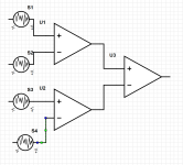
So U1 will detect whether S1 is greater than S2. U2 will detect whether S3 is greater than S4. What does U3 do?
Is this what you're trying to implement:
OUT = if(S1 > S2) OR if(S3 > S4)
Can you write out a regular expression for what you want the output to do? What you've drawn has the output undefined if S1 < S2 and S3 < S4. The output is also undefined if S1 > S2 and S3 > S4.
Tom
Is this what you're trying to implement:
OUT = if(S1 > S2) OR if(S3 > S4)
Can you write out a regular expression for what you want the output to do? What you've drawn has the output undefined if S1 < S2 and S3 < S4. The output is also undefined if S1 > S2 and S3 > S4.
Tom
Ah ok so some context:
I'm working on an analog preamp for a project (order the board, solder on the components, etc.). One thing I wanted to include was some sort of feedback/feedforward circuit. The feedback would be from the speakers themselves and then reinserted into the filter (stepped down to the same relative gain as the filter section of the preamp). What i would be comparing is the signal from the speaker to the signal in the filter, and then, comparing the signal to the other signal in a differential circuit. Hope that clears some things up 🙂
BK
A differential amplifier would do the job.
Same inputs and nothing out.
Different inputs and difference between signals out.

Same inputs and nothing out.
Different inputs and difference between signals out.
Sounds to me like you want a DC detector or juist detecting differences (distortion ?) between analog preamp output and the speaker output. Totally doable with simple components . I made this for my HPamp , it works well depending on how small you want the detected differences. As an example :Ah ok so some context:
I'm working on an analog preamp for a project (order the board, solder on the components, etc.). One thing I wanted to include was some sort of feedback/feedforward circuit. The feedback would be from the speakers themselves and then reinserted into the filter (stepped down to the same relative gain as the filter section of the preamp). What i would be comparing is the signal from the speaker to the signal in the filter, and then, comparing the signal to the other signal in a differential circuit. Hope that clears some things up 🙂
BK
Update:
Did a little reading about analog multipliers and dividers. The key take away is not the intended one, but enough for me in the context of this build: holy crap they're expensive! Lol I may as well just use 3 comparators and call it a day! Thank you to everyone who humored my curiosity 🙂
Did a little reading about analog multipliers and dividers. The key take away is not the intended one, but enough for me in the context of this build: holy crap they're expensive! Lol I may as well just use 3 comparators and call it a day! Thank you to everyone who humored my curiosity 🙂
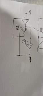
@tomchr so fiddled around with it and this is more accurate to what I want to do. It's going to be one side of a differential amplifier circuit so the other side will be the same. Not sure if I should do it differential as well. (Sorry about quality it's a doodle while I was on break lol)
Attachments
I still can't wrap my head around what you're trying to accomplish so it's difficult to provide help. Are you just going to compare the signals to see if one is larger in magnitude than the other? Or will you need to compute the difference between them?
Tom
Tom
I go a little overboard with adding extra diodes to protect inputs . Always try to forsee situations where with a power failure or other mishap , the IC's don't get destroyed. For me here , it is signals in the 10's of mV and higher , so added noise of diodes has no impact. If you want to detect differences of < 1 mV it could have an impact on accuracy , but these small signal , low leakage diodes are pretty good.@RickTH that looks great! Definitely gives me an idea of what I want to do. My only question would be: wouldn't you get noise from the diodes?
Always better to over engineer than under engineer 😉I go a little overboard with adding extra diodes to protect inputs .
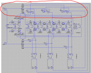
So this is still a work in progress (getting the ideas out of your head and on to paper so to speak) so part selection isn't there yet (and also super simplified because not everything is down on paper yet). The idea is to push the signal back to as close as source as possible. The assumption here is that source is your highest quality signal. After coming off the speaker output I wanted to loop it back around and compare the signals from the speakers and the filter, create an error signal from the difference between them, and then loop it back around to the signal source, thereby completing the feedback loop. I was intending to do the same comparison from filter to source, hence the adders above and below. My thing was I just noticed how many op amps I was using and was thinking to myself "that's a lot of op amps" so I was wondering if there's a way to do what I had in mind with less parts. It's looking like that may not be the case and I may just have to bite the bullet.I still can't wrap my head around what you're trying to accomplish so it's difficult to provide help.
Attachments
Ah. You want the signal at the speaker terminals to be as close to A*V(in) as possible. Novel concept.... 😉
What you're looking for is remote sensing. It's common in lab power supplies so you can probably find inspiration there. All you need to do is to move the feedback take-off point to the speaker terminals instead of having it within the power amp. Now, the issue with that is if that wire ever fails or loses its connection the amp will lose its mind. So I would connect the original sense node internally in the amp with something like 10 Ω. Then make the sense connection to the speaker. As long as the resistance of the sense wire is much lower than that 10 Ω that connection will 'win'.
Tom
Sooooo I haven't started the power amp section yet technically so definitely something I can keep in mind lol. I'm still trying to decide whether I want to use an eval board, or make it from scratch. I can have more granular control if I make it myself, but that's also either A) a larger board or B) another board I would need to make altogether. That being said, if I make it myself, that also means I can mess around with the output circuit as well to maybe make it more coherent with the preamp.All you need to do is to move the feedback take-off point to the speaker terminals instead of having it within the power amp
- Home
- Design & Build
- Parts
- Multiple Analog Comparator


