I am not sure if this is the correct forum / place to ask this question. If not, mods, please move.
I am just now starting to get my feet under me when it comes to understanding some facets of even the most basic measurements, how to do them properly / consistently, and most importantly how to understand and apply what I see in all the pretty, pretty, pretty charts and graphs.
I ran into something this morning that I haven't seen before, and it fascinated me. I was measuring my first "real" amplifier that I got back from a friend recently. It carries a lot of nostalgic value to me. So, I was going to put to use all my new and wonderful DIY knowledge, clean it up and possibly give it a refurbish. I am reluctant to even recap a commercial amp, so I wanted see how it was currently performing. Overall it seems fine. 0.00 VDC offset, stable for 24 hours, and basic performance measures seem in-line with expectations.
But...
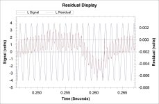
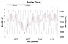
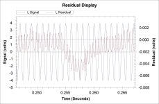
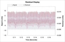
Here are a few plots of the distortion residual. The reason they're not really tight across just a few waves is that when I was watching it "zoomed out", it was clearly varying in a pattern over time, while the signal remained stable. The software sets the scale for the residual vs. signal automatically. So, the residual isn't varying dramatically (relatively speaking) over time, but it does "swing up and down" in a pattern.
In all the vastness of experience (HA!) I have measuring 6 or 7 other things around the house for fun, I haven't seen this before. All the other amps are FW clones, a BA-3 variant, and my Sony VFet. For all those amplifiers, the voltage of the distortion stayed 'flat' for lack of a better description vs. the average across a few ms wandering up and down. I wish I could describe it in more accurate terms. I can take a video also if it helps. This amp may have a servo. I am wondering if this type of behavior is associated with a servo correcting for offset... (The amp is an Aragon 2004 from circa 1995).
Why do I care and ask? I'm curious, and I haven't seen this before. We tend to look at "static" images of the residual and/or the FFT. Since I typically go with the idea that what we distinguish in amplifiers is mostly due to the distortion (all other things remaining equal)... I was wondering if I was off my rocker. If we accept or consider that a few mV of distortion with a certain pattern against a much larger signal affects our perception of the sonics of an amplifier... I am wondering if the distortion profile "wandering" up and down is normal for some amplifiers and its potential effect.
Listening tests with my ears likely won't reveal too much, but I've become fascinated with "what the distortion looks like" in a manner of speaking. Possibly a rabbit hole not worth diving into, but ...
Thanks in advance for any insight and ideas for how to understand what's happening and why...
Cheers,
Patrick
Attachments
Last edited:
Thank you for the quick response. It's still hooked up to the analyzer, and I'm happy to measure some things, but please forgive my ignorance on the topic.
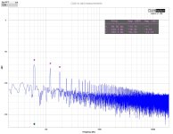
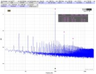
Are you asking for what the noise floor looks like? There's not a clear residual for that. Here is the FFT. The analyzer and a scope will clearly pick up the 60Hz mains and harmonics. Is that what you're asking? Mainly I want to try and answer your question as clearly as I can.
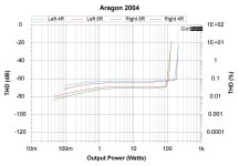
Apologies, I can't title each graph for the residual. Thank you for asking. Those were taken at 1W @ 8R => Signal 4Vp. Not close to clipping. I haven't measured the clipping voltage dead on yet, but it measures (relatively) flat in THD out to its 100W 8R rating.
Attachments
WAIT! I think you were trying to give me a clue.
Doing some back of the matchbook math... and taking a closer look at the plots....
Roughly... 8:1 ratio of the periodicity of the signal to the larger wave of the residual... 1000/8 => 125.
Is it a possibility / likelihood that since the actual harmonic distortion of the 1kHz signal is comparatively low, and the instrument sensitive enough, that I am seeing the effect of the mains harmonics in the residual plot?!
If so, thank you for the hint and making me think for myself. If not... I'll keep noodling.
Attachments
Ran one more check... I think it is what you were trying to clue me into...
I upped the signal and zoomed out a bit more. I happened to do it while I was checking the performance at 4R.
A (roughly) 16:1 count seems easier than trying to determine the exact periodicity of the waveform...
So... it would seem that the distortion (and who knows, possibly the signal too, but the scale won't let me see it) signal rides along on the 60Hz mains frequency and harmonics.
NEAT! (If I got it right)...
Last question, if I figured it out...
Is this because it's a (relatively speaking) low bias class A/B amplifier vs. the other types of amplifiers I've been noodling with => so, the power supply ripple has a larger effect?
Anyway... thank you to @MarcelvdG for possibly pointing me toward something more to investigate.
I'd still love to know if I'm heading in the right direction ... 🙂
Thanks!
Patrick
Attachments
when you have so high content of drek on left side, think of limiting/cutting that part of spectrum from test
I mean, just for testing sake
logical is to think how to cure that, but sometimes you can't do that with commercial products
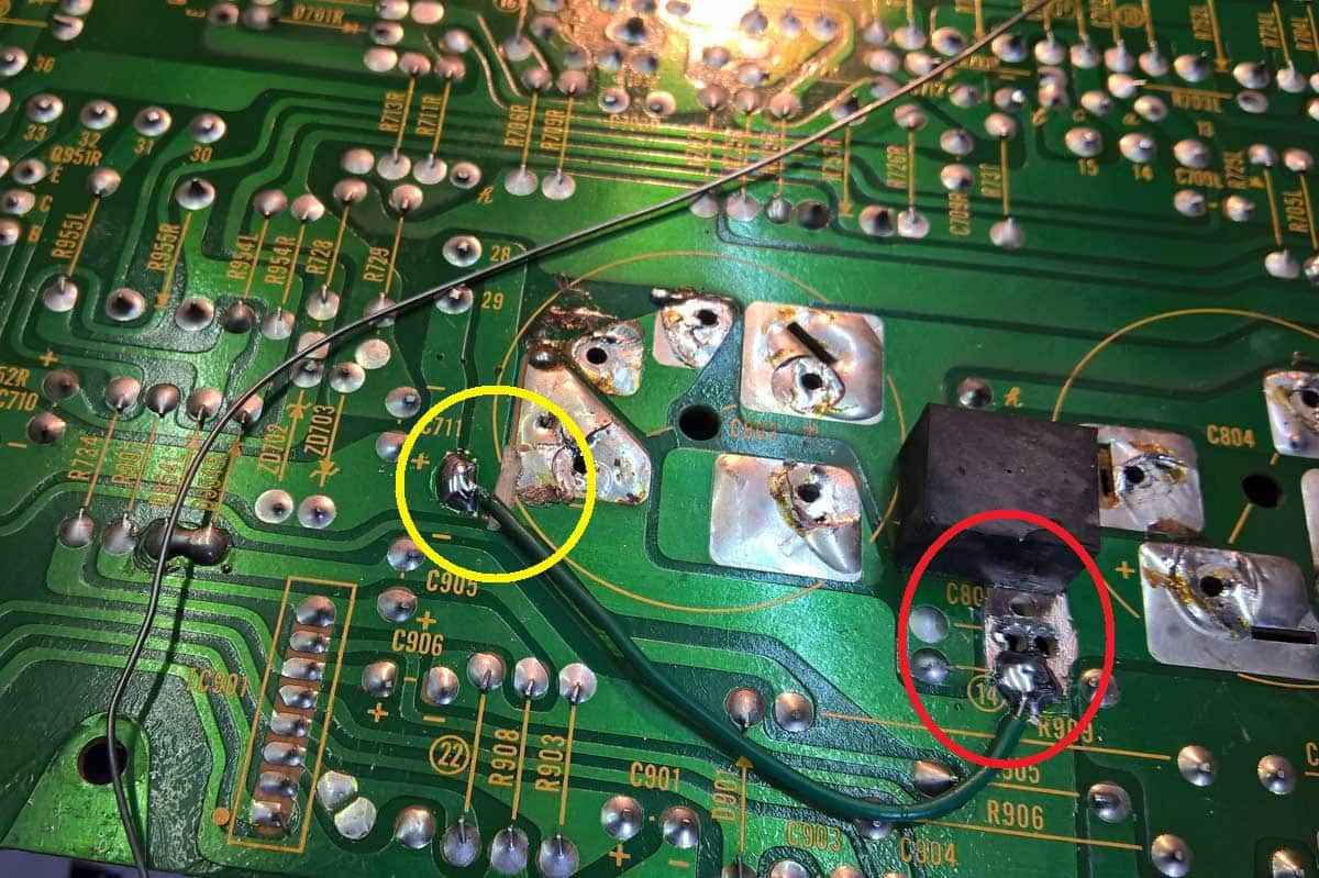
funny stories mode - rearranging GND routing on pcb of venerable Hitachi amp
https://www.zenmod.in.rs/hitachi-hma6500-little-mosfet-amp-from-yore-resurrection-by-zm/
I mean, just for testing sake
logical is to think how to cure that, but sometimes you can't do that with commercial products
funny stories mode - rearranging GND routing on pcb of venerable Hitachi amp
https://www.zenmod.in.rs/hitachi-hma6500-little-mosfet-amp-from-yore-resurrection-by-zm/

^ Thanks!
I'm just happy that I saw something and was able to (I think) determine what I was looking at. As you've had direct experience with me, you know sometimes I don't see the forest for the trees.
Now that I know what it is... I do begin to wonder... which sometimes can be a bad thing...
Not telling you anything new, but these are things I'm just starting to realize. I still may have 90% of this wrong, but it's fun.
Anyway... lots more to learn. I think I have just seen a visual manifestation of PSRR (or lack thereof), but ... still more to read and learn.
I'm just happy that I saw something and was able to (I think) determine what I was looking at. As you've had direct experience with me, you know sometimes I don't see the forest for the trees.
Now that I know what it is... I do begin to wonder... which sometimes can be a bad thing...
- How can I get my hands on some notch filters... I'm using a filter specifically for another thing that I was given, and that's still driving me batty trying to discern what I'm seeing with and without it in place. Adding more toys to the box is fun, but I haven't learned to use what I have.
- We care about 20Hz to 20kHz generally speaking... if the "noise floor" of the PSU at 60Hz and harmonics is higher than the actual harmonic distortion of the amp, does blue smell like the #2.
 I may run some signals at 60Hz just to see what I see.
Not telling you anything new, but these are things I'm just starting to realize. I still may have 90% of this wrong, but it's fun.
Anyway... lots more to learn. I think I have just seen a visual manifestation of PSRR (or lack thereof), but ... still more to read and learn.
@ItsAllInMyHead I hadn't a clue it was severely distorted mains hum, you are the one who figured that out. It just looked like something added to the distortion residue to me, hence the question what it looks like without signal.
You interpreted it as time-dependent distortion. The only thing I could think of that would cause that was supply variations, and those should have the biggest impact close to or in clipping. Hence the second question.
You interpreted it as time-dependent distortion. The only thing I could think of that would cause that was supply variations, and those should have the biggest impact close to or in clipping. Hence the second question.
simple as this - if having so high content on left side, which is (supposedly) influencing measurements big time, you have only two options :
- make that PSU better, or
- abandon measurements
as we all know (sort of), scientific praxis is teaching that both positive and negative results are equally contributing
but, somehow with getting in Geezer category, I'm more and more favoring positive ones - confirmatory that I did something in proper way thus resulting in direction I'm expecting
playing with drek commercial gadgets slowly but surely got to "do not touch, you did already enough of that in 30 or so years of service work" category
OK, learning is good, learning is a must, but I'm old enough to choose what I'm learning of

By the way, I agree with what Zen Mod implied in post #6, namely that it is likely to be a silly ground connection or some other layout imperfection causing crosstalk from the power supply charging current peaks to the signal path. That would explain the waveform of the mains hum in post #1 and the huge number of intermodulation peaks in post #4.
To both - Got caught mid-typing with latest post from MarcelvdG.
Start with technical fun... that also explains (possibly) why the channel (left) physically closest to the PSU wiring and the donut has slightly poorer performance. See attached. I've been having fun.
I completely understand (now) and agree with you both. The amplifier is "as-is", it operates as a unit. So, I measured how it behaves in its entirety.
For me, part of the magic is the childlike wonder of discovery. I suppose part of the statement "ignorance is bliss" is true. It sure is fun learning something, even if it's already known.
I'm already noodling though how I could use my new PSU with it and/or just possibly improve the existing one. It has no CRC or anything, just 4 caps. I would not have the slightest idea how to begin re: looking at the overall layout / grounding scheme. I'm also completely unfamiliar with the requirements for a Class A/B amp PSU vs. what I've been building. I haven't measured the rails and checked for a schematic, but it seems likely I can get away with it. My guess is ~42VDC loaded. However, it's possibly a little more complex than I'd like. There are a few "auxiliary" circuits. One idea is to use my "quiet" external PSU for the signal and leave the existing donut and other wiring for the other circuits. Possibly overkill, but it's DIY. Whatever I do, I'd like for it to be "reversible". I may do nothing. Dunno. It would be wonderful to pull a little Eliza Doolittle action on the old girl.
From a measurement standpoint today, it is what it is. I doubt I'll go deeper. It's really no worse from a practical standpoint than many I've seen (online). I found some other measurements online, and mine are in-line with what they saw from a PSU noise standpoint and a few other things. So, at least they may be relatively consistent. It seems characteristic of "vintage" amplifiers of this type.
More importantly, I hooked it up to some speakers... There was some (obvious) PSU hum, but even if nostalgia / sentiment has taken over... it sounds quite pleasant. Once I get the Vandersteens back up and going, they'll be friends reunited. Then I can think back to when I was 25 years younger...
I truly appreciate the insights. If there's anyone out there that has some ideas for mods ... I'm all ears.

Edited for a typo and some clarity around the existing PSU filtering.
Start with technical fun... that also explains (possibly) why the channel (left) physically closest to the PSU wiring and the donut has slightly poorer performance. See attached. I've been having fun.
I completely understand (now) and agree with you both. The amplifier is "as-is", it operates as a unit. So, I measured how it behaves in its entirety.
For me, part of the magic is the childlike wonder of discovery. I suppose part of the statement "ignorance is bliss" is true. It sure is fun learning something, even if it's already known.
I'm already noodling though how I could use my new PSU with it and/or just possibly improve the existing one. It has no CRC or anything, just 4 caps. I would not have the slightest idea how to begin re: looking at the overall layout / grounding scheme. I'm also completely unfamiliar with the requirements for a Class A/B amp PSU vs. what I've been building. I haven't measured the rails and checked for a schematic, but it seems likely I can get away with it. My guess is ~42VDC loaded. However, it's possibly a little more complex than I'd like. There are a few "auxiliary" circuits. One idea is to use my "quiet" external PSU for the signal and leave the existing donut and other wiring for the other circuits. Possibly overkill, but it's DIY. Whatever I do, I'd like for it to be "reversible". I may do nothing. Dunno. It would be wonderful to pull a little Eliza Doolittle action on the old girl.
From a measurement standpoint today, it is what it is. I doubt I'll go deeper. It's really no worse from a practical standpoint than many I've seen (online). I found some other measurements online, and mine are in-line with what they saw from a PSU noise standpoint and a few other things. So, at least they may be relatively consistent. It seems characteristic of "vintage" amplifiers of this type.
More importantly, I hooked it up to some speakers... There was some (obvious) PSU hum, but even if nostalgia / sentiment has taken over... it sounds quite pleasant. Once I get the Vandersteens back up and going, they'll be friends reunited. Then I can think back to when I was 25 years younger...
I truly appreciate the insights. If there's anyone out there that has some ideas for mods ... I'm all ears.

Edited for a typo and some clarity around the existing PSU filtering.
Attachments
Last edited:
Normally there are some pretty big charging current peaks flowing from the secondary side of the power supply transformer through the rectifier diodes to the supply reservoir capacitors and back to the secondary of the transformer. To prevent hum and intermodulation with mains hum, you want to make sure that the wires that carry those current peaks are separated from the signal ground wiring. The link Zen Mod put in post #6 shows an example how not to do it and how to improve it.
Thank you! That's encouraging. I have been trying to review the board layouts along with sketching up a schematic. It's a good exercise for me to learn. It's interesting timing b/c it was only recently that several people helped me build an external PSU. It does what it does remarkably well, IMO, but I had great coaches.
One of the things that has fascinated me is how the layout of the boards and/or wiring can affect things 'dramatically' even when built to the same schematic. I haven't 'learned' it yet, but I've got some examples of what do do and what not to do. There are also a few examples of things people have done with the filter / rectification boards from the store that seem to be along the same lines.
It will be a slow one for me. However, if (when) I figure out a few key aspects, I might remove the existing PSU filter and add in different boards altogether. Then, if I desire, I can return it to "stock". Since, relatively speaking, filter boards are also somewhat simple in KiCad and other software, it might be a good opportunity to dip my toes into that water. The classes may finally go to real use.
Another option is to use my external PSU, but I'm still working out whether that's really practical.
The options are limitless, but my brain power is ... limited. 🙂
Thank you again!
Hi Patrick, do you have your QA connected to a desktop PC (plugged into the wall) or do you run off a laptop (ideally running on battery power)? The desk that I have all my equipment for building and where my main PC is, also happens to be quite an electrically noisy environment for measurements, especially for mains (60/120/180) frequency and I have just learned to ignore it for now as it's not that excessive. I do have a laptop and battery pack to run 'better' measurements from but so far, I've been too lazy to haul a heavy amp to a nice quiet corner of the house, although I do plan on doing that in the future.
I should also add that most of my measurements are being done on amps as I build them and powered from lab supplies, rather than completed amps. That's another reason why I continue to do my measurements where I do. The lab supply isn't the cause of my mains noise and I think it's possibly from the PC or from the walwart for my powered USB hub.
I should also add that most of my measurements are being done on amps as I build them and powered from lab supplies, rather than completed amps. That's another reason why I continue to do my measurements where I do. The lab supply isn't the cause of my mains noise and I think it's possibly from the PC or from the walwart for my powered USB hub.
Last edited:
Hi Twitchie -
Great question! All measurements are done with the QA and laptop not connected to mains.
The QA is connected to the laptop via USB for power and data. The laptop is running off of battery. The laptop charger is not connected to the laptop during measurements.
FWIW, the laptop (and/or the QA) seem to have nice mains noise isolation. I ran some back-to-back loopback (say that a few times fast) with various supply configurations. QA connected to powered USB hub etc. like on the QA site. Since my laptop has enough juice (and I use a short / 24AWG USB cable, I connect directly. I found that there were no meaningful differences in the various configurations, but my laptop battery lasts long enough. So, I went with what I think is the 'safest' route to ensure that nothing but the DUT has a mains connection during measurements.
Thanks for asking.
Note - You didn't ask, but... For any critical measurements I connect the DUT to my 'audio' mains. It's a separate breaker from everything else, and I unplug everything else from that circuit. I did a very quick and dirty check to see if more accessible outlets produced any more or less 'mains noise' than the one I actually use for my system. The answer was... they are not any different using my crude measurement techniques. With that said, I try to minimize variables when I think it's important. So, I clear off a chunk of the rack when I feel the urge. One of the things I want to check when I get more of that precious, precious time is what folks mean by other gear dirtying up the mains. I want to see what I measure with a big nasty fluorescent ballast, some routers, and a few other things on that circuit. I'm not sure what I'll see, but I'm a curious guy. Also, I can't remember what amplifier I was building, but when I had it on my bench (separate supply from the audio supply) I had a TERRIBLE hum. Someone walked me through troubleshooting, and it turns out that it was caused by my florescent magnifying ring lamp. 🤷♂️
Either way... fun, fun stuff!

Edited for my typical transposition of words / letters when typing quickly... and for clarity around connections.
Great question! All measurements are done with the QA and laptop not connected to mains.
The QA is connected to the laptop via USB for power and data. The laptop is running off of battery. The laptop charger is not connected to the laptop during measurements.
FWIW, the laptop (and/or the QA) seem to have nice mains noise isolation. I ran some back-to-back loopback (say that a few times fast) with various supply configurations. QA connected to powered USB hub etc. like on the QA site. Since my laptop has enough juice (and I use a short / 24AWG USB cable, I connect directly. I found that there were no meaningful differences in the various configurations, but my laptop battery lasts long enough. So, I went with what I think is the 'safest' route to ensure that nothing but the DUT has a mains connection during measurements.
Thanks for asking.
Note - You didn't ask, but... For any critical measurements I connect the DUT to my 'audio' mains. It's a separate breaker from everything else, and I unplug everything else from that circuit. I did a very quick and dirty check to see if more accessible outlets produced any more or less 'mains noise' than the one I actually use for my system. The answer was... they are not any different using my crude measurement techniques. With that said, I try to minimize variables when I think it's important. So, I clear off a chunk of the rack when I feel the urge. One of the things I want to check when I get more of that precious, precious time is what folks mean by other gear dirtying up the mains. I want to see what I measure with a big nasty fluorescent ballast, some routers, and a few other things on that circuit. I'm not sure what I'll see, but I'm a curious guy. Also, I can't remember what amplifier I was building, but when I had it on my bench (separate supply from the audio supply) I had a TERRIBLE hum. Someone walked me through troubleshooting, and it turns out that it was caused by my florescent magnifying ring lamp. 🤷♂️
Either way... fun, fun stuff!

Edited for my typical transposition of words / letters when typing quickly... and for clarity around connections.
I’m proud to say that I actually understand what you’re saying here.Is it a possibility / likelihood that since the actual harmonic distortion of the 1kHz signal is comparatively low, and the instrument sensitive enough, that I am seeing the effect of the mains harmonics in the residual plot?!
That is all.
- Home
- Amplifiers
- Pass Labs
- "Wandering" Distortion?
