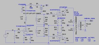
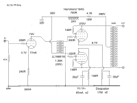
I'm just in the middle of this project, so this is a provisional schematic. I've done the output stage so far, which is as the schematic.
Input stage will be 6V6 in triode or 6AH4, whichever sounds better. Other tubes are possible, e.g. EL33 in triode. Needs a mu of around 8 or over. I originally planned a 2P29L or 112A input but ran out of room in the chassis.
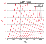
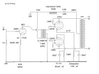
The EL12n is an 18W dissipation tube with a mu of 18 in triode. The bias is low at around 10V so I used separate cathode resistors as suggested in the data. I don't know if 150R needs a cathode bypass but I've put in a DC Link one.
I was thinking 4V bias on the input tube to use a 220R resistor and avoid a bypass cap. This might be up for discussion.
Any suggestions and improvements very welcome.


Looks Great!
You might want to bypass the input tube's self bias resistor.
That makes the input stage's rp lower, more able to drive the interstage's inductance at low frequencies.
The 30uF bypass caps might have to be increased.
The real factor includes the Effective cathode impedance: (1/Gm) + (plate' RL/u). All that is in parallel with 150 Ohms.
Do not only bypass the 150 Ohms, also bypass the active cathode impedance that is in parallel with the 150 Ohms.
Let us know your progress!
Last edited:
I plan something similar for 6V6 (6p6s) PP but with Hammond 124B. But I have also many EL12 too... what do you think about EF6 (?) - 124B - EL12 PP?
Andy,
As 6A3sUMMER wrote (and during our conversation I also suggest), the 30uF isn't enough for EL12. You will lose all bass.
The simulation suggest at least 180-220uF.
If you choose it, the first stage cathode blocking isn't so important. Try it with blocking capacitor or without it.
If you use such low B+ (instead of for example 350V), the power would be half of the theoretical maximum.
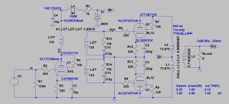

Hello Bela. Good suggestions. Unfortunately I don't have room in the chassis for any meaningful modifications, so the B+ stays around 280v.
The EL12n will indeed take a much higher voltage, but it's rated for 18W and I'm not far off that with 65mA per tube. Not sure what to do about the cathode bypasses on the EL12ns. I like using DC Link caps and there isn't room for much over 40uF. I'll have to listen and see what gives. Electrolytics would take up less room but I'll try the DC Links first.
I'm going to start with the 6AH4 since I have 3 of them. I could get more from the USA if necessary.
Another warning: if you have 18mA IT, be sure, that the anode AND the 2nd. grid current sum don't exceed it.
Thanks Bela. That would indeed be the case with a 6V6. but I'll start with the 6AH4.
If it sounds nice I'll leave it in. My guess, based on using it in the past, is it will sound better than 6V6 in triode. It comfortably outclassed a 1626, a 6CK4 and other similar tubes.
If it sounds nice I'll leave it in. My guess, based on using it in the past, is it will sound better than 6V6 in triode. It comfortably outclassed a 1626, a 6CK4 and other similar tubes.
Andy - another tube you might consider for this project is EL38. 25W plate + 8W screen dissipation, amplification factor 16.5.
From datasheet LL1660/10mA primary inductance is 42H
LL1660/18mA approximately prorates to 20H.
6AH4 plate resistance is 1800 Ohm.
Are these the limiting factors for low frequency response ?
LL1660/18mA approximately prorates to 20H.
6AH4 plate resistance is 1800 Ohm.
Are these the limiting factors for low frequency response ?
20H represents about 2k5 impedance at 20Hz (Z=2*Pi*f*L).
42H about 5k3.
Rule of the thumb of load: at least 2, rather 3 times more load requiring than tube plate resistance.
If is not fulfilled, the distortion growing, the output swing decreasing in this range.
BTW LL1660 in "Alt V" configuration (SE to PP) has 42H primary inductance and max. primary current (up to 0.9T) is 18mA.
Andy - another tube you might consider for this project is EL38. 25W plate + 8W screen dissipation, amplification factor 16.5.
Good call. I actually prefer the EL38 to the EL12n and I have some nice ones. However this is for a friend who's not too familiar with tubes. The EL38 has a top cap with the anode voltage on it, so for safety reasons it would have to be enclosed and that's not easy to do on this particular chassis.
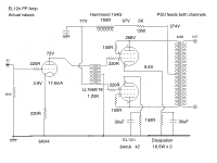
Here's the input stage with 6AH4, again a provisional circuit. Building it now. The operating point would change if I used a bypass cap.
Yes - PSU is always for both channels. I should have marked that. Hope to have sound today.......
Would you try a couple of LEDs for the input stage biasing? 4.1V is a goid match for a couple of LEDs. Interested to hear your opinion about the difference vs a resistor or r+c.
I've tried LEDs in the past and moved on - can't remember why. Same with battery bias. Didn't like SIC diodes either.
I tend to end up with resistors - they are a pretty pure sound without obvious artifacts.
I tend to end up with resistors - they are a pretty pure sound without obvious artifacts.
Well, it's up and running. Good news is that it sounds very nice - I like it. It's for a friend but I wouldn't mind keeping it myself. I've been using SE DHT amps for years, and this is all indirectly heated and push pull. Quite a change - it surprises me that the sound is so good. The EL12n and the 6AH4 are both good valves and the LL1660/18 seems to work OK as a phase splitter. So my instinct that this would be a good combination seems to have worked. I also prefer 2 stage amps.
Only downside is it hums - needs more capacitance in the PSU for a start. It's also a bit heavy, so I think I'll put the PSU in a separate chassis. That will make a better layout easier to achieve with more space.
Only downside is it hums - needs more capacitance in the PSU for a start. It's also a bit heavy, so I think I'll put the PSU in a separate chassis. That will make a better layout easier to achieve with more space.

Fair enough. Never tried myself, will definitely have a go to see whether I notice any difference.I've tried LEDs in the past and moved on - can't remember why. Same with battery bias. Didn't like SIC diodes either.
I tend to end up with resistors - they are a pretty pure sound without obvious artifacts.
A nice way to do AB testing is to start with 2 mono-blocks, or a Stereo amplifier:
Modify one channel to be different (LED instead of resistor, etc.).
Then build a switch box that does the following:
1. Takes the Left channel output from a CD player, switches and sends it to the Left channel amp, and then to the Right channel amp.
2. The other part of the switch, connects the loudspeaker to Left channel amp output, and then to the Right channel amp output.
Just a fun and easy way to test LED versus resistor, X versus Y, Capacitor versus Capacitor, KT77 versus EL34, etc.
- Home
- Amplifiers
- Tubes / Valves
- EL12n Push Pull amplifier
