FS: Ncore amplifier

I have 2 amps for sale.

1. NC400 +SMPS monoblock pair. Asking 800usd include ship and paypal

2. NC502mp pair in single metal chasis - Asking 825usd include ship and paypal

interested please PM me. Ship from S.E Asia

Attachments

  • 1605878790925.jpg
    1605878790925.jpg
    419.6 KB · Views: 553
  • 502mp.jpg
    502mp.jpg
    88.2 KB · Views: 581
  • Hypex Nc400_1.jpg
    Hypex Nc400_1.jpg
    149.2 KB · Views: 552
  • Hypex Nc400_2.jpg
    Hypex Nc400_2.jpg
    161.4 KB · Views: 551

Design Idea: Auto double track pre-amp circuit

Hello ..

I was modifying a karaoke pcb, in attempt to fix microphonics , when part of pcb was touched/tapped it produced sound in speakers, this circuit used JRC 4580 op-amp and PT2339 for echo.
when reading PT2339 datasheet got this idea to add circuit for Auto double track (sound like two people singing). Searched internet found some article on phase shifter.
My question is it practical to use op-amp phase shifter to achive Audo double track effect, if some had tried please share your points.

Thank You

[Hypex NCore] NC502MP 2x350W / 8R module to sell + cable set.

Hi,

Following the abandonment of my project. I am selling one brand new NC502MP with a cable kit.

Perfect module for any DIY project.
Can drive any sensitive speakers.

Safe value for diyer )

Like new !
free shipment to Europe only.
Paypal Please.

Price : 440€ + cable set + free shipment


SPEC :


Power max. 2x350W @ 8Ω
2x500W @ 4Ω
2x450W @ 2Ω
Support full balanced inputs
THD+N 0.0018%
SNR 124dB
Noise output : 47µV
Output impedance : 1.5mΩ
Reponse : 10Hz - 48kHz
max senstivity à 2.35V RMS
XLR : 2x1.17V RMS
RCA : 2.35V RMS
Efficiency 92%


Distortion hum -Line input preamp JRC4580

Hello,

Modified Karaoke microhone bass/treble input stage for removing microphonic effect on original PCB.

Issue was around Bass Treble and Echo mixer circuit. removed op-amp and related components for bass treble, replaced with circuit made on veroboard.
Schematic based on jrc4558 preamplifier circuit published in componentsinfo (Not posting URL)
opsting original schematic and modified one. (water mark is there in image).
Modified values (based on articles online) maked in red.

Tried both Inverting and on-inverting circuit, Inverting op-amp circuit has more distortion , hum noise when connected, this does not happen with Non-Inverted op-amp circuit.

Imput 1 and 2 is from another op-amp from microhphone UHF receiver circuit.

Modification removed microphonic effect.

Issue faced: when one of the mic (single mic) is used it works good, turned mic volume pot full, no distorsion.
Switched on scond mic, turn voume up, whem more than half way hum starts increases in volume by itself, when second mic volume turned down it goes off.
accidentally touched preamp resistor on pin 2 / 6 reduces this hum sound (there is other distorsion due to touching).

will it help if 33pf capacitor is connected in parrallel across 100K (feedback) ?

Requesting help to make circuit stable when using both mics.

Original Schematic:
jrc4558-preamplifier-circuit.gif


Modified schematic:: Used RJC4580, two

jrc4558-mod-preamp-circuit.jpg


Thank You

NAIM Audio NAIT 5si (not 5i) Integrated Amplifier - Schematic wanted

This amp from a friend sounds good - go to
https://www.stereophile.com/content/naim-audio-nait-5si-integrated-amplifier-measurements
But sometimes (not often) right channel sounds with heavy reduced level and increased distortion on all inputs (unfortunately not sensitive to vibration and temperature variation).

PCB is mainly equipped with SMD parts (except power devices, the big BHC elcaps behind the rectifiers and any few others).
Without circuit diagram troubleshooting is too difficult and sending to Naim Audio will be very expensive due replace the complete main board there.

Who can upload the schematics ?
Thanks for your effort.

P.S.: this thread don't provide the wanted information:
https://www.diyaudio.com/community/threads/naim-nait-5i.322055/

Attachments

  • hfm11_3002.jpg
    hfm11_3002.jpg
    81.1 KB · Views: 322
  • hfm11_3001.jpg
    hfm11_3001.jpg
    84.1 KB · Views: 402
  • naim-nait-5si_inside_1_.jpg
    naim-nait-5si_inside_1_.jpg
    240.7 KB · Views: 408
  • hfm11_3006.jpg
    hfm11_3006.jpg
    138.9 KB · Views: 439
  • Naim_NAIT_5SI_integralt_erosito_4.jpg
    Naim_NAIT_5SI_integralt_erosito_4.jpg
    135.2 KB · Views: 386
  • post-1956-0-26179900-1511373251 (1).jpg
    post-1956-0-26179900-1511373251 (1).jpg
    133.3 KB · Views: 1,012
  • 25725-max_naim_nait_5si_3.jpg
    25725-max_naim_nait_5si_3.jpg
    101.6 KB · Views: 470
  • 1014NAITfig08.jpg
    1014NAITfig08.jpg
    27.2 KB · Views: 372

July 2023 Store Update

You may have noticed the diyAudio store has got a bit of a facelift today.

We've been busy over the last few months upgrading and modernizing almost every system that the store uses, in order to provide you with a better experience, more affordable shipping options and better communications.

All customers

USA customers

  • Our UPS rates have improved.

International customers

What's coming next?​

The biggest changes we've made are in our back-end systems (those you cannot see). What these changes will allow us to do is to improve the store much more easily as time goes on, unencumbered by legacy systems.

Thank you very much for your support.

If you have any questions or see any bugs, problems, or something looks like it is out of place, please contact the helpdesk at contact@diyaudiostore.com or post in this thread for general discussion.

MB Quart 95-6383 spec?

I bough some cheap custom speaker with mb quart 95-6383 and would like to have speak on those tweeter. They play very loud and clear but they are too loud vs the midrange speaker.

they are paired with 10 inches woofer from addison and the only cross over in a simple capacitor on the tweeter.

i guess one solution to hear the woofer a little more and see if there is something to do with those speaker would be to add l-pad to the tweeter?

Curcio CD12V DAC, info and help sought

Hey all,

Looking for documentation for the Curcio CD12V dac. Hopefully somebody has held on to it and can share. I've reached out to Joe Curcio without success.

Background: I have a working CD12V that I picked up at an Estate Sale. Didn't know what it was until I got it home. The DAC has been working and in use intermittently without significant issues since.

You can read about the score here:
DIY tube pre-amp(s) identification help needed | Audiokarma Home Audio Stereo Discussion Forums

The reason I want to locate the original documentation is because I would like sort out a couple things on the unit.

  1. There are 3 LED's on the front panel, one is obviously power, another illuminates upon "Lock" with the CD player, but the 3rd LED never illuminates. I cannot for the life of me figure out what it is for. Maybe for 48khz instead of 44.1khz? Or is it a non-functioning MUTE circuit?
  2. If it's possible to reduce the gain or output level?
  3. Maybe adding a Mute switch? It seems like I've seen that option on the few examples seen on the web. When the unit is powered up, but when there is no lock on a digital signal there is some annoying noise that will come through the system.
  4. I also want to explore adding multiple inputs. I know this won't be reflected in the documentation. I will probably look for an off the shelf DIY kit (i.e., Twisted Pear Audio) and will need to identify a place to tap power for whichever kit I locate.


Maybe y'all can help me solve the gain issue without the documentation. Curcio lists the output level as 4.4v RMS on his website. He also posts the attached schematic. I've circled R121 and R122, which look to me like they may be a voltage divider (?) and a good place to adjust the output level?

R121 and R122 appear to be 470Ω and 3.3M based on visual inspection of band codes. They are just before "LO" which I believe stands for "Line Out"?

I'm guessing the simplest solution would be to add a pot on the analog output of the DAC. But, if I can simply change out these resistors I would think that would be better than adding another component. I would really like to get the DAC output down to something like 1.5 - 2.2v output to gain match with the rest of the components in my system.

Any other suggestions? This unit is set up for 12AT7's, not 6DJ8's. Is there a 12AT7 substitute with less gain? Is there a way to adjust gain in the circuit closer to the tubes? Like in a feedback loop?

I have the most basic understanding of tube circuits and can read a schematic OK. But, figuring this out is a little over my head and need some hand-holding.

Thanks in advance!

Attachments

  • CD12V schem..png
    CD12V schem..png
    189.8 KB · Views: 617

tube preamp transformer questions

Hi all I could use some expert advice,

Does anyone have some advice on the following? I am making a tube preamp on basis of a CAT SL-1 PCB I got somewhere (I am a noob who is still learning so I use other peoples pcb's for my builds atm), according to text on the pcb it requires two secondaries:
- 250VAC 80mA
- 6.3VAC 3A

These are the tubes this preamp uses:
1x ECC82
2x ECC83
1x ECC88

Can I use the following toroid?
- 250v 500mA
- 0 - 6,3V - 9V / 8A

Is the amperage not too high for what I need? will that lead to problems?
What best to do with the 9v lead to prevent interference? just snip it off or wind it around the 6,3v lead?

And if instead I use a toroid with a 3,15 - 0 - 3,15V secondary, what to do with the center tap so it doesnt interfere with anything? Just snip it off? braid it with the other leads and leaving it unconnected? or connect to ground via a ground lift circuit maybe?

The groud lift circuit I plan to implement consists of 35A rectifier bridge, 10ohm 5watt resistor, 100nf filmcap that sits between star ground and chassis ground/mains ground, I want to include that for safety regardless of the above, is that a good decision?

Thanks,

Rorenheizer

Some good caps and resistors for sale

All parts are in pairs ,some in quad.Verry little used and top condition.Some are new.Look on the pictures for typ and values.I dont need this anymore,so if someone need some of this just contact me.I would sell this for around half of price of new or best offer.For new prices look on hifi collective UK where I buy this.

Attachments

  • 20230618_144636.jpg
    20230618_144636.jpg
    1 MB · Views: 267
  • 20230618_144642.jpg
    20230618_144642.jpg
    930.1 KB · Views: 243
  • 20230618_144646.jpg
    20230618_144646.jpg
    775.2 KB · Views: 202
  • 20230618_144649.jpg
    20230618_144649.jpg
    882.7 KB · Views: 289
  • 20230618_144654.jpg
    20230618_144654.jpg
    818.6 KB · Views: 252
  • 20230618_144702.jpg
    20230618_144702.jpg
    748.8 KB · Views: 228
  • 20230618_144711.jpg
    20230618_144711.jpg
    897.9 KB · Views: 228
  • 20230618_144717.jpg
    20230618_144717.jpg
    806.9 KB · Views: 238
  • 20230618_144722.jpg
    20230618_144722.jpg
    842.1 KB · Views: 205
  • 20230618_144727.jpg
    20230618_144727.jpg
    849.9 KB · Views: 229
  • 20230618_144733.jpg
    20230618_144733.jpg
    925.2 KB · Views: 231

Pioneer A-351R Upgrade

Hello all,

I am a young 17 year old audio geek - not audiophile sounds to old 🤣 - looking to upgrade my Pioneer A-351R.

My dad bought it in 1993 for my Grandparents and it has brought about lots of joy over the years. From playing Madness, ABBA, Spice Girls, Ronan Keating, Bob Marley and lots of Salsa CDs, driving everyone mad with the same songs played all the time.

Until 6 years ago, when my uncle bought a cheap Toshiba TV and it had a 3.5mm jack to Audio and Video RCA connectors, where I had a idea of plugging it into a PC and piping Spotify through to the amp. To my shock it worked, and it truly did amaze me!

However, in the last 5 years I became more of an avid listener to the setup. So I upgraded the original speakers paired the amp from Mission 760i to Mission 751.
This made me appreciate the sound more as it had more low end grunt, and also a snuck in a Mordaunt Short MS309i which I bought from eBay to get some deeper low end bass.

But now I find to my ears the sound can be harsh sometimes and a bit muffled too, is there any components in this amplifier worth upgrading to squeeze some more performance out of it?

as I don't want to lose it just yet...

Bridge Rectifier recommendation for Threshold S-300 MKII

Hello, new to the DIY Audio site. I recently acquired a Threshold S-300 Mk II with the factory installed "e" updates including balanced inputs. The previous owner had no knowledge regarding the history of the amp so I contacted Threshold to see if there was any record of when updates were done. They indicated it would have been over 20 years ago since that's how far back their records go and they recommended replacing the PS caps and bridge rectifier. I can do that myself but I would like advice on what bridge rectifier would be best. I've searched through other post and came across two different parts that were used, a KBPC3504 or a IXYS HexFRED. Any opinions on which would be best or best suited? Thanks

MWBSOAT: Most Well Balanced Speaker Of All Times?

Very nice idea by Erin to densify the discussion on the most relevant speakers of today :

Login to view embedded media
Some other LS needed to be included for more fairness?

Lets get this board flooded with well-reasoned arguments!


(whew I build my 1st speaker around 1973 .. what a looong journey full of enjoyment)
  • Like
Reactions: Pano and Mainframe

Threshold SA2 Bias Adjustment

I have a new to me pair of Threshold SA2 Optical Bias amplifiers. They sound fantastic in their original condition unrestored condition. I will eventually have them restored but my budget may not allow for now. I have noticed 1 of the 2 mono amps is running slightly warmer than the other, about 5 degrees on top cover and about 7-8 degrees at the center of the heat sinks (one amp at 100 degree and other at 107 degrees on center of heat sink at idle 20 minutes). Is this something an adjustment to the bias would resolve? Does anyone have the procedure for doing so? Is the small difference even worth addressing at all? Thank you. Charles

How oldy are your speakers in rotation?

In rotation. Some of Bartons best work. From "i" silvrer line. Actually I think there only branded as the "mini". I've heard these were created primarily for 2 channel listening. But made perfect rear channel stand ins for the multi channel. 2ch only for me. 2.2

English speakers from that time period are also nice. We might have a few fans of those here 😉.

With so many new speakers coming out its easy to forget some.

Attachments

  • 20230623_215714.jpg
    20230623_215714.jpg
    312.9 KB · Views: 133

Walmart and usps tracking numbers not matching

About a year ago I ordered a laptop keyboard from Walmart (shipping from Hong Kong), estimated delivery two weeks.
I received the part in 2 days, the USPS tracking number arrived on day three and did not match the package that I received,
After a week I noticed that my tracking number was delivered in Ohio ( I live in Florida ). I asked Walmart why is my package delivered in Ohio? They said that my package had already been delivered and sent me a picture of the package at my doorstep.
Part 2.
In May of this year I ordered another part from Walmart, shipping from Hong Kong, estimated 2 weeks delivery. The part arrived in 2 days and the tracking number on day 3. Tracking number did not match package.
I month after delivery date that was promised by Walmart USPS still does not have the package.
I contact Walmart and they say that the package is lost and refund my money.
WTF

Isolating the Preamp of a Fender Hot Rod DeVille

Hi, I'm a total beginner to all this stuff. So I apologize if this is the wrong place to ask this question, or if it doesn't make much sense.

I want to build/isolate the Preamp section of a Fender Hot Rod DeVille 212 III. How would I do that? I can somewhat read schematics, but again I completely new to this so I don't knew where I would local the preamp. What part of the schematic should I be focusing on?
Thanks
fender-hot-rod-deville-schematic-1.jpg

Denon DCA 760BL issues

Hi all, I have a Denon 760BL on the bench with odd output issues.

When set to 4ch mode Unbalanced
Channel A input

Output is as follows
Ch A
Left is low distorted,
Right is normal

Ch B
Left is low distorted
Right is normal

When set to 4ch mode Unbalanced
Channel B input

Ch A
Left is normal
Right has no audio

Ch B
Left is high vol distorted
Right is high vol distorted

Turning up input sensitivity on input B causes the amp to trip the relays and it won't turn back on unless the gain is turned down.

I've removed the veritcle boards, cleaned the pots and switches with deoxit and no difference.

The amp idles at around 2 amps
Turning up the gain on input b causes it to draw excessive current then it trips the fuses.

Any help appreciated. Thanks

For Sale Capacitors - Aerovox, RDE, Siemens. - Tesla E180F , - 100mA Vintage Meters, etc.

Hi All

New things up for grabs:

Item #1:

BHC Areovox 680uF ALS30A 450VDC UK Made Capacitors - Pair, with mounting clamps.

IMG_0306.jpgIMG_0307.jpg

They measure a bit lower than 680uF on my capacitance meter, but are superb quality. CHF 20.- / Pair plus shipping.

Item #2:

Siemens Germany B43471 80uF 450V Capacitors - 4 pieces with mounting clamps (not shown)

IMG_0308.jpgIMG_0309.jpg
These are excellent quality, and all measure well around 90uF on my capacitance meter. CHF 20.- for all 4 Caps plus shipping

Item #3

Nippon Chemicon 560uF 420V Capacitors. 100% Japan made. 95U06L

IMG_0310.jpgIMG_0311.jpg

These measure a bit lower on my capacitance meter, but are excellent Japan quality. CHF 20.- Pair plus shipping.

Item #4:

RDE 33000uF 16V Germany Made Capacitors


IMG_0312.jpgIMG_0313.jpg

These are superb German quality caps. CHF 10.- / Pair or Lot of 9 pieces for CHF 30.- plus shipping.

Item #5:

Tesla E180F Made in Czechoslovakia Gold Pin NOS Tubes

IMG_0318.jpgIMG_0317.jpgIMG_0314.jpg

These are all NOS tubes. Never used, still in original boxes. One box is slightly different style. CHF 10.- / Pair or the whole lot of 8 tubes for CHF 30.- plus shipping.

Item #6

Vintage 100mA Meters - MR36W100DCMAR

IMG_0319.jpgIMG_0320.jpg

Vintage great NOS condition. USA made by A&M model 365-431 analogue mA meters. I have two of these available. CHF 30.- Each or CHF 50.- / Pair plus shipping.


Shipping is from Switzerland, and swiss post is not inexpensive (it goes by weight) but I will only charge you what I pay.

FREE STUFF:

As in my other threads, I also am giving away free stuff when it is of interest to a buyer and if weight limits allow. Right now I have some input selectors, a few Noble stereo pots, some gold plated ceramic octal sockets. Who know what else I will find? 😉

Ian

Increasing capacitance in this circuit, will there be major negative results?

Kenwood KR-9400 tone control board.

IMG_7026.jpeg


There are 10 capacitors on the board marked in red above that are 6.8 uF 10v bipolar electrolytics. That is such an odd value, not something I keep on hand. I have polar, but not non polar. Would there be any significant harm by increasing to 10 uF? I have dozens of 10 uF 25v Nichicon ES or I could do 2.2 and 3.3 in parallel and go down a little, but would really prefer to use a single cap in each location. I’m really trying to avoid placing an order for one item and if I buy extra to get the cost per piece down it’s likely I’d never need them again, I haven’t until now.

Thank you,
Dan

Alpair 11MS close-listening (nearfield) project

For reasons like small room, thin walls (etc) I've decided to make a set of speakers suitable for close-listening. I'm hesitating to use the term nearfield because aparently it means different things to different people, but here I mean close enough that room effects will become diminished and SPL will be much higher at the listening position than at the party-walls. Maybe 500mm or a couple of feet between speakers and ears. This is a new venture for me but some early trials have been very positive; rather than the compromise expected, I very much like the audible results of listening close-up.

Also new to me, I've decided to go with full-range drivers; partly because there seem to be some advantages for very close-listening distances and partly because I've so far been more of a multi-way-multi-amped guy, so if i'm ever going to enjoy full-range drivers then this close-listening project is going to be my opportunity to try them. I've selected and bought a couple of markaudio Alpair 11MS drivers for the purpose. On hearing them, it is possible they'll be used in a WAW configuration, with the woofer low enough to be positioned somewhere physically less obtrusive.
  • Like
Reactions: krivium

Expanding path TL ‘pressure’ upstream?

Is the high pressure zone of the qw resonator ‘longer’ in the conical pipe allowing more drivers to be in an area of cone control Instead of puking their guts out when driven hard?

Patrick Bateman drawing of Tom Danleys Matterhorn( example) and then horn response sim used to try and find the second resonance (using offset driver) To try and investigate this possibly?? driver location in just past 1/2 in this vs a straight pipe (@ just past 1/3)

Another crazy example:

https://www.tiktok.com/t/ZT8eu2P5x/

Attachments

  • FF53CE57-AD4E-400C-B024-AE0A70AC81D0.png
    FF53CE57-AD4E-400C-B024-AE0A70AC81D0.png
    116.1 KB · Views: 97
  • 5A18895B-42EF-427F-9035-A31E03671E2E.jpeg
    5A18895B-42EF-427F-9035-A31E03671E2E.jpeg
    106.5 KB · Views: 97
  • 0DDCCA00-045D-4721-9204-86B1668F890C.jpeg
    0DDCCA00-045D-4721-9204-86B1668F890C.jpeg
    79.8 KB · Views: 93
  • 7F26B630-DC74-429A-AE8A-955EACBF59FA.png
    7F26B630-DC74-429A-AE8A-955EACBF59FA.png
    136.3 KB · Views: 92
  • 7E295494-5516-4CC1-AFD8-EA41F39CDAE7.jpeg
    7E295494-5516-4CC1-AFD8-EA41F39CDAE7.jpeg
    504.2 KB · Views: 101

Case-to-case connector for power source

Hi,

I'm working around a "P101 by Rod Elliott" amplifier and, for space reason, I will use two cases.
One will contain:
  • a 600VA PSU @ +/- 56V DC (with softstart module)
  • a +5V, +12V PSU
  • a +/- 15V PSU
The other will contain:
  • P101 audio modules (2 boards)
  • board with two relays to connect audio outputs "on/off"
  • protection board for DC out
  • P97 preamplifier (by Rod Elliott)
  • board with Raspberry Pico that will manage protections and base functions

My need is to connect the various voltages from the "PSU case" to the other, I thought about several speakon connectors (for panel type) but maybe there is some other connector that fit better with 11 or more lines?
Any suggestion?
The "+/- 56V" lines should support up to 10A, the other lines are all low power.
Thank you, best regards.

Roberto

JBL GTO 24001 10amps idle current

Hello

I'm working on this JBL GTO24001
I arrive at my laboratory with the charred resistor R200 (2r2 5W). I replaced it and it is working perfectly, all the signals are in place, but the idle current is 10 amps. An atrocity.
I have checked with the thermographic camera every corner of the amplifier, but everything is normal. No component is overheating.

Has anyone had a similar problem?

Greetings.

Looking for a good not expensive streamer

Hi all,

I'm looking for a good wireless streamer to feed my ADI-2 Pro DAC. So the streamer doesn't need to have a DAC. I am not an expert so I probably don't even know what to ask for, except simple requirements like being able to stream from USB disk, and over the WiFi from my network storage.
Also would be nice to be able to listen to radio like on TuneIn.
I have previously used Bubble uPnP from my smart phone.
My personal collection is all FLAC.

Recommendations? Ballpark € 1k.

Edit: anyone have experience with the CAMBRIDGE AUDIO CXN V2?

Jan

Jantzen Aluen Z caps 5,6 µF pair

Used top condition,top caps for crossovers,verry transparent but smooth and rich in tone.Verry goid for aluminium,titanium or berillium tweeters.Used for about a year.Iv made the wires a bit longer with kimber vs wire.Price would be 70 euro including shipping with track inside EU!

Attachments

  • 20230611_163405.jpg
    20230611_163405.jpg
    589.3 KB · Views: 144
  • 20230611_163411.jpg
    20230611_163411.jpg
    659.5 KB · Views: 135

UK's Void Audio Rog Mogale

Was looking at Void Audio page and just found out that Rog Mogale is one of the founders and technical directors of VOID

his plans for scoops around 2002 are on the freespekaeplans forum among others

besides the scoops there are other designs from Rog , most of them are for the PD1850, altough for todays standards i think it is outdated

as a side note , on 2024 or 2025 the danley horn patent will expire so the whitepapers will be de-classified. 🙂
  • Like
Reactions: Rik_bS

Threshold Amplifier - Overview and Schematic Collection of all Models

A friend of me will start a collection of all exist Threshold models - at least of all exist power amplifiers.
This brings me to the idea, to start this thread with an information collection with a listing of (first only all me known) models and miscelaneous parts/PCB's.

please help me to complete this list - there are probably missing a few models, especially the universal PCB names of various modules and special/custom made parts used in various amp models (eg front-end, VU-Meter PCB).Thank you therefore.
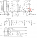
In the next time I will also redrawn those circuit diagrams, where the original schematic documents are difficult to read.

Most listed models I have found about
Threshold-Audio.com

First Series:
800A 200 Watt/Channel STASIS Stereo Power Amplifier (1975-77)
800S ???? unknown
400A 100 Watt/Channel STASIS Stereo Power Amplifier (1976-79)
4000 200 Watt/Channel STASIS Stereo Power Amplifier (1977-79, successor 400A)
800A Schematic
Threshold 800A and 800S
Threshold 800A Help!
http://www.diyaudio.com/forums/pass...els-mospec-2n5876-2n5878-mj21193-mj21194.html
Threshold 800A assistance
400A or Stasis 3?
Threshold 400 a
Threshold 400 A
Buying a 400A
http://www.diyaudio.com/forums/pass-labs/131030-would-work-400a.html
Threshold 400A HELP !!
Threshold 4000
Threshold! (4000 vs 800A)
Threshold (4000 400A CAS1)
Elettronica audio - (a cura di Piercarlo Boletti): QUAD 405 - 2 - Seconda parte (800A - high resolution schema, scroll down)
http://www.diyaudio.com/forums/pass-labs/55055-threshold-400a-parts-substitution-mods.html
Threshold 400A Power supply help
AudiogoN Reviews: Threshold 400a Amplifier (photo)

Cascode Amplifier (CAS) Series (Emitter Cascode Follower as Power Buffer)
CAS-1 75 Watt/Channel STASIS Stereo Power Amplifier (1979-81)
CAS-2 125 Watt/Channel STASIS Stereo Power Amplifier (1979-81)
THRESHOLD CAS-2 poweramp.
Threshold CAS 1
Threshold (4000 400A CAS1)

Stasis-Series:
STASIS-1 200 Watt STASIS MonoBlock Power Amplifier (1979-81)
STASIS-2 200 Watt/Channel STASIS Stereo Power Amplifier (1979-81)
STASIS-3 125 Watt/Channel STASIS Stereo Power Amplifier (1979-81)
SA-1 160 Watt STASIS MonoBlock Power Amplifier (1984-88)
SA-2 100 Watt STASIS MonoBlock Power Amplifier (1984-88)
SA-3 50 Watt/Channel STASIS Stereo Power Amplifier (1984-88)
S/150 (two series) 75 Watt/Channel STASIS Stereo Power Amplifier (1982-84)
S/200 (two series) 100 Watt/Channel STASIS Stereo Power Amplifier (1984-86)
S/300 (two series) 150 Watt/Channel STASIS Stereo Power Amplifier (1983-88)
S/500 (two series) 250 Watt/Channel STASIS Stereo Power Amplifier (1983-88)
S/1000 (two series) 500 Watt STASIS MonoBlock Power Amplifier (1984-88)
SA/3.9e 60 Watt/Channel STASIS Stereo Power Amplifier (1990-94)
SA/4e 100 Watt/Channel STASIS Stereo Power Amplifier (1989-95)
SA/6e 125 Watt STASIS MonoBlock Power Amplifier (1990-94)
SA/10e 175 Watt STASIS MonoBlock Power Amplifier (1990-94)
SA/12e 250 Watt STASIS MonoBlock Power Amplifier (1989-95)
stasis 2 and 3 schematics
http://www.diyaudio.com/forums/pass-labs/64795-stasis-2-problem.html
http://www.diyaudio.com/forums/pass-labs/92677-stasis-one-meter.html
Threshold Stasis 2.
Threshold Stasis 2.
threshold stasis 2
Threshold Stasis Model 3
http://www.diyaudio.com/forums/pass-labs/92618-another-threshold-stasis-2-rebuild.html
http://www.diyaudio.com/forums/pass-labs/34288-threshold-stasis-3-too.html
Stasis 3 Power Transistors
http://www.diyaudio.com/forums/pass-labs/112339-threshold-s-200-a.html
http://www.diyaudio.com/forums/pass-labs/158093-threshold-sa-sa-e-series-monoblocks.html
Stereophile: Threshold SA-1 monoblock power amplifier (SA-1)
Schematic and help with Threshold SA/4 (post #34: Instruction for bias adjust)

Threshold's New-Owner Series:
T 50 50 Watt/Channel Stereo Power Amplifier (1994-98)
T 100 60 Watt/Channel Stereo Power Amplifier (1994-98)
T 200 100 Watt/Channel Stereo Power Amplifier (1994-98)
T 400 150 Watt/Channel Stereo Power Amplifier (1994-98)
T 800 and T 800D 200 Watt/Channel Stereo Power Amplifier (1996-98)
TA-300 150 Watt/Channel Stereo Power Amplifier (1993)
S/160 80 Watt/Channel STASIS Stereo Power Amplifier (1992-94)
S/250 125 Watt/Channel STASIS Stereo Power Amplifier (1992-94)
S/350e 150 Watt/Channel STASIS Stereo Power Amplifier (1990-94)
S/450e 200 Watt/Channel STASIS Stereo Power Amplifier (1990-94)
S/550e 250 Watt/Channel STASIS Stereo Power Amplifier (1990-94)
S/1600 750 Watt STASIS MonoBlock Power Amplifier (1989-1994)
Threshold SA/2 SA/3 Soderburg site?
http://www.diyaudio.com/forums/pass-labs/144136-biasproblems-threshold-sa-1-a.html
http://www.diyaudio.com/forums/pass-labs/146232-schematics-threshold-series-i-ii.html
http://www.diyaudio.com/forums/pass-labs/142576-threshold-s-1000-series-ii.html
http://www.diyaudio.com/forums/pass-labs/140152-help-schematic-threshold-s-1000-series-ii.html
http://www.diyaudio.com/forums/pass-labs/136361-threshold-sa-50-a.html#post1953481
diyAudio

Unknown models:
500 ???
500/II ???
Threshold 500II
maybe SA-500 and Stasis 500 MK-II ??

not mentioned power amplifier models
about Threshold-Audio.com
but mentioned about http://www.audiopathways.com/Threshold.htm
preamp Stasis R 3.0 and 5.0
integrated Amp: Dragon V
5ch Power Amp: S-3500-E
Stereo Power Amp: Stasis 7.0 - Stasis 8.0 - S-5000-E
MonoBlock S-7000-E

Upgrade Kits:
???? ........................please let me know more, whether there are such kits or not.

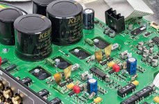
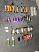
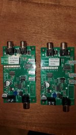
PCBs and special parts for various models:

various protection unit's: PCB part No 254-6000
Front end modules (FE-89, FE90), Universal FEB, Universal Error Correction PCB
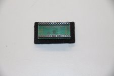
Universal LED Driver PCB for VU Light Band Displays (multi element bar graph array) e. g.
Electronics-Lab.com Blog VU meter
PCB for VU Light Band LED Display (multi element bar graph array)
VU Light Band VFD (Vakuum Fluoreszenz)-PCB
Analogue VU Moving Coil Panel Peak Indicator Meter
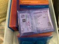
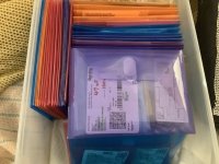
....................please let me know all the existing things - I have only found that from the attachement

Stereo Line + RIAA Preamplifier
NS-10 Stereo Preamplifier (1977-79)
http://www.diyaudio.com/forums/pass-labs/26003-threshold-ns-10-m1-info-wanted.html
http://www.diyaudio.com/forums/pass-labs/76557-threshold-ns10-lineamp-pcb-21.html?postid=1634684
SL-10 Stereo Preamplifier (1979-81)
Threshold sl-10?
threshold sl10
http://www.diyaudio.com/forums/pass-labs/151645-threshold-sl-10-a.html#post1937332
FET-1 (two series) Stereo Preamplifier (1981-85)
Threshold FET1
FET-2 (two series) Stereo Preamplifier (1981-85)
FET-9 Stereo Preamplifier with Phone Stage (1986-89)
FET-10Pc Stereo Phone Gain Stage (1986-89)
FET-10HL Stereo High Level Preamplifier (1986-89)
FET-9e Stereo Preamplifier with Phone Stage (1990-94)
FET-10Pe Stereo Phone Gain Stage (1990-98)
FET-10He Stereo High Level Preamplifier (1990-94)
http://www.diyaudio.com/forums/pass-labs/113706-threshold-fet-10-he-service-manual.html
Threshold Fet 10/hl Opinion ?
Threshold fet ten/pc schematics
T 2 Remote Control Stereo Preamplifier (1994-98)
T 3/T 3i Remote Control Stereo Preamplifier (1994-98)

crossover/DAC
PCX (-X10) Stereo Electronic Crossover (1987-89)
DAC1e Digital to Analog Convertor (1992-96)
DAC2 Digital to Analog Convertor (1995-98)

various URL's concerning Threshold devices:
Threshold Lovers - Threshold - Product line history
archiveamps
Stammtisch für HiFi- und Musik-Freunde | PASS LABS | Threshold
By Threshold history site not mentioned models: e.g. Stasis R-3.0 - Stasis R-5.0 - T Zero
Threshold Audo from AudioPathic

Attachments

Cambridge Audio 851N streamer mod

Hi guys,
Greetings from Lisbon, Portugal.

I have a Cambridge Audio 851N streamer with a Plinius Hautonga amplifier and Monitor Audio Platinum PL200II speakers.
Happy with the results and although the CA 851N sounds really nice for the price, it's probably the weakest link in my system right now.

I've been thinking about modding and tuning this streamer and would love to read your opinions.

1 - replace the standard voltage regulators (8 of them) by high quality discrete voltage regulators. These discrete voltage regulators can be found at around 10 USD/EUR each but the ones from Sparkos cost around 40 USD. This would be a 320 USD/EUR mod.
I actually found an article about this specific mod:
Cambridge Audio Azur Reviewed with Discrete Voltage Regulator Upgrade

2 - Swapping the 6 opamps for better ones.
Again, someone has done it.
https://hifi-ifas.de/cambridge-audio-851n-hoerwege-vs-cambridge-851n-streamer-test

3 - Replace the capacitors
4 - Replace the RCA plug for WBT plugs

Would love to hear your opinions one the benefits of these mods.
I know that high-quality components produce better results, just not sure if some mods are worth it when it comes to cost/benefit.

Thank you
Andre Antunes

diy 03 ways, hifi, close speakers

hi guys , im looking for , models brands constructions , hifi woofer , from 10'' TO 15'', low fs , for diy , close speakers , hifi quality sound
-max , rms power , could be 150 W ,- fs could be as low as possible , -4 to 8 ohms impedance , -qts for close charging case , may 0.6
thanks for any help suggestions , brands , good quality produce
sorry about my english not famous
adding this woofer to existing , cabasse O2ways , antigua 220 model , rebuilding the speakers , from 02 ways , to 03 ways
may be changing or adding the crossover surely

thanks

PAM8403 stacking channels option

Hi,

I purchased a small board with the PAM8403 chip. Each channel can do approx. 24 dB gain. I'm working on a simple project using a probe (coil) for interference pickup that I want to make audible (headphones).
I may need more gain than 24 dB and I don't need stereo output. I'm wondering if I can route the output of the first channel to the input of the second channel.

Both outputs seem to be isolated from the ground (measuring > 1MOhm). Is there a way to stack both amplifying sections to get a single channel with up to 48 dB gain?

Regards, Gerrit

pam8403.png

A small hobbyist's component sorting

I've looked for various component sorting ideas. I've seen a youtube video of a binder that's normally used for trading cards, with pockets, but I don't like the idea of getting them in and out. If storage is really unavailable, you could do it. I liked the idea of coin pocket holders but still wanted something larger.

So I found these on amazon (referral link, this one is not) and they work a treat for me at least. They're 5.5 x 7.5 polypropylene envelopes, have a velcro fastener, and are more than enough rigid/stiff to be able to file them. I'm sure there others on amazon or aliexpress.

They have clear ones as well, though I don't mind the colors, that gave me some grouping ability. I tend to leave the components in their original parts bags from Digikey, Newark, Mouser, etc.. But I do highlight the values with a big marker and also mark (and update) quantities on the bags label. Or insert a small piece of paper/index card.
They can expand a bit to hold larger capacitors up to a reasonable size. I was worried they might be flimsy and tear easily at the seams but they were not. Anyways, they work really well for me at home home where space is a consideration. Couldn't do the parts bin even if I wanted to.

Attachments

  • component sortingA.jpg
    component sortingA.jpg
    82.6 KB · Views: 170
  • component sortingB.jpg
    component sortingB.jpg
    72.7 KB · Views: 163
  • component sortingC.jpg
    component sortingC.jpg
    86.7 KB · Views: 168

1/8" SHAFT ELMA SWITCHES

These are for sale since I already have enough of them to use. $30 each. 6 Position, 2 pole. 1/8" shaft with a length of 1 1/4". Of course, you can easily cut the shaft to desired length.
FWIW, the switches are actually grey blue color. For some reason my camera doesn't see it that way.

Attachments

  • P7010001.JPG
    P7010001.JPG
    223.4 KB · Views: 81
  • P7010002.JPG
    P7010002.JPG
    254 KB · Views: 83
  • P7010003.JPG
    P7010003.JPG
    230.1 KB · Views: 82
  • P7010004.JPG
    P7010004.JPG
    303.4 KB · Views: 95

Juma's Easy-Peasy Capacitance Multiplier

I have built many amps and have been working on improving my power supply ripple with the usual CRC or CRCLC circuits. My best effort was actually an Abletec SMPS followed by a CRC where I got 1mV ripple under quisescent bias current. With linear toroidal transformers, I could never get below maybe 5mV and that was with a lot of effort. However, in class A, start pulling a couple of amps and that rises to 20mV sometimes 100mV depending on your trafo and CRC filter setup.

Novi amp sa 2SK2013/2SJ313 - Solid State - diyAudio.rs

Juma's cap multiplier:

585920d1481786375-jumas-easy-peasy-capacitance-multiplier-juma-cx-schematic.png


Here is nice schematic of the basic core cap Mx for a single rail use by Jwksana:
36990363054_f4dbe6e8e2_z.jpg


I recently built a small class A designed by Juma based on the Pass F5 but using the little 2SK2013/2SJ313 MOSFETs in parallel.

F5 with 2SK2013/2SJ313

The amp works well and sounds very nice. It draws about 1.5amps continuously and I am feeding it with my usual class A power supply: a 400VA 18VAC Antek with a 33mF/0.12R/33mF CRC. I was measuring 20mV ripple per rail and audible hum was coming through when no music was playing.

Juma's plans for the little F5 also included a simple capacitance multiplier circuit. It was so simple I had to try it. I have tried others in the past but they were always more complex and typically used BJT's and Darlingtons that I did not have on hand. This one however uses a single IRFP240/9240 per rail, a few resistors and easy to find caps, and a diode. It was so simple I could P2P on the legs of the MOSFET sticking up in the air:

574338d1476275384-very-simple-quasi-complimentary-mosfet-amplifier-f5-j131-k2013-cap-multiplier-closeup.jpg


I powered it up, now fed from my usual CRC that had 20mV ripple under load. There is a 2v voltage drop so you will lose some headroom. However, if you plan ahead, just get a slightly higher voltage secondary rating transformer. Then I hooked it up to the amp and adjusted bias current to usual 1.5amps and now measured the ripple...

Cap multiplier under test with F5 amp and 1.5amps flowing:

574333d1476267068-f5-2sk2013-2sj313-f5-j313-k2013-capacitance-multiplier-works.jpg


I was floored to see the Fluke AC volts drop to 0.000V AC (across +/- rails at 40v total). Sometimes flickered to 1mV then back to zero again (Fluke 101 has 1% accuracy of measured value + 3, the number added to the least significant digit, data valid over 40Hz to 500Hz range). I would love to have an o-scope to see what it really is doing - but there was a significant improvement in the sound quality. The hum was gone. I will try in my class AB amps next but thought folks might like to try this. It is dead simple and so easy. Anyhow, I think I will be making many more of these in the future and a little PCB would be handy. Just wanted folks to know about what a great circuit this is and to give it a thumbs up! Thanks to Juma for designing it.

If you have any experience with cap multipliers, please share. I have seen the ESP one and the one by Keantoken. This one with a single MOSFET is the easiest one I have seen though.

Edit Nov 13, 2016: stereo cap multiplier on one heatsink.

579772d1479032560-jumas-easy-peasy-capacitance-multiplier-juma-cap-mult-closeup-02.jpg


Here is a really nice one by Olafk:

582178d1480173535-jumas-easy-peasy-capacitance-multiplier-psu_juma_ii_02.jpg


Nice 4 cap Mx on 100mm square PCB by Prasi:
640121d1507959350-jumas-easy-peasy-capacitance-multiplier-juma-cm-png


Gerbers on post 245

Here is another nice one by Prasi for use with external bridge block:
640344d1508086056-jumas-easy-peasy-capacitance-multiplier-juma-cm-external-diode-bridge-png


Small SMT/TO-220 Cap Mx (Dual rail) by Prasi:

714135d1541569887-jumas-easy-peasy-capacitance-multiplier-smd-lay-r1-png


720209d1544046993-jumas-easy-peasy-capacitance-multiplier-smt-cap-mx-build-03-jpg


Works very well.
  • Like
Reactions: Haze Head

Box size with high pass?

I am designing myself a center channel and had a question on box volume. This will be used with the high pass from my reciever set at 80htz. Does it matter what size I choose if all the F3's for the recommend box sizes are below 80htz anyway? Any negatives of building it to the biggest size/ lowest F3? I do prefer the larger size visually. The woofers will be 2 Silver Flutes 8" 4 ohm crossed over at about 250htz or so.

Full bridge rectifier with AC provided by one signal generator

Hi all
A member of my family is doing an experiment about full bridge rectifiers, and I think they are running into some trouble.

They have a signal generator making I believe 10v ptp AC being fed into the AC inputs of the full bridge rectifier (the negative half of the AC wave apparently being connected to signal generator ground), and the DC output being observed on an onscilliscope.

They were running into trouble where the negative half wave was not showing (googling and thinking about this, it's almost certainly due to shared grounds shorting the diodes that would deal with the negative part of the AC wave).

They can now see the "effect" of rectification using some built-in math operation on the scope.

This all seems weirdly wrong to me.

Surely:
1. There is no true AC current as the "bottom" diodes dealing with the negative wa e are only affixed to 0v ground
2. You can't have this circuit working without a transformer (or without 180 degree out of phase dual ac?)


A capacitor was placed (I presume in parallel to output of the bridge) and this appears to have skewed the 2 AC voltage traces on the scope in a strange "camel hump" way. Just seems the circuit I messed up, but I have no circuit diagram (and may not be able to get one).

Any thoughts please?

My only 2 times i have managed to get a full bridge working was via mains 240v AC and transformer (one of which I use daily in my lm3886 DIY build), so I'm a bit unsure if a bridge rectifier can be used without a transformer.

Shorting or non-shorting rotary switch

I am looking for a 2 pole, 12 position switch. I will be using it to switch between two 6 channel devices an AVR and a multichannel dac. So it will be between the dac or AVR and the Amps. Amps will be solid state. Working on a 5 channel Modulus 86 amp. The rotary switches come in two varieties either shorting or non-shorting. Shorting would be a “make before you break” scenario and the non-shorting would be a “break before you make” scenario. So which would be best for my situation? Not planning to switch the ground wires, just the signal wires.

Mark Johnson / Gtose Cap Multiplier

This is a capacitance multiplier designed by Mark Johnson and Gtose. It was first discussed on the Juma’s Easy Peasy Capacitance Multiplier thread. I have created a dedicated thread for it here to reduce confusion as folks have been posting questions about it on the other thread.

A big thanks to @Mark Johnson , @gtose , and @prasi for making this available to the DIY community.

The layout was done by Prasi and details and Gerbers here:
https://www.diyaudio.com/forums/pow...peasy-capacitance-multiplier-post5510507.html

The BOM is here:
https://www.diyaudio.com/forums/pow...peasy-capacitance-multiplier-post6161883.html

Schematic:
cap-mx-gtose-mjohnson_sch_r1-png.1086778


Layout:
IMG_5534.jpeg


Assembled PCBA example of later variant with active bridge by @passive420:
IMG_5535.jpeg


If @prasi can please insert all of his associated designs in this thread that would be great.

Please continue technical discussions here.
  • Like
Reactions: Uunderhill

For Sale USG Muse Preamplifier PCBs and Parts

Hello all,

I have a complete set of new PCBs for this UGS pre. I started to assemble the two shunt regulator boards, but due to some inaccurate silk screen labeling, I blew a couple of the SMDs on one board and was never able to get it to work. I have all the parts still unassembled for the boards, except for the one shunt regulator PCB. That will require some rework. I decided not to continue with the project, and it's been boxed up on the shelf ever since.

I have roughly ~$1000USD invested in this project, that will never likely get finish, so that's why it's for sale. I'm asking $750, plus Priority Mail shipping to the USA only, or reasonable offer.

Please PM me if your interested and I will provide pictures and detail.

Rick
  • Like
Reactions: angchuck

Are there any equivalents for the 2SJ56 and 2SK176, even in a different case?

I have a pile of amplifiers that use the 2SJ56 and 2SK176 TO3 outputs. I personally don’t know if there is anything wrong with any of them, but after opening one of the amps it seems that those are the only parts that might be tricky to replace. Is there a mosfet in to TO3P package and any other package that might work if I’m needed to replace some? I really hope I don’t have a huge stack of paper weights. They are Hafler Pro5000 amplifiers for those that want to know.

Dan

CJ MV55 questions and help.!

Hi there,

I have a MV-55 that I would love some help with; first thing is how can I lower the plate voltage so I can safely run Tung Sol 7581A’s ideally I would like to install a switch that would toggle between the two voltages, any suggestions on how to do this would be greatly appreciated…. Secondly would there be any other modifications required for the bias circuit if the above is doable?

GNFB, I’m struggling to find any information about the circuit and topology, can anyone tell me what level of NFB (if any) the amp has? I’ve obtained a schematic however it seems hand drawn and barely readable..!!

Output seems to be set at 4ohm, there are 2 conductors each (hot and cold) form the opt to binding post and one additional ground wire from the star point on the PCB to the cold BP terminal, also one conductor from the hot BP terminal to the PCB close to the front most bias pots..?? I would like to switch between 4 & 8 ohm if that’s possible with a modification?

Any help in understanding how this amplifier works would be appreciated.

Cheers.!

For Sale Rubycon Black Gate N Capacitor Non-Polar 100uF / 16V High Quality Electrolytic

New NOS Rubycon Black Gate N bipolar electrolytic capacitors 100uF / 16V high quality bipolar (non-polar) for signal coupling use. Sold as a pair of two (2). No other Black Gate values are available. No trades or offers please. USA shipping only. $90 plus First Class mail cost; postal insurance is optional. Please pm.

Attachments

  • IMG_4529.JPG
    IMG_4529.JPG
    164.5 KB · Views: 187

A slightly unusual Rogowski sensor

Hi there,

This Rogowski sensor is perfectly ordinary, except for one detail: the sensor coil is wound on the inner conductor of a RG316 coaxial cable.

This type of SHF cable has its inner conductor made of steel, because mechanical resistance is more important than ohmic resistance.

This means that the coil is no longer air-cored, as for a regular Rogowski: the core presents some magnetic permeability. In this case, it is low, because steel has poor magnetic properties, and occupies only a fraction of the core area: the equivalent apparent relative permeability here is ~3.

Why would anyone compromise the main virtue of Rogowski coil, linearity, by adding an imperfect, non-linear core?

Rogowski's are great, but they have a very low output, which is furthermore affected by a 6dB/octave slope, meaning their low-frequency output becomes quickly drowned in noise after the integrating conditioner.

Increasing the permeability improves matters, here by ~10dB: this doesn't look much, but it is far from negligible.
Of course, it also degrades the linearity, and adds a supplementary frequency-dependence: beyond ~20KHz, the steel begins to lose its properties, because of the eddy-currents and the skin effect in the silver plating. This requires additional equalization, but it's no big deal, and for a wide frequency range, equalization is required anyway.
The linearity aspect would become a problem at very high currents only: because the apparent permeability is so low, other effects are "diluted".
I estimated that non-linearities would become an issue for currents of the order of ~1kA.
This could be a problem for me, as I intend to reach peak currents of 1.5kA, but because it will be for a few µs only, it should not be a problem: the magnetic field will not have enough time to penetrate the steel core, and the coil will behave mostly like an air-core one

Attachments

  • Rogo0.png
    Rogo0.png
    68.5 KB · Views: 546
  • Rogo1.jpg
    Rogo1.jpg
    458.5 KB · Views: 513
  • Rogo2.jpg
    Rogo2.jpg
    248.6 KB · Views: 459
  • Rogo3.jpg
    Rogo3.jpg
    521.4 KB · Views: 460
  • Rogo4.jpg
    Rogo4.jpg
    507 KB · Views: 421
  • Rogo5.jpg
    Rogo5.jpg
    525.2 KB · Views: 311
  • Rogo6.jpg
    Rogo6.jpg
    216.5 KB · Views: 370
  • Like
Reactions: Bigun

Conrad Johnson MV50 adjustment?

Just bought a 2nd hand CJ MV50 power amp. I'm surprised by the bias setting of the EL34 output tubes. Because of the 220V to 230V switch during the last 10 years or so, the tube has more than 500V on the plate while the optimal idle current has around 60mA on the meter. That means using the tubes on the edge and implying a short tube life (1000-1500 hours I guess).

So I'm not feeling relaxed about that. The bias can be adjusted by individual trimmers using the famous red led of CJ. Of course I can neglect the LED and just turn to a current of around 45 mA. The problem then is that the negative voltage supply (that gives the bias) end at around -47V which is not enough for all tubes to do the setting. So I have to mod the bias circuit.

Then the problem is: I can't use the visual inspection of the LED's anymore. To re-use that I have to mod the bias circuit yet once more.

Still another option is to bring down the input voltage of the high tension. I can put 47ohm/5Watt resistors in each AC line to lower the DC to around 470V or so (just guessing, total current for all tubes will be around 250 mA). These will become hot, being just a waste of power. But, heh, you have to bring in an offer to save some tube life.

Then again: I don't know how this all will change the sound of the (now very good sounding) MV50.

The last option maybe is using a more robust tube like the 6550 of some KTxx. This I don't like because of the nice character of the EL34 (not forgetting its lower price and fine availability) and then once again I have to change the bias circuit too.

So: I'm not sure what to do. What would you do? Any advice is welcome. Maybe some MV50/52/55 owners out there.

speaker protection relay - do I need diodes across the coil?

as above. I bought a ready-made PCB with all the parts installed and noticed there's no diode across the relay. should I put one? if yes, would a normal 4007 work?

Thank you.
EDIT: there are 2 relays (1 each for both channels)and using a meter, it seems 2 ends of the relay coil are connected to each other. (not sure if this matters but I thought it might be important)

New FDNR topology? Spot the flaw in its behaviour

I was trying out various gyrator topologies, emulated and for real and stumbled across one I don't think I've seen before:
FDNR_variant.png

It looks like a NIC stacked on top of a NIC, but note the opamp input polarities are inverted from the normal. (The choice of opamp for emulation is arbitrary by the way, I used a NE5532 for the physical realization)

This sort of makes sense as this guarantees high frequency feedback is negative and thus stability. It does emulate and work for real. Changing the capacitors for resistors will destabilize this topology so its only suitable for a FDNR, not a grounded inductor.

But there's another catch.

Although its basically stable it can misbehave, and does so in real life - thought I'd leave this for people to muse over and figure it out.

[I should add that this is not intended to be voltage driven, the real life circuit has a source with an impedance of several kohms]
  • Like
Reactions: Elvee

Are my 2SJ56 and 2SK176 mosfets healthy?

I posted a thread a bit ago, asking about replacements for these outputs. I was given a stack of amplifiers that use these outputs. They stopped working, and the person to own them took them to a repair shop and the repair shop refuse to work on them since they couldn’t get parts for them. So he gave them to me. I thought for sure that it would have all shorted outputs, then I would at least have big transformers, and heatsinks if I parted them out. Well, I pulled all 12 mosfets from the first amp and not one was shorted, but they did measure differently on my Peak Atlas DCA75. Some measured as Enchantment mosfets and some as depletion mosfets, yet the specs the meter was giving me was very similar. There was no rhyme or reason as to where the depletion mosfets were. Here is an example, I pulled the 3 2SJ56 from one’s channel and here is how they measured.

IMG_7009.jpeg


The two with the E above them measure at Enchantment and the one with the D above it, well you know. You can see that the measurements the meter gave me are all right in line with the others. Is that just an artifact of the mosfet interacting with the meter? Are they perfectly fine to use?

Thank you,
Dan

For Sale NOS 6P14P-ER Vacuum Tubes

Hi,

I have for sale NOS 6P14P-ER Vacuum Tubes.

Highest grade of 6P14P "ER" version, long life / high reliability.
Reflector Saratov factory, made in 198x.
Some tubes have silver getter, some black-silver, which is completely normal.
Close-up photo of the tubes enclosed so you can see that they are 100% new and not used.

14.95 Euro / pc
Shipping flat rate from EU zone to EU zone only, by post with tracking number. For example, 5 pcs - 10 Euro, 10 pcs - 15 Euro.
Due to the age of item(s) sold as is, no warranty or return.

Photo 23-06-27 14-05-52 7599.jpg
Photo 23-06-27 14-07-10 7600.jpg

Any very good sounding tube headphone amp ideas?

Dear all, I'd like to build my very first tube headphone amp.
Any ideas, a simple schematics maybe ? I'm not an electrician but I can solder and had some little projects already, all with success.

My headphone's parameters:
Max. power rating: 0.05W (50mW)
Max. voltage: 1.2Vrms (3.3Vpp)
Max. current: 43mA
Max. S.P.L.: 113dB
Impedance: 28 Ω
Efficiency: 96 dB/1mW (111dB/1V)

In the future I'd like to be able to drive some more serious headphones with it too, like Sennheiser's HD800S, which seems to be a very different animal (300 Ohms if I'm correct).

I prefer JJ tubes, we have easy access to them in Europe, but actually any brand might be okay as well.

Many many thanks :wave:

2 X 18 B&C 18SW115 Cabinet

Hi dear members. Someone can please help me finding or designing a cabinet for 2 B&C 18SW115? loud outdoor techno, edm, trance and psy trance is the main goal, but i have a problem.. A really big problem. max large 100cm (39,37 inches) not a single cm more or it wil not enter the trunk of my car. I like a lot the style of the EV MTL1 but is too large.. please help me

For Sale CS8412 To CS8414 Upgrade Module

New Crystal CS8412 to CS8414 digital receiver upgrade module for 96kHz/24bit operation. Local power supply bypass capacitors.
This adapter replaces CS8412 digital input receiver with the newer 96kHz compatible CS8414. $60 each shipped. PayPal only. 2 are available.

Sold "as-is" and no warranty is expressed or implied. No returns or refunds. Sells and ships to USA residents only.

Attachments

  • IMG_4659.JPG
    IMG_4659.JPG
    265.9 KB · Views: 88
  • IMG_4663.JPG
    IMG_4663.JPG
    230.5 KB · Views: 99

connecting SME 3009 S2 (ground)

Hi friends
I am redoing my father's TD-125 with SME 3009 S2 imp, and renew the wiring to the pre-amp.
when I opened the connector, I saw that he connected the arm's ground to one channel's ground, thus avoiding a separate gnd-wire...
That sent me into research-modus, and now I am confused.
On one side, I think it is better to go after the books and have the tonearm-/chassis-gnd separated from signal-gnd, on the other hand someone was saying something like "the ground-wires' capacitance adds up... here: https://www.diyaudio.com/community/...ld-style-cable-connector.278825/#post-4438868

What do I do with that? (I'm actually tempted to believe the shield's capacitance does not interfere with the signal's)
So it is still better to keep gnd separated, yes?

Thank you so much!

Attachments

  • 30469336-B9B4-4FDD-B368-7D3B864C1695_1_201_a.jpeg
    30469336-B9B4-4FDD-B368-7D3B864C1695_1_201_a.jpeg
    435.8 KB · Views: 177
  • F1B28EB1-5532-435C-AAA2-CD22418872A2_1_201_a.jpeg
    F1B28EB1-5532-435C-AAA2-CD22418872A2_1_201_a.jpeg
    376 KB · Views: 137
  • 8D19F140-6DC5-46BB-8AB2-31E0F959F859_1_201_a.jpeg
    8D19F140-6DC5-46BB-8AB2-31E0F959F859_1_201_a.jpeg
    531.4 KB · Views: 224

expert advice on reducing port chuffing on store bought powered subwoofer?

So I was given this little jamo sub210 8" ported sub that I want to sell locally to make a few bucks. It functions fine except it has a LOT of port noise. I temporarily stuffed the port just to verify all the noise I was hearing was from the port, and it was. Driver and amp seem totally fine. Port noise is so bad, you basically have to turn it down to the point of barely being audible/useful, so it's not a matter of me playing it too loud (volume was at 12 o'clock/half). I'm also aware of the factors that cause chuffing (too fast air speed due to port size or overdriving). The port is about 2" wide, about 4" long, and has flared ends. I'm not terribly concerned with slightly altering the tuning. I think a buyer would notice the loud chuffing before they'd notice a slight loss of output or tuning change. My options are (A) just plug the port. (B) Completely stuff the sub with polyfill ($5/bag) and leaving port open. (C) Completely stuff with polyfill and plug port. (D) Remove port, make the hole bigger by about and inch or two and install a larger port depending on how much room I have on the baffle. If I increase the port width, how do I determine the larger port's length? Btw, while the port was temporarily stuffed, I was playing bass sweeps and after a while I noticed one spot on the plate amp was very warm. Any chance of damaging the amp in case it relies on the air movement from the port for cooling? With the port open and playing bass sweeps, the air coming out of the port could be felt a couple feet away. Again, this was a normal listening levels (volume was at about 1/2 (half). Thx.

Denon PMA 1510ae Gain 45.5dB

Hi.

I'm looking to lower the gain of my Denon integrated. As it has to much gain for modern sources (input sensitivity is 125mV) and Gain in Amp stage is a whopping 45,5dB.

The easy way would be to add some external attuniator s i guess, but that feels like a bad solution.

I would like to reduce the stepup in the voltage amp stage but sadly my skills in electronics are not up to par with the task.

So is there any experts here that can advise on any adjustments so that the input sensitivity would be about 300-500mV,and gain 39-34dB

Attachments

Matching BG RD75 planars with Magneplanar ribbon tweeters

Hi all,
I have a pair of BG RD75 planars.
They are crossed over with some Marchand XM46 line level passive crossovers driven by Conrad Johnson Premier 8XS' monoblocks. I have been using 3 pairs of Aurum Cantus G2Si ribbon tweeters but plan on replacing these with some 60 inch Magneplanar ribbon tweeters for a true matching line source. I imagine that these are a natural pairing. I was hoping that someone might have some suggestions re; crossover frequencies/slopes and designs.
Thanks in advance.
Cheers, Peter

Will this tweeter work well in one of these circuits?

My friend owns a the pair of speakers featured on Paul Carmody’s website, the older, original Carrera using the 15w Revelator and Hiquphon OWIII (has the gold dome). It uses the original OWIII that was replaced with the OW3 when they needed to change the dope used on the dome.
IMG_6723.jpeg


It uses this crossover.
IMG_6841.png

IMG_6842.png


Since the OWIII went away Paul swapped over to the OW1 using this crossover.

IMG_6839.png

IMG_6840.png


Of course the woofer circuit had no changes. My friend said this is hands down one of his most favorite pair, he listens to them daily. I have a large collection of raw drivers and I’m wanting to build something with what I have on hand and of course I have interest in building this-ish.

I have the correct woofer, but the tweeter I have is the OW2, falls right between the two lol. After doing some reading I found out that the OW2 has less mass and is considered a faster tweeter, better with the upper end while not being as clean with lower frequencies. My friend and I talked a we agreed that of the two crossover that the one designed for the OWIII would be the one to start with. Being that the OWIII and OW2 have the same 90db sensitivity while the OW1 is 87db. Also the frequency response for the OW2 ans 3 look nearly identical.

Here are the specs, I’m basically just wanting to know if this idea is worth the effort of moving forward and of the two crossovers which would you use.
IMG_6960.jpeg


I would love to get started on this build, but only if it makes sense and will sound good. I wish I had one of the drivers that Paul designed with, but spending any extra money right now isn’t going to happen.

Dan
Projects by fanatics, for fanatics
Get answers and advice for everyone wanting to learn the art of audio.
Join the Community
507,774
Members
7,887,995
Messages

Filter

Forum Statistics

Threads
406,213
Messages
7,887,995
Members
507,774
Latest member
pete2000