My friend owns a the pair of speakers featured on Paul Carmody’s website, the older, original Carrera using the 15w Revelator and Hiquphon OWIII (has the gold dome). It uses the original OWIII that was replaced with the OW3 when they needed to change the dope used on the dome.

It uses this crossover.


Since the OWIII went away Paul swapped over to the OW1 using this crossover.


Of course the woofer circuit had no changes. My friend said this is hands down one of his most favorite pair, he listens to them daily. I have a large collection of raw drivers and I’m wanting to build something with what I have on hand and of course I have interest in building this-ish.
I have the correct woofer, but the tweeter I have is the OW2, falls right between the two lol. After doing some reading I found out that the OW2 has less mass and is considered a faster tweeter, better with the upper end while not being as clean with lower frequencies. My friend and I talked a we agreed that of the two crossover that the one designed for the OWIII would be the one to start with. Being that the OWIII and OW2 have the same 90db sensitivity while the OW1 is 87db. Also the frequency response for the OW2 ans 3 look nearly identical.
Here are the specs, I’m basically just wanting to know if this idea is worth the effort of moving forward and of the two crossovers which would you use.

I would love to get started on this build, but only if it makes sense and will sound good. I wish I had one of the drivers that Paul designed with, but spending any extra money right now isn’t going to happen.
Dan
It uses this crossover.
Since the OWIII went away Paul swapped over to the OW1 using this crossover.
Of course the woofer circuit had no changes. My friend said this is hands down one of his most favorite pair, he listens to them daily. I have a large collection of raw drivers and I’m wanting to build something with what I have on hand and of course I have interest in building this-ish.
I have the correct woofer, but the tweeter I have is the OW2, falls right between the two lol. After doing some reading I found out that the OW2 has less mass and is considered a faster tweeter, better with the upper end while not being as clean with lower frequencies. My friend and I talked a we agreed that of the two crossover that the one designed for the OWIII would be the one to start with. Being that the OWIII and OW2 have the same 90db sensitivity while the OW1 is 87db. Also the frequency response for the OW2 ans 3 look nearly identical.
Here are the specs, I’m basically just wanting to know if this idea is worth the effort of moving forward and of the two crossovers which would you use.
I would love to get started on this build, but only if it makes sense and will sound good. I wish I had one of the drivers that Paul designed with, but spending any extra money right now isn’t going to happen.
Dan
It can (be made to) work, especially if you have measuring gear. The OW2 and OW3 have higher sensitivity hence the greater padding. Impedance changes between each one would affect the parts values in the filter to get the desired slope. I would think the original XO would be a good starting point, but there's no guarantee it will be as per the original design unless the frequency response and impedance plot is identical to the original tweeter used for it.
I believe Hiquphon give you the measurements with each pair, yes? Or maybe Dave Ellis has them. If you can get them for the different versions of the OW3/OW2, you can use simulation software to replicate the original transfer function with the published schematic.
I believe Hiquphon give you the measurements with each pair, yes? Or maybe Dave Ellis has them. If you can get them for the different versions of the OW3/OW2, you can use simulation software to replicate the original transfer function with the published schematic.
Last edited:
(not knowing the drivers sonically) It appears to my eyes that the second circuit is sonically superior.
Although both circuits are what I call 'quasi third order', the second circuit is closer to second order.
In my experience, I have always found second order filters to be more 'musical' than third order.
The second circuit would likely also exhibit a 'sweeter' extreme top.
Although both circuits are what I call 'quasi third order', the second circuit is closer to second order.
In my experience, I have always found second order filters to be more 'musical' than third order.
The second circuit would likely also exhibit a 'sweeter' extreme top.
3rd order on the tweeter.
Actually pretty smart, better way too do it.
Keeps things cleaner at higher power levels.
And likewise it is close to 3/4" dome so it should hold up
pretty good on the top end.
pretty nice tweeter.
Otherwise looking at data sheet, it is not hiding upper cone
break up. Its actually rather smooth top end on the woofer
as well.
Small baffle, so baffle step make highend look peaky
flattened out with a notch.
Mainly baffle compensation.
every designer approaches things different.
1 or 2 different ways to compensate
a small baffle
Long as it sums and impedance curve doesnt get
too silly.
Nice to see smaller tweeters on steep filters.
good off axis, handles power.
Cross reference to your post on the PETT just in case Paul C replies to that one.
https://techtalk.parts-express.com/...making-a-slight-tweeter-change-to-the-carrera
https://techtalk.parts-express.com/...making-a-slight-tweeter-change-to-the-carrera
Dan, use Craig's filter to start with. If you feel the transition is a little weak between the drivers, step the 2.2uF to a 3.3uF. I would not touch the padding resistors. Absolutely use the LCR across the woofer to kill the ring the 15W are known for.
Sim with OWII tweeter and using posted Carr crossover. Less padding than other design with 12 ohm pad
room response. 8 ft ceiling On stand 29 inch from floor.
Its ok horizontal should be better, power response with whoopy doo impedance , needs tuning
3/4 tweeter with 5 inch ish woofer. great concept good recipe for nice system.
checked out tweeter manufactures site. impressive
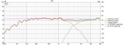
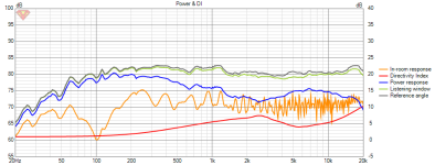
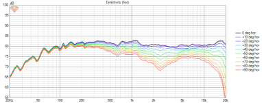
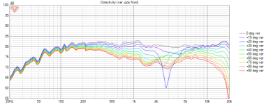
room response. 8 ft ceiling On stand 29 inch from floor.
Its ok horizontal should be better, power response with whoopy doo impedance , needs tuning
3/4 tweeter with 5 inch ish woofer. great concept good recipe for nice system.
checked out tweeter manufactures site. impressive


The thing i find interesting is many Scanspeak drivers have that typical wiggle in FR from cone to surround reflections. I wonder why they decide not to do anything about that being such a hugh end driver. I understand you don't want to over dampen the suspension to minimize losses in the upper FR, but the cone breakup modes can be very pronounced on these drivers, which makes xovee design very challenging.
Just few minor changes to component values and
seems to be alright. Slight changes to some coils and caps.
Smoothed out impedance curve a lot. And Horizontal
improved. Vertical is what it is. Only way to change is center
to center spacing and that is physically impossible.
Before

After
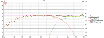
played with room position, its sim.. so is what it is.
But actual power response seems better.
Dip goes away in room, against rear wall, with generic
1 meter from side wall and 20 degree toe in.
On a stand, 8ft ceiling same.
Before
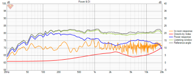

After
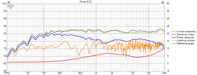

value changes made based on sim
mainly just padding and slight values to improve
horizontal and smooth out notch.
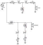
Impedance curve flattened
and closer to 8 ohms
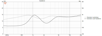
original
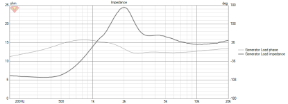
matches

seems to be alright. Slight changes to some coils and caps.
Smoothed out impedance curve a lot. And Horizontal
improved. Vertical is what it is. Only way to change is center
to center spacing and that is physically impossible.
Before
After

played with room position, its sim.. so is what it is.
But actual power response seems better.
Dip goes away in room, against rear wall, with generic
1 meter from side wall and 20 degree toe in.
On a stand, 8ft ceiling same.
Before

After


value changes made based on sim
mainly just padding and slight values to improve
horizontal and smooth out notch.

Impedance curve flattened
and closer to 8 ohms

original

matches
Cross reference to your post on the PETT just in case Paul C replies to that one.
https://techtalk.parts-express.com/...making-a-slight-tweeter-change-to-the-carrera
Holy smokes, this thread has blown up. Yeah I posted the same question over at PE, but I was getting no answers at all. I also posted a thread as it’s become miserable to post there. I just checked it and Paul has commented, so I’ll have to go back and read that thread too, thank you.
Dan, use Craig's filter to start with. If you feel the transition is a little weak between the drivers, step the 2.2uF to a 3.3uF. I would not touch the padding resistors. Absolutely use the LCR across the woofer to kill the ring the 15W are known for.
Thank you for commenting Ben, exactly the advice I was looking for.
Just few minor changes to component values and
seems to be alright. Slight changes to some coils and caps.
Smoothed out impedance curve a lot. And Horizontal
improved. Vertical is what it is. Only way to change is center
to center spacing and that is physically impossible.
Before
View attachment 1187037
After
View attachment 1187036
played with room position, its sim.. so is what it is.
But actual power response seems better.
Dip goes away in room, against rear wall, with generic
1 meter from side wall and 20 degree toe in.
On a stand, 8ft ceiling same.
Before
View attachment 1187039
View attachment 1187043
After
View attachment 1187040
View attachment 1187042
value changes made based on sim
mainly just padding and slight values to improve
horizontal and smooth out notch.
View attachment 1187046
Impedance curve flattened
and closer to 8 ohms
View attachment 1187047
original
View attachment 1187049
matches
View attachment 1187050
Wow! Thank you so much. That looks like a very nice response. I’ll mock up both crossovers and take a listen. I really appreciate your time into this. If people care to know, I’ll post my thoughts here, though it will be purely subjective.
Very refined and impressive design going on here 🙂
I agree!
Dan
That LCR did the trick. Very nice sim results. I wonder how much baffle diffraction influences that. I would think the amount of BSC would reduce efficiency more, but that FR looks great.
I am leery of the sim recently posted above only because the Hiq is a 22mm tweeter, and it runs the tweeter a little lower than the Untitled or Carrera derivatives. Taking an HD sweep of the OW2 in situ will further inform whether it's happy in that arrangement.
- Home
- Loudspeakers
- Multi-Way
- Will this tweeter work well in one of these circuits?