I owe NickS (Ugly Woofer) for the light bulb on the name. He said they 'resemble putting a ship in a bottle'. Mix with Battleship, and voila!
So, if you thought the
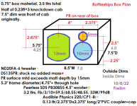
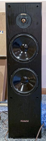
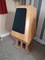
Purveyor were small, these are shoehorned into HALF that volume. You likely now think I've sincerely lost my mind. These are the smallest 3ways I've both seen and heard (of) in DIY circles. The Purveyor were 5.25"/2.5"/1.0" arrangement, and the new 'ships are 4"/2"/0.75". There is no way a 5.25" woofer would fit and perform well in a total of 3.5 ltrs, nor will the drivers fit on the baffle without using a 4" or smaller woofer. If I want the bass extension, a 3" with good bass performance would be too low in sensitivity for my requirements, so a 4" it has to be. Next problem is that the number of 4" with great bass performance is even fewer than that of the 5.25" pool of options. I settled on the Peerless SDS 830855, $19 at PE, and a supposed 86dB sensitivity. The obvious next choice is that of a 5.25" PR to align the stars for the best maiden voyage into bass dredging. (Looking around, I feel that the Dayton TCP115-4 could be a viable woofer substitution with some xover rework, as long as it fits on the baffle.)
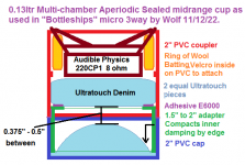
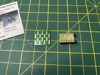
So, putting this info above into practical use, the mid I decided on is the Audible Physics 220CP1 8ohm from Newark/Farnell for $22. It's a carbon paper cone with an aluminum dustcap, cast frame, 86dB sensitivity, and a large Neo motor. Being that Chuck (isaeagle1031) and others have really liked the AP stuff, so I didn't even second guess my choice at the cheap price per. I had to try it after seeing it in Brandon's thread a little while ago. I fiddled around with 4-5 different chamber arrangements empirically modeling and physically testing them until I came upon another of my 'ice-cream sandwich' type alignments, or Multichambered Aperiodic sealed; AKA MAPD from Northcreek fame. Being a 2", and being primarily used from 700Hz+ as an estimate, the amount of volume required is small. However, the Fs magnitude and frequency is fairly high and could stand to be minimized a bit to aid in xover simplicity and damping of the rolloff. Using a 2" PVC coupler and endcap, a 1.5"-2" adapter, 2 equal pieces of Bonded Logic or Ultra Touch, a ring of wool batting, and a bit of E6000 adhesive; sufficed for a 0.13 ltr chamber.
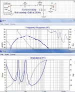
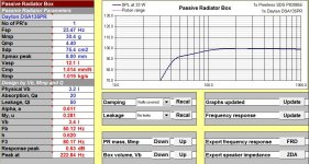
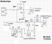
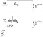
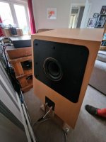
Further on the boxes... Being of minimal midrange volume, this lent the woofer volume to be ~3.2 ltrs. Using the DSA135 PR without added mass models to Fb/3/10 of 60/68/48Hz, or a very gradual rolloff. Trying to conserve sensitivity, using a steel-laminate coil creates a bump in response around the Fs of the woofer of a dB or two. Then using a 730uF Passive Assist capacitor in combination with the highish Fs and the higher Q of a vented box, while gaining another order on the rolloff, actually also extends the lowend a smidge here. (I have a HUGE box of 330uF polarized caps, and I have been making large NPE caps with them for awhile now.)
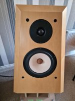
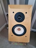
I am using the Dayton ND20FA-6 because I have them, and it fits atop the mid on the baffle. They are tiny, but look big on these small speakers. The main positioning of the drivers on the baffle actually involves the midrange chamber as the most influential information. Acoustic offsets are at 2" from midrange to tweeter, and 4" from midrange to woofer. Unfortunately, this also means that the truncated Peerless MUST be mounted vertically to get everything to fit.
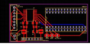
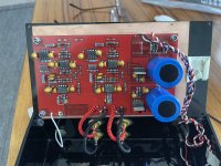
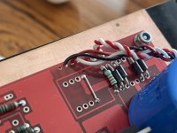
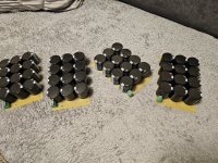
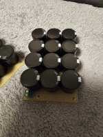
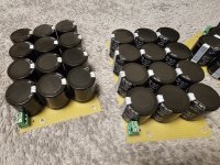
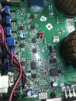
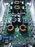
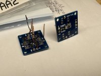
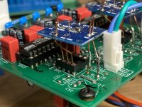
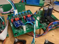
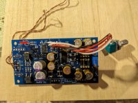
The xover as modeled and refined represents 17 individual components. I can hear the gasping and see the whites of your eyes now.... In this portion I am using the smaller and cheaper parts I've acquired over the years, like 22AWG coils for the tweeter and midrange shunts, small mylar caps, and as few resistors as possible. "How you gonna fit all that $#!+ in that tiny box, dude!?" was the usual reply in conversation with the closest of you.
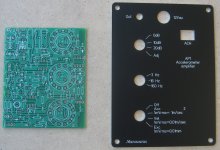
Well- it ended up requiring a 3D xover pegboard assembly. I've thought of doing this before, and have done daughter boards before a few times but never to this nth degree. It almost operates as a brace that press-fits vertically inside.
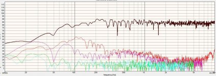
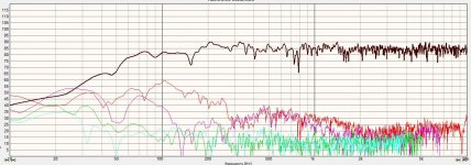
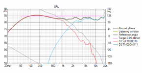
Now, a lot of you are likely thinking, "Why!? would you have a 3way with a 4" woofer?" The initial goal was to use the AP mid or any 2" mid effectively. Going further, the tweeter is good to 4kHz before HD rises. The AP has HD above 1% below the 750-800Hz region. The 830855 has dominant 3rd order HD above about 1.2kHz, even though it does not rise above 1% in amplitude. According to these frames of reference, it makes sense why the HD would be lower or better for these particular drivers utilized together.
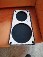
The mid takes #4 flush-head screws as the mounting holes are beveled. I bought some torx head "for plastic" screws that worked really nicely. The woofer/PR have #8 torx sheet metal screws. The tweeter is press fit and sealed with E6000 on the back. Woofer inside edge is beveled. To speed up the process, I used a self-selected hole saw set that I accumulated last year for Christmas. The largest is a 4.125" diameter for common tweeter faces. Cutting the perimeter of the rebates is the hardest part, then the remaining area can be removed swiftly with the trim router. It takes less time in setup and making the cuts than a full router solution for me. However, a router rabbet bearing set is also a valid counterpart to the hole saws.
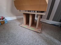
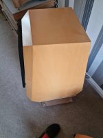
The finish is 2-3 coats of Watco Danish Oil, then Minwax Golden Oak stain. Being the grain is a bit open, I did something different this time. I used Permatex black silicone to cover the surface, and then slowly wiped off the excess. After that dried, I steel wooled the surface to remove the crumbs and excessive bits. Then a coat of polyurethane finished the front and back off. The chatoyance is pretty nice, and I really like the edge look. The main box section is built with pre-formica'd 3/4" particle board. I used full mitered corners for the finished assembly, and coated with epoxy for strength and durability.
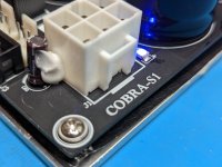
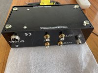
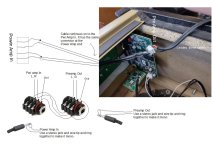
The inputs are rear mounted binding posts that did not have the front nut to clamp down. I grabbed a bag a couple years ago at a DIY event. Basically, I drilled a 19/64" hole, recess the entrance from the rear so it's closer to the front, and lightly beveled the front entrance. Then I sealed it with E6000 to be air tight and keep it strong. I even made/altered a custom socket to drive them from an 11/32" Craftsman deep well socket as I have a LOT of them. I apply solder to the tips to pre-tin them, reheat and insert the wire. Why the 3 terminals? I planned on measuring the difference nearfield with and without the 730uF in play. The Blue terminal is direct to the lowpass coil and bypasses this cap whereas the red terminal is input to the 730uF capacitor bundle. I can just move the banana plug and use it the other way.
How do they sound? These are actually really impressive WITHOUT the big cap. With was okay, but has some insertion loss for sure.
I could take them to -10 on the preamp to where they started to complain a bit without the cap engaged. There doesn't seem to be much difference in spectral balance with the cap though. They really can kick up a storm in the bass too. For damping, I have a roll of wool batting wedged between the woofer and PR. The mids are really nice and clean, and the tweeter does an admiral job in its bandwidth with low HD to boot. I think the PR is barely capable of being pummeled by this Peerless woofer. It puts up with it, but likely to the peak of its performance at higher levels.
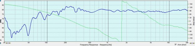
Tuning was supposed to be 60Hz in modeling, but measured at 50Hz. Not really sure how this happened. I only have the dinky supplied washer and bolt that came with the PRs attached to the mounting hole. Maybe the Mms on these units was higher than spec, or the volume somehow is larger than modeled- and I know if anything it's less volume. This yields an F3/10 of 80/42Hz, and that is not really all that bad. Bass sounds great for a 4" design.
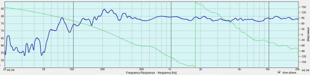
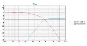
Initial measurements showed a dip at 718Hz and 150Hz. I knew the 150 was likely floor bounce, and ignored it. Modelling the highpass cap doubled indicated that the higher dip might fill in, and it was still present off axis. After this complying modification, I measured higher from the floor, and the dip shifted to 525Hz. The 150 dip disappeared. However, the HD is still good and the upper dip is gone. Fullness was perceived as better on the bottom of the midrange than before. Xover points became 900/4k Hz.
I'll have to separate this in a few posts to get it all up here...
Thanks for looking!
Wolf
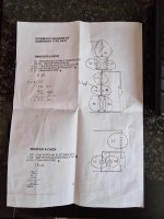
Edit: The purple dims in mm in the drawing are for supposed acoustic Z offsets. These do not represent the dimensions of the drivers.
 IMG_20230902_120337.jpg556.5 KB · Views: 162
 IMG_20230902_120323.jpg465.2 KB · Views: 186
 IMG_20230902_124047.jpg481.9 KB · Views: 169
 IMG_20230902_120313.jpg435.3 KB · Views: 188
 IMG_20230902_120257.jpg464.6 KB · Views: 190
 IMG_20230901_121324.jpg489.4 KB · Views: 219
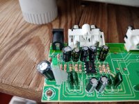 IMG_20230901_121336.jpg452 KB · Views: 182


 )
)