Doubt solid electrolitic capacitors

Do solid electrolytic capacitors in electronic circuits also present problems due to disuse when electronic devices remain unplugged for a long time? Do solid electrolytic capacitors also require at least 1 hour to reforming electronic devices to avoid failures due to disuse?

I turned on a device I have and it has solid electrolytic capacitors but I only turned it on for a maximum of 30 minutes

Looking for working Kenwood TA2040 IC chips

I know this is a long shot but I am looking for some working TA2040 ICs
If you have a severely cosmetically damaged Kenwood Basic M1A or a Kenwood 880SD that still works I can take it off your hands!
or just the chips, either one pair or 2 pairs.
or if you know of a proven supplier of new or pulled TA2040's
contact me here

John

Attachments

  • IMG_20231108_174342.jpg
    IMG_20231108_174342.jpg
    187.4 KB · Views: 85

Trying to build a +/- 18V power supply for hypex DLCP, please help

Hi all,

As the title says, finally nabbed a hypex DLCP after years of wanting one but the smps by hypex seems to be out of stock everywhere.

The unit requires a +/- 18v input (plus ground/neutral rail)

Please bear with me as I try to explain myself, I'm no electrical engineer!

So my ill thought out plan was to buy an 18v AC wall wart, run it across a pair of rectifiers to give me a +/- out, add some smoothing caps then voltage regulators and fingers crossed have a reasonably stable supply.

Now I've just tried to build this, step by step measuring PD across terminals as I went to make sure I was achieving what I expected.

First stumbling block was realising I didn't have a 'neutral' rail. I figured that this could be either rail as the actual difference in potential was what mattered. (Please can someone confirm my understanding is right on that one)
Before building anything AC voltage Was measured out of transformer at 22V (iirc), which seems about right for a hand held multi-meter, assuming it's reading peak to peak not RMS, or somewhere in between.

Next I attached rectifiers in both directions to one rail and measured the DC voltage between each and the nominated neutral rail. This measurement was satisfactory (I want to say it was low as I was expecting that with what I thought would be a half wave rectification, it may have been 18 or 22v).

Once I had an identified + and - output I used 63v 1000uF caps to smooth, connecting polarity so neg leg to neg output for first cap, next cap was other way round, both connected to nominated neutral rail.

This is where I should have stopped, as the voltage measured at 30v.

Rather stupidly I carried on trying to build my PSU and put the VRMs in place (I have 18v 1A regulators in both + and - variaties). Things went wrong, when I connected the ground pin on the positive regulator to the nominated neutral rail there were very small visible sparks, this happened twice and the third time no sparks and I soldiered on. The regulator rapidly got very hot and burnt my finger. I unplugged the wall wart and pulled the bread board appart.

So here's my questions;

I believe my mistake was carrying on past the warning sign of 30v readout. I think what happened is the +/-AC output when rectified gave me a peak to peak output of 36v, resulting in a far too high input voltage for my regulators, hence not working.

So I'm thinking I need to get a much smaller AC wall wart, maybe closer to 12v AC, and some heatsinks for my poor regulators!

Can someone with a bit of knowledge please advise me;

- is my general approach ok?
- is my fault finding correct?
- What AC voltage wall wart should I look for to achieve a stable 18v output after VRMs without requiring too much trimming

Thank you.

Very Loud Click electrical interference

Hi, can anyone help.

Been getting a loud click through speakers which I thought was mains borne as volume didn’t change. Sounds every bit like an old fridge or old thermostat.

I have now tried filtered mains block, transformer based mains conditioning, turned amps 90deg and swapped XLR cables. Nothing has made any difference. I manually got cent heat to turn on/off but didn’t make a sound. Gonna unplug fridge next.

However, thought would ask the knowledgeable people on here what else I can do to track issue down and what I can do to get rid of the noise. Dog hates the noise so guess the click goes into his sensitive hearing frequencies so really need to fix.

Many thanks

John

Fluorescent display with fixed brightness (need variable)

Is there a quick way to dim the brightness on a fluorescent display? In may case, a late 1980s vintage CD player. It has just the factory setting, which is a bit too much.
I would not mind, say, a variable pot, or a two- or three-position switch, or even just turning it off as in the case of some purist audiophile gear.
As I recall, FTD ( fl) displays run on AC at roughly 30 vac.

Considering a DSR1 build in F150

2017 F150 with Sony. Currently have Maestro AR and Kenwood XR600-6DSP powering Hertz Cento Pro 6X9 components active and 5&6 bridged to the factory sub. While it sounds good, I think the Kicker Key that I had in my Silverado running active front with Infinity Kappa's sounded better.

Thinking of taking out the AR/Kenwood and going with a DSR1. Send channels 1&2 to the Key and adding in a Mille Pro 3" mid in a speaker pod, probably send 500hz and up to that and the tweeter by bi-amping the Key. Then use my JL XD700 for the front midbass in the door and the rears, And add my JL 10W1 under the rear seat.

Am I crazy to do this?

I can live with what I have and wait for the Audison AF C8.14 amp to be compliant with the AR module or perhaps the Arc Blackbird.

Technics SU-V8 opamps replacement

Hello. I was given this amplifier and i want to replace the opamps.

Phono stage had a JRC4559DS (service manual has NJM4559DS)
Tone control had a JRC4558D (service manual has NJM4559DS)
Super bass had a JRC4558D (service manual has AN6552)

Can i replace all of them with NE5532P ?I have access to this opamp at the moment.Has anyone tested these opamps with this amplifier?how is the sound experience compared to the originals?


Quote Reply

Report Edit
  • Like
Reactions: thisusername

help with transformer volume control

i built a tvc using 2 sowter 9395 and 2 elma 04-1133 24 position switches, i wired as per the attached sketch, however i think ive made a basic error as i get no output.

can someone give me some guidance with the wiring.

I have used the orange +6db primary tap as the signal input from RCA
Primary red is going to the RCA earth in tab
secondary grey is going to the RCA earth out tab
all the secondaries are going to the switch starting blue/yellow 0db connected to the switch tab when the switch is rotated to the extreme anticlockwise (ie zero volume).
the centre switch tab is going to the RCA signal out

thanks

Attachments

  • IMG_7089[1].JPG
    IMG_7089[1].JPG
    186.1 KB · Views: 73
  • tvc.pdf
    tvc.pdf
    8.6 KB · Views: 76

Mu Follower grid voltage design questions

I am building a mu follower with a 31 tube as v1(lower tube) and 12GN7A pentode as the follower. this stage will drive a E80L triode strapped. I am trying to understand the 12GN7A pentode operating point. I've studied Alan Kimmel's pdfs and looked at Triode Dick's designs. My question is, doesn't the follower grid 1 get too high of a signal to operate properly? What is going on here? Please help me understand this! I can share my schematic if that helps.

Thanks!

KEF Concerto SP1004 DN12 crossovers with different mid (B110) phasing?

Many years ago I constructed a version of the P Atkinson Mini-Line Tranasmission Line speakers, using a T27 and B110 with a WilmsIow Audio crossover, which I regret getting rid of. I am now experimenting with making mini transmission line using a T27 and a B110 in a sealed compartment, with a second B110 in a separate compartment feeding a 1/4 wave length transmission line. For this I am using a Falcon 33Mc crossover, which I purchased for Concertos, which was unused in the end.

The spekers so far sound great in the mid and base regions, but are uncomfortably shrill at the very top end, and I am therefore looking at what changes could be to the crossovers. I also have several DN12 crossovers, and there are two versions with different phase configurations for the B110 !!

I had previosly contacted Falcon to query the phase arrangement on the 33MC and they replied that the B110 should definately be out of phse. However, before I start adjusting crossovers, I wondered what DiyAudio members thought was the correct phasing on the DN12 crossover.

I do not have test equipment and so have to do everything by ear, which is not helped by the aging process of my hearing.

Any help much appreciated

Hybrid GU29 parafeed power amplifier

Hello everyone, this is my first thread, I just finished experiment built gu29 hybrid amplifier. This is the first tube power amplifier I built. For the output transformer I used a regular toroid power transformer because the output transformer for tube amplifiers is very expensive and hard to find in my area. This amplifier circuit is a combination of several circuit parts that I saw in this forum and on the web. I'm just an ordinary hobbyist, so I only have a multitester and a cheap pocket oscilloscope, so I can't measure the frequency response or THD of this amplifier, combined with my 6p1p preamp, this amplifier sounds good (according to my ears), the bass sounds solid and deep like solid state amplifiers. So, according to experts, can this amplifier circuit still be improved and optimized?

Attachments

  • IMG_20231208_104936.jpg
    IMG_20231208_104936.jpg
    542.8 KB · Views: 444
  • IMG_20231205_171337.jpg
    IMG_20231205_171337.jpg
    387 KB · Views: 271
  • IMG_20231205_171327.jpg
    IMG_20231205_171327.jpg
    559.1 KB · Views: 167
  • IMG_20231126_195632.jpg
    IMG_20231126_195632.jpg
    543.7 KB · Views: 162
  • IMG_20231122_195711.jpg
    IMG_20231122_195711.jpg
    655.3 KB · Views: 266

TC9 Array for PA system by beginner

Hello and thank you for this great resource.

I have read many TC9 Line array posts but still possibly not enough. I have some questions please:

I want to make a PA speaker using 8 of the TC9FD18-08 and a sub, trying to avoid complexity where possible.
Yes, I'm trying to achieve vaguely similar to a BOSE L1 Model 2 system on the cheap! I realise this maybe doesn't count as an array so forgive my use of the term.

1. Is 8 drivers going to be enough to play a medium sized pub with guitar and vocals? (with a 12" sub).
-I'm happy to get more. Does the 83.5dB per driver figure get better in an array?

2. On the front baffle side of the box, can I simply lay the drivers onto wooden runners and just butt them together where they collide, and just seal where they butt together? They'd be close together that way no? I realise this sounds like blasphemy!

3. Inside the box, If I were to lay-in length-ways, angled bead on 2 adjacent sides, would this (with stuffing) be a simple way to help with internal reflections? Imagine say a shallow roof shaped bead all the way along. Is it Ok reflections-wise to have a flat side with a slightly roof shaped side opposite?
-or should I lay these on all 3 sides? or something else?

4. Considering I'm only aiming for P.A quality, do I need to worry about the speakers interacting? e.g RCF EVOX 8 don't bother isolating their 8 drivers..?

5. Chris661 had problems with this design creating too much HF at high distance and tamed it using a Low pass XO on some of the drivers. I'm guessing I will have this problem too. Can anyone guide me on how to make a low pass XO? I should probably message Chris!

6. Another PA array guy called Peter Pan angled his drivers left and right in the column. Would this help with the 'too much HF thing' above and negate the need for a XO?

7. Given the specs of the above speakers, If I were to assume a real-world figure of say 20 watts a driver (x8=160W), is the AIYIMA A07 Max in bridge mode going to be enough to drive them? They are quoting 300W with 48V 5A supply which may be optimistic!

8. The sub will hopefully provide a HP OUT of about 150Hz which I will feed to the Aiyima. I'm already starting to wish I'd bought an amp with treble control...
-Any thoughts on this please?

Any help gratefuly received. I have tried to provide links wherever possible. Cheers!


Quick question about active crossover

Hi, I m building a pair of speakers and I wanted to bi-amp them, so I need active crossover, Rod Eliott's project 123 "catched my eye", I can not buy the PCB's where I live so I designed it myself ( at least tried ).
Besides being a bit crowded ( wanted to make them as small as possible ) , any layout problems ?.

Please take a look.

Cheers, Bruno.


Link to article https://sound-au.com/project123.htm

Attachments

  • RodElliott.JPG
    RodElliott.JPG
    36.3 KB · Views: 170
  • V1.JPG
    V1.JPG
    101.3 KB · Views: 177

Stereo angled RCA breakout boards

Hi guys,
Does something like this exist? I’m using the chasis of an old pioneer preamp for my own diy preamp and would like to desolder and reuse the RCAs present in the old board (see attached picture) , but at the same time would hate to solder wires directly to the rca pins, so a breakout board would be great to use. Searched everywhere without luck. Thank you!!

Attachments

  • IMG_7010.jpeg
    IMG_7010.jpeg
    381.8 KB · Views: 105

98 x Vishay IRFP240 and 9240 on reels - same batches

Realizing I won’t have time to match these up for own use and sale, I am posting 2 x reels of 240’s and 9240’s for sale.

Asking 200 USD plus shipping. I paid approx 260 dollars, and had to look for a while to find equal lots at the time, so I guess this is not the worst deal out there.

In total I am selling two reels of N and two reels of P channel mosfets, 25 in each reel. I used two 9240’s for my F2J, so there are only 48 of them left, and 50 240’s.

All P channels are from the same lot (see pics), and the same goes for the N channels. Sourced from Conrad and Digikey. 240’s are PBF, 9240’s are old school leaded 🙂

All devices unused.

Attachments

  • IMG_0531.jpeg
    IMG_0531.jpeg
    603.4 KB · Views: 88
  • IMG_0535.jpeg
    IMG_0535.jpeg
    387.2 KB · Views: 84
  • IMG_0534.jpeg
    IMG_0534.jpeg
    554.7 KB · Views: 85
  • IMG_0533.jpeg
    IMG_0533.jpeg
    479.8 KB · Views: 84
  • IMG_0532.jpeg
    IMG_0532.jpeg
    514.4 KB · Views: 92
  • Like
Reactions: Dennis Hui

For Sale OYAIDE DB-510 Coaxial BNC Cable 75 Ohm Silver 1m

Bought May this year from official retailer. Invoice Copy Will be provided. 1 Meter both side bnc 75 ohm factory terminate. One of the best Digital cables around. Price new 303 Eur sell for 175 eur plus shipping in Europe. Original box available. Tomorrow Will post pictures

Attachments

  • IMG20231118084715.jpg
    IMG20231118084715.jpg
    508.1 KB · Views: 143
  • IMG20231118084728.jpg
    IMG20231118084728.jpg
    400.1 KB · Views: 136
  • IMG20231118084607.jpg
    IMG20231118084607.jpg
    1,006.7 KB · Views: 153

Behringer EP4000 amp

I have one behringer ep 4000 that has blown few outputs 1943 and 5200 and both 50n06 on one channel do to excessive heat (cooling fan failure).I replace all components and check the other channel all was ok.the time for test work both channels ok (on oscilloscope with 1khz signal) for few minutes.

Then the god channel starts rise temperature on R65-62-66-67-68 and gets really hot. After that the waveform is distorted and the signal led and clip led is on if i turn the pot to the right no more than 10 o clock and no signal at input.If the pot is at 0 all way left the leds stay off.

The repaired channel it works normally.doing detailed check again and found nothing broken.Change all output devices one by one to be sure there is no defect.No luck the channel have the same behavior.

Any tips where to look-check?

Thanks for any info.

Switching bench power supply problem

Hi, I have one of these bench switching power supplies. It delivers up to 30v and 10A. The problem is that when I set it, let say 20V and a tiny amount of current, let say 50mA, when I shorten it, at first a big spark jumps and several amps goes and after that reduces to 50mA. Is that normal, as it burns my components once I touch them? If it's not normal, in what section to search for the problem? Anyone had a similar problem? Any direction is welcome. Thank you very much

Attachments

  • IMG_0578 copy.jpg
    IMG_0578 copy.jpg
    321.2 KB · Views: 94

What multichannel audio interfaces are ACTUALLY multichannel

Hi guys,
I've gone through 3 audio interfaces trying to find one that does what I want, have a 4 channel output from a 4 channel card, not twin stereo.

Focusrite 2i4 2nd gen - This worked, you could set it to have front and rear left and right, all 4 channels as a single device, but it has no thump protection and i fear for my tweeters every time my pc goes into standby, it also had awful noise rejection

Motu M4 - Loved everything about this, but the outputs were 2 sets of stereo outputs, which is not suitable for my needs

UA Volt 476 - Loved this unit too, but same problem as above, despite their videos saying that it has 4 discrete outputs on the 4 channel outputs

Sound blaster AE-9 - Has the channels I need, but noise rejection is absolutely non existent and makes my speakers sound like a 90's modem when i scroll a website, also chintzy that they used different dacs and opamps in the main 2 channels to the rest

I looked at some of the other options, like the clarett+ 4, but that has thump protection only on 2 of the 4 outputs, why cheap out like this focusrite, this is supposed to be your "good" line!

I want something that's NOT rack sized, and around £300 or less would be great.

And no, running voicemeter or some other routing software to create a virtual multichannel card is NOT suitable for my needs.

thanks in advance, Tim

ChatGPT ideas about amplifier design

An LTP, or Long-tailed Pair, circuit is a type of circuit topology that can be used in amplifier designs. It can be used to convert a voltage feedback scheme into a current feedback scheme.

In a typical voltage feedback circuit, a small portion of the output voltage is fed back to the input and compared to the original input voltage. The difference between the two voltages is used to adjust the gain of the amplifier.

An LTP circuit uses a pair of transistors, with one transistor connected in a common-base configuration and the other in a common-emitter configuration. This circuit topology allows for a high input impedance and a low output impedance, which can be used to convert the voltage feedback to a current feedback.

The current flowing through the common-emitter transistor is proportional to the input voltage. By using the current flowing through the common-emitter transistor as a feedback signal, the circuit becomes a current feedback amplifier, which allows for a faster response time and better bandwidth than a traditional voltage feedback amplifier.

Is a port useful if one doesn't need to extend response in the low range?

Hello,

I guess this question might sound strange to experienced readers: would it make sense to set a port in an enclosure if one doesn't need to extend the frequency response in the low range? Could a port have a pure "pressure equalization" function which would bring other benefits? Which ones? Then, would it be designed in a different way than an usual port (with a smaller section maybe) ?

Thank you for enlightening me!

Turntable build - Thoughts?

Hey

I'm in the proces of putting together a semi-DIY turntable. Wondered if you guys have any thoughts on the plan so far. Here it is:

Turntable:
I'll probably go with this aluminium / tungsten platter with a maglev bearing. It's also used in Troels Graversens build if you've seen that before. This is quite a lot cheaper than most alternatives (considered VPI platters and such, but their prices are just outragous)

- https://destiny-audio.com/products/...maglev-bearing-for-diy?variant=40628555677807

Drive system (will be seperate from plinth):
Valhalla electronics Zeus controller and a premotec 31813 motor. I'm pretty sure this motor control system (with a tachometer) has been around this sub before. I believe that the guy building these is the user Scobham, if i'm not mistaken. I'm still looking for a pulley with the correct dimensions (40 mm) - asked a Nottingham distributor for their pulley dimensions as they use a similar system, but no answer yet.

- https://www.valhallaelectronics.com/product/zeus-controller/

Tonearm?
In doubt, maybe a Rega rb880 or a Clearaudio Verify. I'm not too comfortable buying used tonearms.

Plinth:
Honestly I'm probaly gonna do layers of plywood with an outer layer of some pretty wood. I'm considering using an mdf - aluminium - mdf combo (has been discussed a lot on this sub before), but i'd have to finde someone with a CNC machine. The plinth is gonna be the last thing i make, I'll build a temporary table just to see everything work first, and then test out some material.

Replaced binding posts, but something has gone wrong, now/low output - Please help

See attached schematic.

I started off by removing the barrier strip from the right channel, and installed two binding posts. I connected the binding posts to the 8 ohm transformer tap, and the 0 ohm tap, along with the (feedback?) wire that goes from the 0 tap back to the junction of R9 and R14.

When I first completed the work, I had output, but it was quiet. I've since fiddled around, trying to take measurements, and observe different connections. I fear I may have caused some further problem, because now I get voltage across the posts, but it drops to zero as soon as I connect a load (and I get no sound from the speaker).

When I was fiddling around, I occasionally observed a high pitched whine coming from the output transformer when I connected the ground probe of my scope or meter to the 0 ohm post. I also observed very high voltages when measuring between the 0 and 8 ohm posts, on occasion. Further, on some occasions touching the 0 ohm tap to the (feedback?) wire caused my source equipment to fritz out.

I have checked and rechecked the wires I'm using. I'm utterly baffled why any of this should have occurred. The posts may have been shorted to the chassis on first assembly, but they are not now.

I'm sure there are many bad things I may have done. I would appreciate suggestions on how to test and verify what I may have screwed up.

Attachments

XSD Speaker Crossover and Waveguide GB

edit July 3, 2022: please get 8ohm PRV 5MR450NDY; get the GRS PT2522-4 (open back no cup) planar tweeter, and the GRS 6PR-8 8ohm woofer (8x), per speaker.

This is a group buy for the XSD speaker crossover (XO) and tweeter waveguide discussed here. I think it’s best to keep the original thread for the technical discussion and this for the logistics of the GB. The XSD is 91dB sensitive open baffle dipole speaker with an 8x 6.5in woofer array for bass, a premium 5.25in low distortion high sensitivity midrange and a planar membrane tweeter. It is one of the best sounding speakers I have ever heard. The dynamics are staggering and the distortion is extremely low. You have to be careful how loud you play it because it’s hard to tell how loud it is based on distortion. The dipole nature of the speaker gives it a natural presence that simulates a live band very convincingly. The speaker plays all genres of music well. Especially complex orchestral symphonies and heavy metal that often challenges speakers not capable of nuance or dynamic range. I have voiced it to sound natural and engaging. The midrange level is adjustable through a simple resistor change if you like your vocal presentations more or less forward. The treble is light and airy and since the midrange handles the majority of the telephone band from 500Hz to 5000Hz, the speaker has a coherence and spatial imaging of a point source full range speaker.

The XO Kit will include all the resistor, capacitor, and induxtorcomponents plus a schematic for you to assemble the components to generate a passive XO that provides the following filters at 470Hz and 4700Hz. You will need to follow the dimensioned speaker plans (sketch) which I can provide via email if you PM your request. Note that this is a commercial design so I have been given special permission to provide the XO kits with the requirement that you do not share the schematic or post it publicly.

This is my prototype build:
1652723830217.jpeg

1652721956517.jpeg

Renders so you can visualize it in a lighter color scheme. I think satin piano white would be a good look as well:
1652723205588.jpeg

1652723227583.jpeg

Measured harmonic distortion:
1652721997602.png

Predi
1652722017277.png

Impedance is 4ohms nominal but well
1652723275708.png


I’m also providing a custom CNC’d aluminum waveguide and bezel for the GRS PTT2522-4 tweeter. It has a satin bead blasted black anodized finish. It’s more than cosmetic as it improves the bandwidth extension, lowers distortion, and smooths the output in addition to providing a nice way to mount the tweeter.

The XSD crossover BOM was developed using quality components. All Mills 12W MRA12 non inductive resistors for the mid and tweeter, and 20w non-inductive wirewound 1% Dayton resistors on the woofer shelving filter. Iron core 18ga inductor for the woofer, 18ga air core for the midrange, and 20ga aircore for the tweeter. All capacitors are MKP film (mix of Audyn Q4 and Dayton DPMC) plus one 100uF 400v bipolar electrolytic. You are welcome to upgrade the electrolytic to a film cap on your own if you choose.

The XO will consist of:

6 Mills MRA12 12W resistors
2 Dayton DPR 20W 1% non-inductive resistors
8 Audyn Q4 MKP caps for midrange and tweeter
8 Dayton DPMC MKP caps for midrange and woofer
2 100uF 400v bipolar electrolytic caps for woofer
2 20ga aircore inductors for the tweeter
4 18ga aircore inductors for the midrange
2 18ga ironcore inductors for the woofer

Here is a photo of an earlier crossover with an electrolytic bipolar cap and film cap bypass for the woofer to give you an idea of how I laid things out:
1652723960239.jpeg

Here is photo of my prototype XO (with some optional upgrades like all film caps for the woofer section) - the quality of the parts on the Kit offered here are as equivalent otherwise and even better since you will receive all non inductive resistors like Mills MRA and the large 20W Dayton for the woofer shelving filter:
1652722884431.jpeg


Edit Aug 14, 2022: here is a XO built by member Plott using the actual parts from this GB. Very nice work.
xo_20220814_2-jpg.1080909


I am offering the XSD XO Kit (stereo pair) as group buy or $375 - majority of this is for the cost of the parts and small amount for my effort to assemble the kits. If you want the CNC waveguides, those are an additional $68/pair.

Photos of the waveguide:
1652722692360.jpeg

1652722706887.jpeg

1652722727269.jpeg


This waveguide is also very handy if you want to use this tweeter in another project as it’s a superb tweeter for many applications.

You can have a listen to the speaker here (recorded with my phone):

Login to view embedded media
Here is the GB interest list so far. Please add your name, qnty of XO kits and WG pairs, and country if you are interested.

Shipping is not included and will depend on your location and be auto calculated through my Etsy shop. Typically circa $15 in USA. Overseas will be higher as there 8 inductors and some large film caps plus aluminum waveguides. My guess is circa $35.

Name / #XO’s (pair) / WG’s (pair) / Country
____________________________________
Bryguy / 1 XO / 1 WG / USA
JHClark / 1 XO / 1 WG / USA
32y0 / 0 XO / 1 WG / Australia
bloqhed / 1 XO / 1 WG / USA
  • Like
Reactions: tamra

what amp power do I need?

Hello, friends!
I'm planning my own project, which will have 2 full-range speakers of 20 W RMS (4 ohms) each and one subwoofer of 150 W RMS (4 ohms). I don't plan to listen to music at full volume. So I plan to use DIY 2.1 amp (25+25W and 50W). But will a 50W sub amplifier have enough power to drive 150W subwoofer? I understand that it won't play loudly. But will amp fail? Or will it cause too much distortion? Or just will play without perceptible bass?

Thanks for help!

PS. I can't purchase a less powerful subwoofer and have to work with what I have.

Do I understand the output coupling capacitors in this preamp properly?

See attached schematic.

1. I see that the output capacitor filter is made up of three capacitors. I've seen a big cap crossed with a small one, by what's the 1.0 part for?
2. Am I correct that C7/C9/C11 forms an RC filter with R43 and R45 (and likewise for the opposite side of the amp)?
3. I've been told output capacitor values don't matter much. If I'm right about #2, I worked out that 1-2 uF changes in total capacitance would have a negligible effect on the output. Again, please check my work?

Attachments

  • LS5 Schematic.png
    LS5 Schematic.png
    314.9 KB · Views: 240

help me choose Mordaunt Short 906i or MS Aviano 6?

got choice of 2 sets of floor standers, used to have a pair of MS 206 and loved them.
Think both of these are very good and also quite similar.
Anyone have either or both ?
Anyone want to throw their tenpeneth in on which to choose. 🤔
Just remembered and to confuse matters further i also have the choice os some monitor audio ma14 mk2s also.

Moving to a detatched house again soon, so i can Whoomp it up a bit 😆

Custom Printed Acoustic Fabric for DIY panels?

I have some printed art on canvas (60.5"H x 20.5"W wrapped, etc) that I enjoy, and I would like to replace them with DIY acoustic absorption panels. The original art files are on hand.

Can anyone recommend a hobbyist or small businesses that will print on UV stable acoustic transparent fabrics for this purpose? I have my doubts that my local print shops will have any acoustic fabric for this purpose.

tube amp hybrid, disconnecting filter circuit from headphone out

hi, I'd like to disconnect the cap used for filtering out the 'papery sounding highs' from the tube preamp, that is probably connected to the headphone out. That way I can connect it to my computer interface and use my impulse responses. Here's a schematic, any help? The cap or caps are on page 2, probably somewhere bottom right. Is it c1? Thanks!

Attachments

Push Pull Rectifier Trouble

Hi, and thanks for taking the time to read this post. I am a neophyte, so please excuse my ignorance.

I have a Knight KG-400, which is a push-pull 32W integrated amplifier consisting of 4 6bq5(s), 1 GZ34, and 6 12ax7(s). The amp currently has no playback output, and some of the 6 12ax7(s) are not getting power. So I am stuck at pin 8 of the GZ34, which should be about 390V. With all the tubes in, I'm getting like 35V. If I remove tube 1, the 12ax7 phono tube, the voltage jumps to about 320V. In the current state, when I turn the amp on, I just get a slight hum - my dim bulb tester does not get real bright, nothing is burning, etc. Where is the voltage on pin 8, and how do I go about troubleshooting this?

tweaking pedja's Diamond differential I/V

so i just got done building DDNF as described here and am very impressed with the sound.

https://www.diyaudio.com/archive/blogs/dvb-projekt/attachments/399d1305647776-pedja-rogic-s-discrete-diamond-non-feedback-i-v-stage-out-production-pedja-rogic-ddnf-iv-stage.pdf

in the document he's talking about adding ccs, and i'd like to know what else that can be done to this to improve the performance.

Tie the Transformer's CT as vise-versa

Hello.

I'm currently designing my own linear power supply.
Everything seems going well, but there is one thing I concern about.

Can I make the center tap of transformer with tying pins of fall apart to each side away?
The datasheet of transformer I used tells that I have to tie 9 and 10 pins to get series output, but unfortunately the PC board layout currently designing by me may not allow me to do that by some reasons, so I decided to tie 7 and 12 pins to make the center tap(GND).

ampproject7-transformer_connection_diagram_231123_103233.jpg


Would it cause a problem or perfectly trustable?

Here's the datasheet of Transformer : https://catalog.triadmagnetics.com/Asset/VPP36-1560.pdf

I'll look forward for your opinion.
Thanks for reading.

Weird behavior today (invalid SSL certificate issue)

Hi,
Access to site have been blocked this afternoon: i kept on seeing 'temporary unavaillable' message and when i managed to have access i got a message telling me the site is not secure and had to force access.
I've got a warning symbol before the site adress too.

I'm on Samsung tablet, Android 8.1.

Another weird thing: i tryed a google search and got results which were impossible to load ( site is temporay unavailable...)

  • Locked
FREE 16-channel CRESTRON CNAMPX-16x60 amplifiers! Local pickup only, MI USA

I'm still trying to clear out some equipment before a big move and I have three amps that I would be willing to give away for free, with local pickup. These amps weigh 90 pounds, so shipping is a no go. Pickup near Lansing Michigan.

Amps are Crestron CNAMPX-16x60. Please use Google for complete info. The amplifier modules used in this amp are made by ATI. Each module is 2-channels, and you can disassemble the amp and reconstitute these into 2*N channel amps as needed. A fun project (I did this with two of these amps already).

SORRY ALL ARE GONE NOW

Rubicon 1002 thermal runaway

I'm having the same problem with my Rubicon 1002. It's runs hot at 4 ohms mono and seems to draw more current then it should from my overkill 240 amp alternator. Did they mess them up at the factory and put in an incorrect part on the board and it's a must that it be corrected?

I have a Rubicon 502 at 4 ohms stereo running my components and it stays ice cold, I guess because it's doing less work then the 1002 on subwoofer duty.

Reading other threads it seems like less than ideal or possibly even the wrong components were used on the 1002 board that causes thermal runaway and excessive current consumption.

These amps are new, just took them out of the box for my 2020 build.

Since nothing blew yet and they appear to be functioning normally, can I just take the amp to some electronics repair and have the bias turned down, or does something more drastic need to be done like replacement of less than ideal board components?

Aiwa AP-D50 photoelectric end sensor info?

I'm interested in this non-contact sensor.
Can anyone tell me more about the design, would putting better (different) resistors on the board be of any benefit? There are 4 sensors with domed lense like faces on the hole side. The two bottom sensors or emitting diodes which sit in a space with a tiny hole under them (just like the top two) have red marks on the top, bottom and sides of the sensors. The top two don't have these red markings. Does anyone know why the diodes have red markings? I'm trying to source in PN150 and LN55 but they appear to both be discontinued, and I can't find any old stock for sale. Are there any components that would function as substitutes if I wanted to put all new components in a backup end sensor board?

Screenshot_20231203_000113_eBay.jpg


Screenshot_20231209_012509_Gallery.jpg


Basically I restored a D50 that was in a very bad state with every fault going. Towards the end of the restoration, after the first test runs when the motor was repaired, I realised it sounds quite incredible. I was so shocked that I decided to source a backup end sensor, as it seemed the most complex part.

Thanks for any advice!

Kicker HS10 Hideaway

Guys I need help! I don't know what I'm doing even though I'm watching videos etc. Ok, 2015 Silverado 1500. 2 hs10s. Powered separately but to battery, remote both together, stock deck with a aftermarket device I plug into deck then plug deck into device. Device has two rca jacks, line out converter to left and right subs. Tonight I tried the right sub tying into rearspeaker wire. It sound horrible. Some people say I need a aftermarket deck? I give up! Lol

For Sale Salas SSHV2 HV Shunt Regulator Boards

I bought 4 boards of the Salas SSHV2 shunt regulator in a group buy from Tea-Bag, the board for €15.00/each. Boards are blank / unused. I no longer need the SSHV2 and offer it here. The price does not include shipping and PayPal fees. Preference and preference are buyers from the EU, shipping outside the EU is possible but takes a little longer. Shipping from Finland.

Regards Finwbu

Attachments

  • IMG_20230310_073135.jpg
    IMG_20230310_073135.jpg
    372.1 KB · Views: 258
  • IMG_20230310_073140.jpg
    IMG_20230310_073140.jpg
    307.5 KB · Views: 215
  • IMG_20230310_073239.jpg
    IMG_20230310_073239.jpg
    453.6 KB · Views: 187
  • IMG_20230310_073241.jpg
    IMG_20230310_073241.jpg
    364.3 KB · Views: 182
  • IMG_20230310_073242.jpg
    IMG_20230310_073242.jpg
    333.5 KB · Views: 190
  • IMG_20230310_073243.jpg
    IMG_20230310_073243.jpg
    379.1 KB · Views: 216

JLH Mosfet Power amplifier construction thread

Hello

I have made many of these some years ago .. and have learnt very much by experimenting and seeing what other people have been doing. I thought I would dedicate this thread to some projects that I have in the pipe line for this amplifier. What has triggered this you may ask .. well I had a chance to listen to a couple of units that are still working and in fine fettle, and I was really impressed with the sound quality and the stability of the design and remembered how impressed I was when I first completed my first 2 units in the late 90's ....

so please enjoy and add your comments constructively .. 🙂

FAST/WAW with a rear firing tweeter?

Just sitting here thinking about the mix/mastering process and the typical use of shelf filters to add 10khz and up content to recordings which develop the sense of air and the acoustic space we’re all accustomed to. For HF drivers without a horn lens, these frequencies are very directional and if listening off axis, either are too low in amplitude or are riddled with ragged response and break up modes. But what if we used tweeter on the back?…..say crossed over very high around 7khz or so. We could trust the front wall and obstructions to splay the content back into the space, returning that sense of air and space. I’m sure there’s some designs that use this method but I’m just inquiring for those here in the DIY realm who’ve given it some thought or a try?

The Kuartlotron - keantoken's simple error-correction superbuffer

September 2020: PCBs are still available, PM me. Build info/BOM: The Kuartlotron - keantoken's simple error-correction superbuffer

This is the official thread to announce my Kuartlotron buffer. It's based on a 4-transistor Tringlotron-like error correction scheme. If I did my job right, I shouldn't need to describe it here because I've already made a webpage for it:

The Kuartlotron

I started discussion in the Mpp thread originally, which included measurements, theory, discussion and even reviews from Joachim and one of his friends. Note: the schematics in the Mpp thread are pretty but few of them have been built and tested, and they are old versions - see the Kuartlotron webpage instead.

Beginning of Kuartlotron discussion:

MPP - diyAudio

Subjective Comparison of Staccato Audio OSH-DHb Dual Discrete op-amps and Burson Discrete V6 Classic op-amps and their Audio Quality

Staccato Audio has been building op-amps since 2017 and the current form is a hybrid Class A op-amp using the BC560 transistor. In the production process for their “Open Sound Hybrid” (OSH) op-amp, the company uses matching input 2SK209 JFETs transistors from the batch of 1000psc, and adjusts the output current to keep the same load for all three output pairs of 2SK2145. Staccato Audio's manufacturing of high-performance discrete op-amps in Poland is led by engineers Jakub Honkisz, who is the founder and project manager, and Morten Oksbierg, who designs the analog circuits. They also make class A amplifiers.

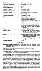
Jakub Honkisz sent 3 OSH-DHb Dual discrete horizontal op-amps for this review. Staccato Audio op-amps makes use of J-FET, in both the input and output stages in combination with a high bias current with low open loop distortion with domination of 2nd order harmonics. The source follower at the output uses an active current source which allows higher output current than the bias current. The highest output Current is ±30mA. Two voltage ranges are listed as the op-amps can be driven to 18V if cooling is sufficient but will need to be dropped back to a maximum of 15V in applications where tight fits and lack of air movement leads too much heat. With class A bias, crossover distortion is decreased in the staccato op-amps. Total Harmonic Distortion is listed in the data sheet as 0.0002.

In contrast, Burson V6 classic has Total Harmonic Distortion of .02 and is not class A. In a previous review, I found the Burson V6 classics to be superior in a subjective listening test to the Burson V5 and OPA627.

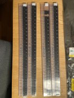
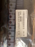
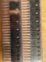
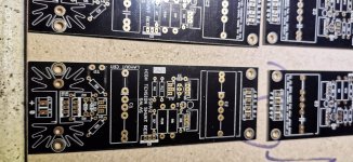
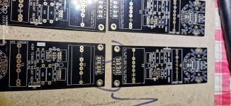
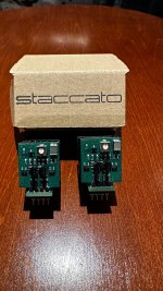
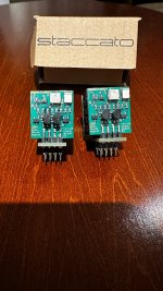
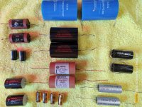
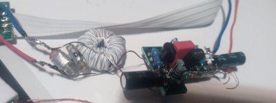
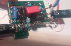
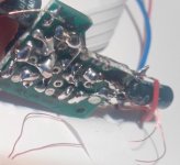
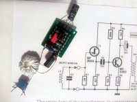
The Staccato Op-amps stand about 1.25 inches high (not counting pins) and are roughly 1 inch on the side and 3/8 inches thick. I was sent three OSH-DHb Dual discrete horizontal op-amps shown below:

1667795991187.png


The Staccato op-amp packaging was good with all 3 op-amps I received in a sturdy box with 3 small boxes in it containing a bag with the op-amp. The legs of the op-amps were secured with foam to prevent bending during shipment. The product arrived from Poland.

box.jpgwrapper.jpgop-amp comparison.jpgop-amp with foam.jpg
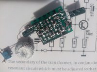
Packaging and comparison of Burson V6 Classic and Staccato Audio Op-amp size

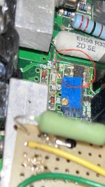
My system is composed of an Asus Gaming Computer running JRiver media center 28 which I modified to up sample all files to 96 KHz which are stored on a Passport external hard drive. I have an external Musiland external soundcard I use with optical out through a glass optical interconnect to a Cyenne 3100 DAC which has three replaceable op-amp sockets. The DAC output goes to a Cambridge Audio CXA60 amp. I have Mordaunt-Short Aviano 6 speakers and a Wharfedale subwoofer.

My dedicated room, specifically built for music, has highly acoustically treated ceiling, walls and corners and a straight equalization curve along the x axis, according to Room EQ Wizard, without any equalization required in the JRiver. To achieve this on axis equalization with only treatment took years of work installing the proper arrangement and rearrangement of bass traps and acoustic tiles.
1667796141732.png

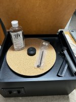
Ceiling acoustic treatment

dac2.jpg

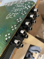
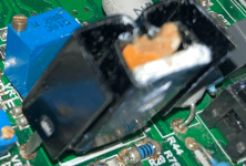
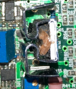
Cyenne 3100 Dac with 3 Staccato Audio dual op-amps

The Cyenne 3100 Dac has 3 removal socketed op-amps. One serves as a combiner op-amp for the DAC. The other two are gain op-amps. The sockets will vary from Staccato Audio discrete op-amps to Burson V6 Classic. Since I only have 2 Burson V6 Classics, they will be placed in the gain op-amp sockets and a Burson V5, similar to the Burson V6 Vivid, in the combiner op-amp socket. I will listen to a playlist of Flac files with a minimum 44.1 KHz and note any sound differences for each op-amp.

I plan to look at the following factors to evaluate the op-amps reviewed: transparency, details, color and texture, and dynamics and soundstage.

Definitions:

Transparency: the sound is reproduced accurately without adding much extra.

Detail: hearing the small, fine sounds of a recording; the most delicate parts of the original sound.

Color and texture: Tone color or texture of a sound is the quality that allows you to separate two instruments playing the same instrument. It is hearing the different layers and harmonies of music.

Dynamics and soundstage: variation in loudness between notes in the spatial sound image presented to the listener.

Tracy Chapman - Fast Car

I begin my review with Tracy Chapman’s Fast Car.” “Fast Car” is a favorite of Harmon Audio. Their site states that this track is not only one of the most beloved ballads of the 1980s, but also has a fair amount of bass that will often cause modulations to her voice on a system where the woofer is driven beyond its limits. It produces a high quality ‘musical’ signal.

All listening tests are listened to with an average of 78 db of sound. The test is not blind since I did not trust anyone to properly replace the op-amps. I am familiar with the V6 Classic sound and the Staccato sound is so unique, it could not be confused by me; so little is lost with a nonblind comparison.

With the V6 Classic the sound was superb as expected based on my past review. Bass is adequate and when the chorus kicks in the drums attack with gusto while the vocal is natural sounding with good instrument separation. The dynamic range from low to high is smooth and natural.

The Staccato OSH-DHb in all three sockets was completely different in character. As expected from the Staccato superior metrics, the sound was much more transparent and less colored. Chapman’s vocal displayed no obvious alteration from what would be expected from the recording studio. When the chorus hits all the drum details are heard clearly, but without an edge an increased clarity often imposes. Bass and dynamic range is impressive with no part of the frequency response seemingly changed for emphasis.

Van Morrison – Flamingoes Fly

This is a lovely love song by Van Morrison which was slowed down and made more palatable on the “Philosopher’s Stone” Cd than the original and disappointing “A Period of transition” cd.

The V6 Classic presented with deep bass, excellent texture with spatially distinct instruments and vocal centered. The vocal and music sounds live with instruments coming from all corners.

The Staccatos provide very deep strong bass. Details seem more defined. It is a more analytic presentation that reveals specifics not found in the V6 Classic presentation. Peripheral details in the respectable soundstage are more pronounced. The midrange sounds less pronounced than the V6, possibly due to an unaltered presentation of the material.

Sinead O’Connor – Black Boys on Mopeds

In this protest song in which O’Connor sings that Van Morrison’s depiction of Madame George and roses during Margaret Thatcher’s reign is a fantasy due to a tragic shooting of a black man on a scooter. It is beautifully presented with the V6 Classic op-amps. During the listening, background vocals echoes can be heard blending well with the lead vocal with a warm tonal quality. Vocals are very wide and breathing is clearly heard during the song.

The Staccato again provides more clarity in the vocals and even allows the sliding of fingers on the guitar strings during chord changes to be clearly heard. These are very transparent op-amps and although the V6 Classics are pleasant sounding, they clearly color the musical presentation at the expense of recorded details.

Beercan – Beck

This is a fun, fast moving tune with a great opportunity to check dynamic range and presentation of texture and soundstage due to the numerous instruments and peaks and lows in the music. The V6 presents the deepest bass heard yet in any recording reviewed. Instrumentation is clear and distinct. As said, the track is very busy musically, but each instrument is heard distinctly while lows, mids and highs are heard clearly with a wide soundstage.

The Staccato presentation, similar to the V6, provides a very prominent bass. The track is very sonically busy, but there is nothing hidden or masked by coloration. The Staccato op-amps seem faster than the V6 with complex musical forms and never seems to lose details with the tempo of the music or busy texture. Details remain prominent and defined without sharp edges, despite the transparency.

Kiko and the Lavender Moon – Los Lobos

This is an excellent song by a great band. The V6 provides good dynamic range with good perceived high frequency response and punchy bass. The soundstage is wide and texturally each instrument and tone can be heard distinctly. Clarity is present in the music, but warm without harshness.

The Staccato Is again clear in presentation. Vocals and instrumentation provide an immersive soundscape with the Staccatos. There is clarity and presence with the percussion with a slightly recessed midrange. The transparency of details lets the listeners know what is heard is uncolored and what likely happened in the studio.

Mr. Jones – Counting Crows


A song about wanting to be Bob Dylan beautifully sung and presented by the Counting Crows. The V6 presents punchy bass and a forward vocal soundstage. Instrumentation is copious but spatially diverse and not smeared but with a smooth warmth.

Staccato op-amps definitely preset a better musical performance than the V6 on the track. The bass is strong, but more rounded and developed. Background vocals are more easily heard and immersive than the V6 as well. Detailed music reproduction is the norm with the Staccato op-amps and their clear, refined and transparent sound is repeated on this track.

Summary

The review favors the Staccato op-amps over the Burson op-amps with respect to less distortion and coloration. They are, in short, more transparent, detailed and with less coloring and masking of timbre with equalization while also maintaining good dynamics and an adequate soundstage which seems to represent an authentic soundstage.

This does not mean the V6 Classics are bad op-amps. They are very pleasant to listen to and may be the choice for those who want a warmer, but less detailed presentation. I will keep the Staccatos in the sockets.

A Few Words on Audio measurements and Discrete Op-amps.

Paul McGowan of PS Audio remarks that a designer does not design a discrete circuit, which is more expensive, when a 50-cent part is available for no good reason. He goes on to state that silicon in wafer form has tremendous benefits in terms of temperature, component matching and speed. However, discrete op-amps exceed in contrast when it comes to heat, ability to source current and design parameters chosen the designers. Staccato Audio’s class A bias is one advantage of these characteristics Paul McGowan mentions.

Some readers are strictly objectivists in reviews of audio. Subjective preferences are considered unscientific and useless by objectivists.

Most people would consider medicine to be scientific, but would be shocked if physicians could only feel a pulse, or listen to a heart but would not listen to client complaints of fatigue, pain or other subjective ailment. Psychiatry as a medical profession would cease to exist if subjective evaluations were dismissed.

With respect to audio, THD is important when evaluating an op-amp as is open loop gain, slew rate, etc., but if several op-amps meet acceptable criteria for these metrics shouldn’t consumer subjective preference be considered? Harman Audio thinks so and uses subjective evaluations of listeners to improve their products with engineers altering products to meet the subjective evaluation needs of critical listeners.

The following information is acquired from the chapter “The subjective correlates of sound level, frequency, and spectrum” as described in Critical Listening Skills For
Audio Professionals
by F. Alton Everest.

An audio engineer has available an impressive array of instruments for measuring the physical
aspects of sound. One is the sound level meter, by which he can readily measure sound pressure
level or intensity as it is also known. Another is the electronic counter, which can faithfully count each cycle of a periodic sound wave and thus determine its frequency. He also has a spectrum analyzer that reveals at a glance the harmonic structure of a complex periodic wave. These instruments and others all operate in the realm of applied physics. They measure only the physical attributes of the sound as it comes to our ears. The response of our ears to that sound stimulus exists in an entirely different realm: the realm of psychoacoustics.

There are no subjective instruments or meters that can give us direct readings of the response of
an individual to different physical stimuli. Each person responds in a different way. The only
way to measure human response to different sounds is by psychoacoustic testing. Panels of
observers or listeners are the very heart of such experiments, and their response must be
statistically analyzed to get dependable answers.

No longer can audio people take the ear for granted. The auditory response to speech and music vibrations in the air must be taken into careful consideration, for human perception is the final link in the audio chain. The frequency response of our auditory system changes with the sound level.

Subjective loudness and physical-sound-level meter readings can only be correlated through psychoacoustical measurement techniques involving human listeners. When you go to an otologist or a clinical audiologist to have your hearing tested, your audiogram is really your own personal minimum audible equal-loudness contour. The frequency response of our auditory system changes with the sound level
.

One way to define pitch is that attribute of sound which, when varied, can result in melody. Pitch is another strictly subjective concept. Pitch is related to the repetition rate of the waveform of sound. For a pure tone, pitch is related to frequency. There is a curious phenomenon called low pitch in which complex tones tend to have a slightly lower subjective pitch than pure tones of the same frequency. In the following comparison, the A note on the piano and the pure tone from an oscillator have been carefully adjusted with an electronic counter to have exactly the same frequency: The pitch of the piano note seems to be slightly lower than that of the pure tone. The presence of the partials in the complex tone has to be responsible for this effect, because the fundamentals of both are pure tones of identical frequency.

The “case of the missing fundamental” casts an interesting sidelight on timbre. Let’s consider three pure tones: 400, 600, and 1000 Hz: There are three distinct pitches, since each tone has its own pitch. Now, let’s see what happens when all three are sounded together: The pitch of the combination is not that of the 400-, the 600-, or even the 1000-Hz tone; neither is it a mixture or average of the three. Rather, what we hear is the pitch of a 200-Hz tone: Now, what is so significant about a 200-Hz frequency? One clue is that 400 and 600 are 200 Hz apart. Also, 600 and 1000 are twice 200 Hz apart. Everything comes together and is understandable if these three tones are considered as harmonics of a 200-Hz fundamental. Thus, the pitch of the combination turns out to be that associated with a 200-Hz fundamental which isn’t there at all! The ear/brain auditory system has it all figured out that only a fundamental of 200 Hz makes sense of these three tones considered as harmonics.

In summary, loudness, pitch, and timbre are subjective characteristics of sound. There are no instruments for direct measurement of these dimensions of sound. The responses of many people in a psychoacoustic type of test are the only way to quantify these factors. Sound-pressure level is a physical correlate for loudness, but the two terms may not be equated. In a similar way, frequency is a physical correlate for pitch, and spectrum is a physical correlate for timbre. But it is imperative that we do not confuse the physical stimulus with the psychoacoustical response.

IRF9610 Heatsink Measures 70-80 Celsius: Is this too hot?

Hi Everyone,

I recently rebuilt an amp with heatsinks similar to the OEM. The heatsink is rated at 20C/W. These were the only heatsinks I could find that fit the PCB footprint. Unfortunately I forgot to align screw holes and I've used a pencil to press the heatsink against the transistor. I used a thermal laser gun to measure the heatsink temperature around 70-80C. Is 70-80C too hot? Is there a target temperature? The IRF9610 datasheet doesn't specify much. I'm thinking about adding aluminum from an aluminum can. Thanks for the help.

Attachments

  • Screen Shot 2022-05-04 at 10.47.50 AM.png
    Screen Shot 2022-05-04 at 10.47.50 AM.png
    247.6 KB · Views: 408
  • Screen Shot 2022-05-04 at 10.53.04 AM.png
    Screen Shot 2022-05-04 at 10.53.04 AM.png
    414.1 KB · Views: 395

big (15") biflex ala Altec 415

Any experience or thoughts out there with the new Greatplains Altec 415-8b or the big EMS biflex or any other large wideband woofer that relies on mid-cone suspension to let the highs radiate from only the inner portion? I'm wondering about things like radiation pattern, distortion at the physical crossover and low level finesse. Any other thoughts? Thanks very much!

Help with improving thermal management: moving SMT transistor above board?

I'm trying to improve the thermal management in the Power Amplifier Section of my integrated amp. There is a particular hot spot I'm worried about. I am measuring 80C+ on the case of a SOT-223 transistor (Q12/112 - ZVP2120G). Is this too hot? This puts the junction near 100C, according to the SOT-223 junction-to-case thermal resistance of around 12C/ Watt. I've calculated about 3/4 Watt (Vds * I) of heat being dissipated. The copper padding area under the drain and PCB thickness are not dissipating the heat quick enough and heating up nearby components, like q19/119 and VR1/101. The rest of the PCB is typically 50-60c after warming up. Another motivator is noticeable sound degradation, when ambient temperatures are above 25C hotter, the amp sounds strained. The main output device heatsinks usually stay below 45C. As a temporary aid I’ve added a small surface mount heatsink on top of the Q12/112 case via thermal tape. This helps a bit (~5C?) but is not a permanent solution. The tape will wear out. I've considered adding a heatsink under the PCB which again means glue that will break down over time. No fans, since they will add dust and I don't want to turn them on and off.

I’m thinking of moving the Q12/112 to a DPAK breakout board and securing that to the main heatsink above the PCB. The heatsinked breakout board will be mounted to the main heatsink via a breadboard - see the attached photo.

In efforts to improve thermal management at the PCB level this setup seems to be adding some noise.

1. An inch of wiring from the DPAK breakout board to the PCB pads.
Will this create considerable noise and or other issues.

2. I plan to connect the heatsink to the Drain which as I understand introduces EMI via the heatsink and can cause other issues. I don't know if these would be noticeable. I figure at best this setup will emulate the same MOSFET , just in a THT package. Or do I electrically insulate with a SIL pad heatsink and connect it to ground? It turns out the heatsink for Q14/114 is connected to its Drain.

In the end will I trade less heat (in the PCB) for noticeable noise and or other issues? This is just one component...

Notes:

I've converted several surface mount power resistors to THT above board to cool down the PCB, positioned other THT power resistors higher above the PCB. My goals are 70-80C junction temperature for Q12/112 at ambient temperature 25C, and PCB temperatures around 50-60C.

ZVP2120G datasheet:

https://www.diodes.com/assets/Datasheets/ZVP2120G.pdf

Breakout board:

https://oshpark.com/projects/SmLNbAES/view_design

Breadboard:

https://www.digikey.com/en/products/detail/sparkfun-electronics/PRT-08808/7387401

Heatsink:

https://www.mouser.com/ProductDetail/532-574502B33G

Stock photo of the amp:

https://www.hifi-inside.com/images/...fier/thumbs/phoca_thumb_l_destiny-1-creek.jpg

Photos of Q112 covered by the current heatsink, silk screen, and schematics attached.

I'm trying to get a perspective and relevant details of the scale of noise or any other issues I might be introducing. The chassis is 3mm thick aluminum which serves as a good heatsink.

Attachments

  • emi-vs-thermal-management-in-moving-a-dmosfet-to-above-board.png
    emi-vs-thermal-management-in-moving-a-dmosfet-to-above-board.png
    109.6 KB · Views: 192
  • hfe_creek_destiny_int_schematics_en.pdf
    hfe_creek_destiny_int_schematics_en.pdf
    3.1 MB · Views: 145
  • emi-vs-thermal-management-in-moving-a-dmosfet-to-above-board.jpeg
    emi-vs-thermal-management-in-moving-a-dmosfet-to-above-board.jpeg
    196.8 KB · Views: 204
  • emi-vs-thermal-management-in-moving-a-dmosfet-to-above-board 2.png
    emi-vs-thermal-management-in-moving-a-dmosfet-to-above-board 2.png
    106.4 KB · Views: 209
  • IMG_2383.jpeg
    IMG_2383.jpeg
    25 KB · Views: 194
  • IMG_2384.jpeg
    IMG_2384.jpeg
    255.2 KB · Views: 169

Repairing a Philips CD-40 with TDA1541

I have a Philips CD-40 I picked up cheap at a thrift store. This appears to be identical to the Marantz CD-40 and I am using the Maranta service manual to work on it. I couldn't find one for the Philips CD-40. It has a TDA1541A DAC in it and I would like to get it working again. I am relatively inexperienced in working on this type of electronic equipment but I have been digging into it and this player appears to be a good candiate to learn on. If I get it working again I would like to try some of the popular upgrades for improving the sound.


When I tried to play a disc on it it would not spin the disc. If I physically spun the CD while pressing play the player would usually start playing and I could play a whole disc. I had to set aside the project so I put the cover back on while I did some research. Suspect electrolytic caps appeared to be a good place to start trouble shooting so I pulled down the player to start working on it. Before disassembling I tried to get it to play again the same way I did before but it would not play this time. I tried opening and closing the tray but the tray stopped closing properly. I could physically close the tray but It still would not play a CD. At some point I noticed a small puff of smoke coming out of he player from under the CD tray. I turned it off and partially disassembled the CD mechanism to get a look at the board underneath. I was able to identify a resistor with burn marks (R3545). This is part of the radial arm drive. Can I just replace this bad resistor and move on or do I need to look for another underlying cause first. As long as I haven’t damaged the laser or laser mechanism I think I can get this working again but I’m not sure what my next step should be.

Mini DIN wiring

Hello,
I’ve got a pair of audio engine desktop speakers but don’t have the original power supply. I can get one from their website but want to test these before spending 30-40 dollars I’ve got a variable power supply that I can use but I’m not sure what pins to use? It’s a 4 pin mini din which after a google looks pin 1 is v+ and maybe v- is pin 2 ? But im not sure
IMG_2710.jpeg

Can I run this 3 way with no Xover? The drivers are matched super well

Could I just run this setup full range or will I get distorition on the high and low ends of my drivers without cutting the signal to them?

Looks like the speakers are matched up super well. I have to run two Tang W5s but at least I don't have to run any crossovers I don't think

Will this create a cleaner sound since there's no knockdown?

Ps: I won't actually run this in parallel. I will run individual channels to the sets of drivers. One channel for the woofers, one for the tweeters and 3.5". That brings the ohm loads to 4 ohms accross the board
crossover.png

Kicker Hideaway HS10

Hello I have a 2015 Chevy Silverado 1500 stock deck. I have a kicker hideaway H S10 2 of them. Just bought the second one yesterday. Hooked it up to the first and barely has any power. I'm wondering if I'm the problem why I'm not having any luck with these subs. Should I get a new deck? I'm not sure what to do if anybody could help me. That would be great, thank you.

REW Impedance Sweep Rig Help

Hello all!

I need to run some impedance sweeps on my old Tannoy drivers so I have bought a 2 channel audio interface to use with REW.

Following a video on youtube I plan to make-up the required cables to connect the interface and driver but just wanted to make sure I properly understand the way it all needs connecting.

Here is a link to the video:

Login to view embedded media
Does this mock-up look correct?

IMG_4750.png


Thanks in advance!

Help diagnosing problem with Sony CDP-591 CD player

I have found a Sony CDP-591 CD player that doesn't work properly. If I insert a CD the player will do nothing - as in CD not spinning and making no sounds - for 5 - 10 minutes, before suddenly starting to play. When it plays it sounds fine.

Other symptoms are that the drawer will open fine but it needs to be pushed halfway in before a button press will close it. It is also very sensitive while playing - lightly tapping the table will make it skip 30 seconds or so.

Cannot find other people with similar problems.

Little help calculating bias for an EL84 amp - Vieta A217

Hey there, I recently picked up a Vieta A217 integrated amp, a Spanish designed and produced model from the late 1960s. Someone already replaced the Siemens EL84s with some 6P14Ps, one of which has almost no emission. I've recapped it, replaced the bias rectifier, and it's working OK aside from the weak left channel. I have a fresh set of NOS 6P14Ps, and want to know where to set the bias on them, the schematic leaves that part out. The max line voltage I can set the amp for is 220V, and I have 230V, so about 5% high. B+ is about 10% high, at 374V on pin 8 of the rectifier. Looking at the plate curves, if my math is right, I want about -10.5V on the grid, is that right? The lowest I can adjust it down to is about -14V, and so wondering what the best approach would be. I've thought about adding a 7912 to the bias supply, which would put me in the right range.

Am I right in wanting to set the bias at -10.5V? Any reason not to put a regulator in there to drop that voltage down a bit and stabilize it?
V_A217_00.jpeg Vieta A-217 Schematic.jpg

Be careful out there

Just a quick reminder how fast things can go bad when using the tools we do, no one is immune to accidents.

I'm an idiot and was not being diligent. I managed to miss a warning that couldn't have been more obvious. Things went south fast, I didn't even know I was cutting in the metal until it got the end and kicked the whole saw up. A humbling experience that I'm lucky to get away from without injury.

Safe building everybody.

20231105_151616.jpg

questions on input transformers

1. How do I wire it for balanced/unbalanced input to balanced output?

I saw this guide from Lundahl's site (https://www.lundahltransformers.com/using-the-ll1545e/) on how to wire unbalanced/balanced input to balanced output.

Can I use the same guide for other manufacturer's input transformer ( example: Hammond 560G) that has the same "pinout" (unsure of the correct term to use here) as the LL1545e? Only asking since Lundahl's are not easy to find in my location.

-----------------
2. I've seen 1:1 and 1:4 transformer? Are pros/cons to the different ratio?

-----------------
3: How do I know an input transformer is suitable for unbalanced/balanced input to balanced output application?

I was just looking at the lundahl site, there so many input transformer (example: LL1544a vs LL1545a vs LL1690) that seems to do similar things.

-----------------
Thanks a lot

For Sale Staccato Dual Opamp

Staccato dual Opamps (Pair) for Sale !!

I have two discrete Staccato dual Opamps, slightly used. The opamp uses of J-FET, in both input and output stage, in combination with high bias current result beautiful sound.

The Open Sound Hybrid Discrete OpAmp improves the sound of high-end DACs and preamplifier.

$150 Pair

Attachments

  • IMG_6005.jpg
    IMG_6005.jpg
    756.4 KB · Views: 123
  • IMG_6008.jpg
    IMG_6008.jpg
    688.2 KB · Views: 118

PC based AVR-like

Hello all,

I'm exploring the possibility of implementing an "AVR-like" system using a PC and HDMI ARC.
However, I've heard that this path can be challenging due to closed ecosystems and proprietary standards.
For now, I did not even find a valid "approach" to draw on paper (I could not identify an HDMI receiver parts for PC or Raspberry PI).
Has anyone here attempted a similar project, and if so, what challenges did you face (could you please share a real example so I understand exactly)?

Are there any alternative approaches or recommendations for achieving this?

I understand that I will have to fallback to the TOSLINK output from my Smart TV (optical S/PDIF) instead of HDMI ARC. Are there any specific considerations or limitations I should be aware of when opting for TOSLINK in terms of audio format support, bandwidth, or compatibility? (I have read about Dolby TrueHD and DTS-HD Master Audio). I am not sure this is a big loss for me, as I aim a regular 5.1 experience from streaming Apps + VLC installed on my TV.
I am more worried about 5.1/PCM/limitation which is unclear for me if that work or not (I read something about bandwidth limitation in 5.1 over TOSLINK).

Any recommendations would be greatly appreciated.
Looking forward to your insights,
Thanks

Qobuz or alternatives for actual download?

I'm jaded enough to still want local, decent quality copies of the music that I particularly like. But it seems time to start looking at downloads - instead of physical disks being bought and posted for just a single use (when being ripped). For me, that means legal but DRM-free downloads (where the artist sees some return), in at least CD-quality lossless formats. However, as far as I can tell, the world isn't swamped with options, since most online stuff is about streaming or casting.

The best I've so far found that I 'believe' fits the bill is Qobuz, where you can download in CD quality, at about normal CD prices. They also offer higher-resolution versions of many, which I don't need or especially want but could find attractive if they had less awful compression than the standard CD has.

So, just wondering how people have got on with the Qobuz downloads, whether the hi-res versions are better produced, or if there are other alternatives that I should consider?
Thanks!

Class B Circuit Opinions...

Hello all,

I have decided to try out this circuit described by JohnAudioTech in this video:

Login to view embedded media
It is a very simple circuit, and it seemed to work quite well in his video. I built the circuit myself on a breadboard, and it didn't sound too good. I think there was some crossover distortion happening, but I haven't put it on the 'scope. It could be down to my poor breadboard layout, I'm assuming the feedback line between the output transistors and op-amp needs to be kept physically short.

What do you think of this circuit? I do appreciate John from JAT developing and sharing this class b amp circuit with us, but would it be worth building an actual desktop amplifier with this circuit? I thought it would be good to run my computer speakers, since it would be on all the time and wouldn't draw too much idle current.

I'm curious to hear what you all think!

Schematic.PNG

Music Streamer confusion

I desperately need some clarity.
I'm hearing I need to purchase a music server for better sound quality.
I use my smartphone, playing Amazon HD music, Bluetooth to my DAC. Wireless.

I can only assume, the advantage must be in the ability to hardwire the server to the dac, as a superior tranfer route?
I mean, the server is still receiving it's signal wirelessly, just as the phone is, correct?
I live in the mountains/woods. There isn't satellite or cable here. I use a Roku for TV internet.

Please educate me. Thank you 😊

Pic based PushPull DC-DC converter, might this work?

Hello,

lately, experimenting with audio stuff, I kind of moved away from that and focused on power supply stuff, after some experiments with diferent topologies I found that PushPull topology in my opinion is the most suitable for my needs, at least in my experience using them in combination with Jung Didden super regulators, it work very good in combination with push pull. I'm started getting some ideas and just want to try to make an simple digital push pull using pic12f1840. What I have figured out is our small pic on my surprise is capable to deliver pwm frequency of 333kHz. I have tried pic's internal half bridge pwm configuration but it seems our pic is not able to produce complementary outputs 50:50 while duty is not excatly at 50%, instead when one of the complementary outputs is moved from 50% duty for examle when I set HI to duty 40% LO is automaticaly moved to 60% duty, or vicewersa, that way its not capable for push pull topology which reguire exact 50:50 duty. Than I got idea to use single out pwm but this time one SN74LVC2G86 gate so when HI=high LO is automaticaly =lo and vicewersa, that way I am able to produce fully proportional HI/LO needed for push pull topology and the same time I would be able to have changeable duty cicle from zero to 100%, the same way changeable push pull Vout. Later I got idea about feedback. Feedback is based on voltage to frequency converter ad7740. Based on resistor divider on push pull output I have added one opamp which will amplify watching signal at resistor divider and amplify it to full resolution 0-2.5V, that way ad7740 will give me at their output frequency range from zero to 32768Hz at full resolution. Ad7740 output is than isolated by an signal isolator. On pic side I would need to count pulses and change pwm duty on the fly, that mean my push pull have their fb. What is your opinion, might this work good? As you can see from picture pic12f1840 produce nice pwm even on 333kHz frequency.

Here is some pictures about pic's pwm I measured by osciloscope, one picture is without dead time and seccond is with dead time. Third picture is my idea about pic based push pull dc-dc converter just for test purpose. I know that much better mcu can be used here but I just want to see what can be done using our small 8bit mcu! Let me know your opinion!

Attachments

  • nodeadtime.jpg
    nodeadtime.jpg
    86.2 KB · Views: 76
  • deadtime.jpg
    deadtime.jpg
    87 KB · Views: 90
  • Schematic_digital push pull regulator_2023-12-07.jpg
    Schematic_digital push pull regulator_2023-12-07.jpg
    226.7 KB · Views: 85
  • savan timing.jpg
    savan timing.jpg
    55.6 KB · Views: 78

For Sale Various capacitors used and new

Majority of them are salvaged from equipment and have short leads. Some have small spot of solder on the body. Almost all have Few hours and some are new. Price Is 30% of the price when new+ shipping for the used ones and for the new ones please account 40%of new price + shipping

1) 2xClarity MR 3.3 uF 630vdc very short lead. Approx 100 hrs
2)2xMundorf MCap supreme aluminium 3.3uF 600vdc short lead. Approx 3 hrs
3)2xMiflex Kpcu-01 01uF 600vdc.
Almost normal leads lenght, 100 hrs approx.
4) 2xJantzen silver zcap 0.1uF, almost normal leads. 5 hours max
5)2xJupiter copper foil paper wax, 0.22uF 600vdc,very short leads. Hours of play unknown
6)NEW 2Xpanasonic 1000uf 25v
7)NEW 2XSolen 3.3uF 630vdc
8)NEW 4X an Kaisei 220uF 25vdc
9) NEW 2XObbligato 3.3uF 630 vdc
Can measured leads on request

In case you buy the full lot Just calculate 30% of new value for the price. Shipping by courier offered

Attachments

  • IMG_20231208_110431.jpg
    IMG_20231208_110431.jpg
    651.5 KB · Views: 93

Need a simple psud simulation

Hello,
In Vietnam now with no psud on my android tablet.
Trying to help another member with making a choke input supply.
To keep it simple.
One secondary winding, 4 sbyv28-200 diodes forming a bridge rectifier, 20 Henry choke with 60 ohm dcr and a 2200 microfarad cap after that another lc network.
Right now we dont know the exact current being drawn by the circuit. I expect there is a cap, taking some extra current after being used long time to close to its maximum voltage.
We will need around 36 volt dc on the 2200 cap when current drawn is around 75 mA.
We will need around 37,5 volt on the same cap with 150 mA
Normally i enter a little higher ac in the software than the datasheet.
So for 44 volt 260 mA i will enter 47 volt and for 40 volt 300mA i will enter 43 volt.
Can someone run a few simulations with 75 and 150 mA load to check if the transformers i mention give about the right voltage on the first cap.
Thanks in advance, Eduard

For Sale Heathkit S-33H amplifier

Here is a very nice Heathkit s-33h for sale.
It's a 220v version probably late 50s model.
I am unsure about price so will begin with 600euro.
Ps there is also a leather cover for it.

Attachments

  • Screenshot_20231125-141154_DBA.jpg
    Screenshot_20231125-141154_DBA.jpg
    451.8 KB · Views: 205
  • Screenshot_20231125-141158_DBA.jpg
    Screenshot_20231125-141158_DBA.jpg
    317.6 KB · Views: 190
  • Screenshot_20231125-141204_DBA.jpg
    Screenshot_20231125-141204_DBA.jpg
    552.8 KB · Views: 215
  • heathkit_s33_uk_se_integrated__1690362320_a11f1f7d_progressive.jpg
    heathkit_s33_uk_se_integrated__1690362320_a11f1f7d_progressive.jpg
    119.8 KB · Views: 196
  • heathkit_s33_uk_se_integrated__1690344568_9b0e53f6_progressive.jpg
    heathkit_s33_uk_se_integrated__1690344568_9b0e53f6_progressive.jpg
    140.6 KB · Views: 196

DCF77 Preamplifier

Is the DCF 77,5 kHz radio signal too far away and your radiocontrolled clock gets out of sync? No problem ... here is an already tried and prove functional, old schematics. The complete schematics and explanations are here https://www.eeweb.com/dcf77-preamplifier/
The tranzistors and the ferrite ring are cheap and worth bought exactly as indicated. Very few tests are needed. The entire device fits inside the clock and can be powered from the same battery (6V in my case), and the amps is less then 1 mA. However, after many testes I chose to take out the internal DCF decoder and add some CAT5 cables (about 3 metres) and that gave me excellent results. The preamp was connected nearby the DCF module, all externally.

Attachments

  • IMG_20231130_152908 copy.jpg
    IMG_20231130_152908 copy.jpg
    47.7 KB · Views: 211
  • IMG_20231130_152932 copy.jpg
    IMG_20231130_152932 copy.jpg
    30.9 KB · Views: 202
  • IMG_20231130_152944 copy.jpg
    IMG_20231130_152944 copy.jpg
    26.3 KB · Views: 240
  • IMG_20231130_161954 copy.jpg
    IMG_20231130_161954 copy.jpg
    129 KB · Views: 382
  • IMG_20231130_162035 copy.jpg
    IMG_20231130_162035 copy.jpg
    104.2 KB · Views: 312
  • IMG_20231130_162117 copy.jpg
    IMG_20231130_162117 copy.jpg
    90.4 KB · Views: 205
  • Like
Reactions: MarcelvdG
Projects by fanatics, for fanatics
Get answers and advice for everyone wanting to learn the art of audio.
Join the Community
507,928
Members
7,894,110
Messages

Filter

Forum Statistics

Threads
406,508
Messages
7,894,110
Members
507,928
Latest member
AYYkaka