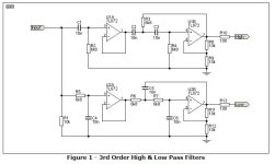
Hi, I m building a pair of speakers and I wanted to bi-amp them, so I need active crossover, Rod Eliott's project 123 "catched my eye", I can not buy the PCB's where I live so I designed it myself ( at least tried ).
Besides being a bit crowded ( wanted to make them as small as possible ) , any layout problems ?.
Please take a look.
Cheers, Bruno.
Link to article https://sound-au.com/project123.htm
Besides being a bit crowded ( wanted to make them as small as possible ) , any layout problems ?.
Please take a look.
Cheers, Bruno.
Link to article https://sound-au.com/project123.htm
Attachments
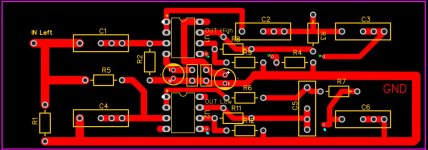
it will probably oscillate as there is no power supply or opamp decoupling
there are no output attenuators
there are no output attenuators

The grounds for your input and output cables need to be connected to the circuit and I don't see any pads for them in the PCB.
Dear Bruno,
Try to spread the ground around the unused parts of the solder side to reduce impedance. Alternatively add a ground plane on the component side of the board, as you're already paying for full copper anyway. You could also try reducing board size by moving / rotating some components. In general, reduced lengths and area give better EMI performance.
I would also recommend having similar routing for left / right channels so as to get better matching between them.
Cheers.
Last edited:
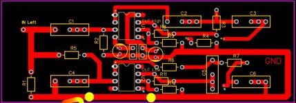
Electrically, it would work. I pay attention to loop areas, keeping the signal and its return close together to minimize circuit loops which can pickup and radiate noise.@pinholer Is it ok to solder the gnd from a coax cable here and the "center wire" to the input / output where it is on the pcb.
You might want to redo your PCB. I know it takes me several iterations to get a PCB design so that I'm happy.
@newvirus2008 " Try to spread the ground around the unused parts, if the gmd is all around the components " wouldn't that create ground loop ? Which is bad.?.
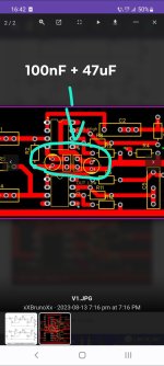
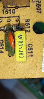
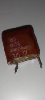
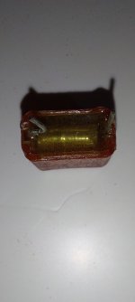
Another question, are these generic yellow caps good for this design, or these wima's. ? I also have these red ones, i took one apart for curiosity, the big red ones are rolled so are the wima's. The yellow ones look like sheets stacked.
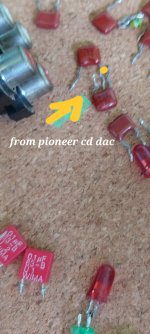
The other brownish are from a Pioneer cd player dac section.
At least for testing. Ill buy new caps , any recommendations, that won't make me broke xD.
Thank you.
The other brownish are from a Pioneer cd player dac section.
At least for testing. Ill buy new caps , any recommendations, that won't make me broke xD.
Thank you.
Attachments
Output attenuators, you mean the 100 R resistors ?
have a study of the active crossovers at Linkwitz Labs
Do you know what type they are - not such thing as a generic cap really, lots of different dielectrics, construction types, etc etc. They look like some sort of plastic film - but what? Mylar? PP?are these generic yellow caps good for this design
Polyproylene (PP) dielectric is one of the best film cap dielectrics for linearity. The nature of the dielectric and whether the construction is inductive or not are key properties. Not so much the brand. And for many audio uses the inductance may be unimportant too.
- Home
- Source & Line
- Analog Line Level
- Quick question about active crossover