Hello all,
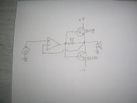
I have decided to try out this circuit described by JohnAudioTech in this video:
It is a very simple circuit, and it seemed to work quite well in his video. I built the circuit myself on a breadboard, and it didn't sound too good. I think there was some crossover distortion happening, but I haven't put it on the 'scope. It could be down to my poor breadboard layout, I'm assuming the feedback line between the output transistors and op-amp needs to be kept physically short.
What do you think of this circuit? I do appreciate John from JAT developing and sharing this class b amp circuit with us, but would it be worth building an actual desktop amplifier with this circuit? I thought it would be good to run my computer speakers, since it would be on all the time and wouldn't draw too much idle current.
I'm curious to hear what you all think!
That s exactly that, a true class B amplifier, meaning that there s no output stage current biasing, as such it will produce a lot of
crossover distorsion even if the op amp is of good perfs, you would be better building a similar amp using a pair of TDA2030 or 2040, you wouldnt even need additional transistors.
crossover distorsion even if the op amp is of good perfs, you would be better building a similar amp using a pair of TDA2030 or 2040, you wouldnt even need additional transistors.
It's a bit like the Elektuur/Elektor Edwin amplifiers from decades ago. The feedforward path via the resistor between the bases and emitters is supposed to cover the crossover region and change it from a true dead zone to one where there is still some loop gain left. Reducing the 150 ohm to some smaller value should therefore reduce crossover distortion, as long as it doesn't overload the op-amp.
You could also consider changing it into a rudimentary current dumping amplifier. QUAD's current dumping scheme is somewhat similar, but far more effective against the crossover distortion.
You could also consider changing it into a rudimentary current dumping amplifier. QUAD's current dumping scheme is somewhat similar, but far more effective against the crossover distortion.
The opamp has to cover 1.2V Vb-b dead zone by feedback. Loopgain decreases with frequency, thus high crossover distortion is inevitable. It would be good to use a small Vb-b bias voltage. As small as to keep it in class B without danger of thermal runaway, but even then helping the opamp, because dead zone would be smaller.
BTW the same circuit idea has been with us for decades, it is no new invention. It was, with one more resistor between opamp and bases, used in sixties in analog computers.
BTW the same circuit idea has been with us for decades, it is no new invention. It was, with one more resistor between opamp and bases, used in sixties in analog computers.
Last edited:
Without adding any complexity, you could try changing 150 ohm to 68 ohm and the 22 kohm feedback resistor to 8.2 kohm. You have a bit more loop gain then, especially in the crossover region. It will still be a bad amplifier, but hopefully not as bad as it is now.
This shows the problem of the crossover distortion.


When I was younger and learning much I played around with these kind of circuits for hours. Using hiher current opamps like the 4560 makes a massive difference as they can support a much higher loading (reducing the 150 ohm down to much lower levels). You can also parallel the opamp output stages to get more current (but it do correctly).
V4 and V5 in the original were just forward biased diodes.

Lets try it 🙂 Much better...Without adding any complexity, you could try changing 150 ohm to 68 ohm and the 22 kohm feedback resistor to 8.2 kohm.
When I was younger and learning much I played around with these kind of circuits for hours. Using hiher current opamps like the 4560 makes a massive difference as they can support a much higher loading (reducing the 150 ohm down to much lower levels). You can also parallel the opamp output stages to get more current (but it do correctly).
The Elektor current dumping design using a 741 always fascinated me and I have a simulation for that one.You could also consider changing it into a rudimentary current dumping amplifier.
V4 and V5 in the original were just forward biased diodes.
Attachments
Thanks everyone! You've definitely given me some ideas to consider...
Lowering the values of the op-amp output and feedback resistors looks like it will help for sure. I think using both op-amps in the LM4562 in parallel for a single channel is a must at this point. I'm not exactly sure how much current the op-amp is pushing, but 0.7V into 8ohm would demand ~60mA of current.
Lowering the values of the op-amp output and feedback resistors looks like it will help for sure. I think using both op-amps in the LM4562 in parallel for a single channel is a must at this point. I'm not exactly sure how much current the op-amp is pushing, but 0.7V into 8ohm would demand ~60mA of current.
The op-amp has to deliver about 0.7 V divided by 150 ohm (or 68 ohm) plus the base current of the output transistor, which will typically be about 20 mA in the peaks with an 8 ohm load. The base current can be a lot more if you happen to have transistors with an hFE close to the minimum spec.
You can't connect two op-amps directly in parallel. Due to their different offset voltages, among other things, their outputs would be fighting each other. What you could do, is connect the other channel as a voltage follower connected to the first channel's output, and let that drive an extra resistor to the loudspeaker.
You can't connect two op-amps directly in parallel. Due to their different offset voltages, among other things, their outputs would be fighting each other. What you could do, is connect the other channel as a voltage follower connected to the first channel's output, and let that drive an extra resistor to the loudspeaker.
Attachments
Ah, I think I'm starting to see it now.The op-amp has to deliver about 0.7 V divided by 150 ohm (or 68 ohm) plus the base current of the output transistor, which will typically be about 20 mA in the peaks with an 8 ohm load. The base current can be a lot more if you happen to have transistors with an hFE close to the minimum spec.
You can't connect two op-amps directly in parallel. Due to their different offset voltages, among other things, their outputs would be fighting each other. What you could do, is connect the other channel as a voltage follower connected to the first channel's output, and let that drive an extra resistor to the loudspeaker.
I have found this article from TI on using op-amps in parallel:
If that's the right idea, then I could try to redraw the circuit with two op-amp sections.
I'm trying to avoid biasing the output transistors, as thermal runaway could become an issue and seriously complicate the circuit.
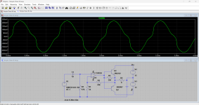
This is my way how to make a real life, working class B amplifier from the circuit suggested in post #1. Temperature is no problem, even at 100°C there is negligible idle current in the output stage. Distortion is at least acceptable, see the 10kHz wave. Please do not test at 1kHz, it does not tell much about crossover distortion. Add supply bypass capacitors like 100uF//100nF.


THD vs. power at 10kHz

10kHz stepped sine HD and scope

THD vs. power at 10kHz
10kHz stepped sine HD and scope
Attachments
Last edited:
This is my way how to make a real life, working class B amplifier from the circuit suggested in post #1. Temperature is no problem, even at 100°C there is negligible idle current in the output stage. Distortion is at least acceptable, see the 10kHz wave. Please do not test at 1kHz, it does not tell much about crossover distortion. Add supply bypass capacitors like 100uF//100nF.
View attachment 1243538
View attachment 1243539
THD vs. power at 10kHz
View attachment 1243543
10kHz stepped sine HD and scope
View attachment 1243544
Why did you remove the feedforward path (150 ohm or 68 ohm or whatever resistor)? Now you have a real dead zone.
Last edited:
I looked at these issues when I designed my HPA1 headphone amp. I used single transistor (Q6) to bias the output stage into class A (90 mA) and then as done above, put the whole thing inside the feedback loop. The OPS transitions very smoothly to class AB and the distortion at full output (32 ohms) is single digit ppm.

Last edited:
Because it does not help, it only adds more load to the opamp. It is a pseudo-improvement.Why did you remove the feedforward path (150 ohm or 68 ohm or whatever resistor)? Now you have a real dead zone.
I could understand that if your quiescent current is about 100 uA or greater, so 1/(gm,NPN + gm, PNP) < 150 ohm. The transistors then do more than the resistor, even in the middle of the crossover region.
Is that the case?
Is that the case?
With 150R "feedforward"

without 150R

One can see zero improvement with 150R, in fact distortion and swing are degraded.
Decades ago I played with this "trick", it is pointless. Small safe (to stay in class B, without runaway under any condition) added Vb-b DC is better. Bypassed by cap of course.
without 150R
One can see zero improvement with 150R, in fact distortion and swing are degraded.
Decades ago I played with this "trick", it is pointless. Small safe (to stay in class B, without runaway under any condition) added Vb-b DC is better. Bypassed by cap of course.
- Home
- Amplifiers
- Solid State
- Class B Circuit Opinions...