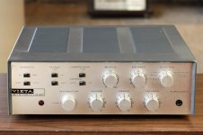
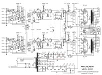
Hey there, I recently picked up a Vieta A217 integrated amp, a Spanish designed and produced model from the late 1960s. Someone already replaced the Siemens EL84s with some 6P14Ps, one of which has almost no emission. I've recapped it, replaced the bias rectifier, and it's working OK aside from the weak left channel. I have a fresh set of NOS 6P14Ps, and want to know where to set the bias on them, the schematic leaves that part out. The max line voltage I can set the amp for is 220V, and I have 230V, so about 5% high. B+ is about 10% high, at 374V on pin 8 of the rectifier. Looking at the plate curves, if my math is right, I want about -10.5V on the grid, is that right? The lowest I can adjust it down to is about -14V, and so wondering what the best approach would be. I've thought about adding a 7912 to the bias supply, which would put me in the right range.
Am I right in wanting to set the bias at -10.5V? Any reason not to put a regulator in there to drop that voltage down a bit and stabilize it?


Am I right in wanting to set the bias at -10.5V? Any reason not to put a regulator in there to drop that voltage down a bit and stabilize it?


Is the amp built on a circuit board, tag strips or point to point?
Setting a nominal voltage for the bias might not be the best approach.
Are you willing to modify the amp from its stock circuit?
Setting a nominal voltage for the bias might not be the best approach.
Are you willing to modify the amp from its stock circuit?
The phenolic pots might be the 50K bias balance shown in the schematic. To monitor the current draw of the EL84 tubes you could put 10 ohm resistors between pin 3 and ground on each tube. A 1K resistor between each screen grid and the 315 volt supply would likely make life easier on the EL84s too.
To amplify on Steve's recommendations, bias is set to a particular cathode current, rather than a grid voltage. The safest and best place to measure this is as Steve says, with a small 1% resistor in the cathode lead to ground. For your amplifier you'd crank around whatever pots you have available until you see maybe 0.30 or 0.35 VDC across each 10R cathode sensing resistor, meaning 30 or 35 milliAmps each valve. 6Pi14Pi is pretty rugged, and you may even try 40mA to see if you can hear it. If you can, you're either young or not taking enough drugs; both self-curing with time. Arf.
All good fortune,
Chris
All good fortune,
Chris
As this amp has common bias for all tubes ( only a balance for each pair) a matched quad is needed here. New EL84 fits fine.
Also adding 10 ohm resistors in the cathode circuit will make adjustment better. 30-35mA as suggested would be a target.
Redesigning to individual bias adjustment is a waste of time as matched quads are easily obtainable and will consist of
equal tubes with matching S and Ia
Also adding 10 ohm resistors in the cathode circuit will make adjustment better. 30-35mA as suggested would be a target.
Redesigning to individual bias adjustment is a waste of time as matched quads are easily obtainable and will consist of
equal tubes with matching S and Ia
Hey thanks everyone. I'll add some resistors to the cathode circuit and see what I come up with. The new tubes I have are a matched quad.
I think that is too hot. I have not seen plate curves with G2 at 315V, the datasheet I got only shows plate curves for G2 at 250V. Based on simulations, for 350V B+ you will need -12.5 for 35mA. I would start at -14 and then reduce until you reach the suggested values in #5 & #6.Looking at the plate curves, if my math is right, I want about -10.5V on the grid, is that right?
no need to fit cathode resistirs to determine tube current,
just measure DC resistance of each half primary winding (amp off and cold)
then measure voltages across half primaries (amp on and hot)
and now use ohms law I=V/R to calculate individual plate currents;
you may also note the DCR numbers on a sticker to stay with the amp just in case ...
just measure DC resistance of each half primary winding (amp off and cold)
then measure voltages across half primaries (amp on and hot)
and now use ohms law I=V/R to calculate individual plate currents;
you may also note the DCR numbers on a sticker to stay with the amp just in case ...
Your amp is over 60 years old!!!! Well done you for keeping it alive 😍
As you've replaced power output stage valves with a new set .....are V4 and V5 performing as designed?
Do they mirror each other? A test point comparison chart would answer this.
Check your resistors ....do they match? They may have drifted out by now.
As you've replaced power output stage valves with a new set .....are V4 and V5 performing as designed?
Do they mirror each other? A test point comparison chart would answer this.
Check your resistors ....do they match? They may have drifted out by now.
There is a safety issue involved that we shouldn't ignore. Folk making inquires on the InterWebs come from an unknowable experience base. Some may be hobbyists just getting our feet wet, and others may be JohnNeutron, knowing more than anybody about some deeply related things, but interested in some new thing.no need to fit cathode resistirs to determine tube current,
just measure DC resistance of each half primary winding (amp off and cold)
then measure voltages across half primaries (amp on and hot)
and now use ohms law I=V/R to calculate individual plate currents;
you may also note the DCR numbers on a sticker to stay with the amp just in case ...
Safest is to assume (parse for: makes an *** of U and ME) that a random reader is interested but not yet totally knowledgeable (as we all are). Cathode resistors give us an unambiguous, safe, temperature insensitive, 1% plus meter accurate, should-have-been-there-already measurement. So, I campaign for this as a standard practice for professional restorations, possibly even including chassis mount test points at the cathodes.
Was looking at an acquaintance's H. H. Scott early 299 today. Somebody in its earlier history had already installed 10R cathode resistors, test points sockets, some effort to remove the speaker polarity switching, nice JJ B+ caps, some modern but Russian coupling caps where needed, etc., beautiful work. I really couldn't have done better. Sadly, I'm pretty certain that the power transformer has some shorted internal windings. When I quit crying tomorrow, I'll cut all the other secondaries fully free to be fersure fersure, and there it is.
All good fortune, and cry me a river,
Chris
Nothing much to add that hasn't already been said apart from setting the bias @ X volts or the cathode current @ YmA doesn't give one the full picture of a valves DC operating conditions. A better methodology might be to determine the valves quiescent power OP. EG Va * Ik. I set my amps OP valves at about 75% of datasheet maximum as I'm after long life as apposed to maximum OP power.
Andy.
Andy.
Yeah, I'm no stranger to vintage equipment! I've wanted a Scott amp for a long time but in Europe they are so, so expensive, and need autoformers, etc. I came across this Vieta model and really like the design. It's also built like a tank with very large transformers, etc. They are plentiful in Spain and go for around 200€ so provided it sounds like it should it will be great bang for the buck.Your amp is over 60 years old!!!! Well done you for keeping it alive 😍
As you've replaced power output stage valves with a new set .....are V4 and V5 performing as designed?
Do they mirror each other? A test point comparison chart would answer this.
Check your resistors ....do they match? They may have drifted out by now.
Aside from output all the tubes are original Siemens, both halves of V4 and V5 test very strong. The phase inverters are working correctly and have identical signals on their outputs, plenty of gain from the driver and both channels look the same on a scope. I spot-checked the resistors and haven't found any that are more than a couple % off. The coupling caps were also spot-checked for capacitance and leakage and seem to be fine. This is surprising since I'm used to American gear full of leaky bumblebees etc., and this amp has"mustard" caps that seem to be either dead reliable or absolute garbage depending on who you ask.
" both channels look the same on a scope"
"Yeah, I'm no stranger to vintage equipment"
You have great resources to fix your amp and experience too,please continue!
Going over all solder joints using a jewellers monocle may restore dry joins.
Looking at the schematic the signal path is quite long.....several pots and switches etc before the output.
Maybe isolate each stage and examine it under your scope as you go along.
🙂
Following Sorento's suggested method, all four new tubes are running between 31.5 and 32ma so I'm gonna leave it as-is.
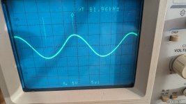
I've got two more problems to solve now: the phono stage is oscillating like crazy, I've got an 11V peak-to-peak sinewave at 82kHz on the second plates of both V1 and V2. Odd that it's both channels, yeah? I've also got a fairly loud hum in both channels, all inputs, like a ground loop. If I touch the chassis with my hand the level drops quite a bit. This is using the old 2-prong non-grounded plug, and it's going through an isolation transformer. I'm guessing the first step is to replace that power cord with a proper grounded one and see how it goes from there.
I've got two more problems to solve now: the phono stage is oscillating like crazy, I've got an 11V peak-to-peak sinewave at 82kHz on the second plates of both V1 and V2. Odd that it's both channels, yeah? I've also got a fairly loud hum in both channels, all inputs, like a ground loop. If I touch the chassis with my hand the level drops quite a bit. This is using the old 2-prong non-grounded plug, and it's going through an isolation transformer. I'm guessing the first step is to replace that power cord with a proper grounded one and see how it goes from there.

Someone already replaced the Siemens EL84s with some 6P14Ps, one of which has almost no emission.
Try with the amp closed (with its cover and lower plate screwed on)Following Sorento's suggested method, all four new tubes are running between 31.5 and 32ma so I'm gonna leave it as-is.
I've got two more problems to solve now: the phono stage is oscillating like crazy, I've got an 11V peak-to-peak sinewave at 82kHz on the second plates of both V1 and V2. Odd that it's both channels, yeah? I've also got a fairly loud hum in both channels, all inputs, like a ground loop. If I touch the chassis with my hand the level drops quite a bit. This is using the old 2-prong non-grounded plug, and it's going through an isolation transformer. I'm guessing the first step is to replace that power cord with a proper grounded one and see how it goes from there.View attachment 1243933
- Home
- Amplifiers
- Tubes / Valves
- Little help calculating bias for an EL84 amp - Vieta A217
