Hello,
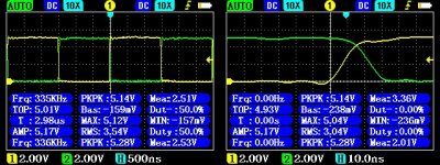
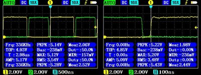
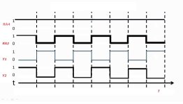
lately, experimenting with audio stuff, I kind of moved away from that and focused on power supply stuff, after some experiments with diferent topologies I found that PushPull topology in my opinion is the most suitable for my needs, at least in my experience using them in combination with Jung Didden super regulators, it work very good in combination with push pull. I'm started getting some ideas and just want to try to make an simple digital push pull using pic12f1840. What I have figured out is our small pic on my surprise is capable to deliver pwm frequency of 333kHz. I have tried pic's internal half bridge pwm configuration but it seems our pic is not able to produce complementary outputs 50:50 while duty is not excatly at 50%, instead when one of the complementary outputs is moved from 50% duty for examle when I set HI to duty 40% LO is automaticaly moved to 60% duty, or vicewersa, that way its not capable for push pull topology which reguire exact 50:50 duty. Than I got idea to use single out pwm but this time one SN74LVC2G86 gate so when HI=high LO is automaticaly =lo and vicewersa, that way I am able to produce fully proportional HI/LO needed for push pull topology and the same time I would be able to have changeable duty cicle from zero to 100%, the same way changeable push pull Vout. Later I got idea about feedback. Feedback is based on voltage to frequency converter ad7740. Based on resistor divider on push pull output I have added one opamp which will amplify watching signal at resistor divider and amplify it to full resolution 0-2.5V, that way ad7740 will give me at their output frequency range from zero to 32768Hz at full resolution. Ad7740 output is than isolated by an signal isolator. On pic side I would need to count pulses and change pwm duty on the fly, that mean my push pull have their fb. What is your opinion, might this work good? As you can see from picture pic12f1840 produce nice pwm even on 333kHz frequency.
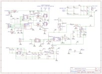
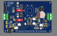
Here is some pictures about pic's pwm I measured by osciloscope, one picture is without dead time and seccond is with dead time. Third picture is my idea about pic based push pull dc-dc converter just for test purpose. I know that much better mcu can be used here but I just want to see what can be done using our small 8bit mcu! Let me know your opinion!
Attachments
Last edited:
Here is simulation result abot resistor divider voltage amplification trought opamp to give me 0 to 2.5V needed for ad7740 to give me full resolution from zero to 32768Hz freq resolution which I will count on pic to determine voltage at resistor divider. My idea as a frequency based isolated feedback for our push pull. As you can see opamp sense 100mV at resistor divider or 1V at push pull Vout and amplify that for ad7740 full resolution which is trought ad7740 and isolator sent back to pic which will count frequency and regulate pwm. Pic at 100kHz fixed pwm frequency as which I want to setup will have only +-40 available pwm duty steps to regulate push pull.
Attachments
Last edited:
