Hi Everyone,
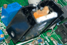
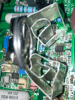
I recently rebuilt an amp with heatsinks similar to the OEM. The heatsink is rated at 20C/W. These were the only heatsinks I could find that fit the PCB footprint. Unfortunately I forgot to align screw holes and I've used a pencil to press the heatsink against the transistor. I used a thermal laser gun to measure the heatsink temperature around 70-80C. Is 70-80C too hot? Is there a target temperature? The IRF9610 datasheet doesn't specify much. I'm thinking about adding aluminum from an aluminum can. Thanks for the help.
I recently rebuilt an amp with heatsinks similar to the OEM. The heatsink is rated at 20C/W. These were the only heatsinks I could find that fit the PCB footprint. Unfortunately I forgot to align screw holes and I've used a pencil to press the heatsink against the transistor. I used a thermal laser gun to measure the heatsink temperature around 70-80C. Is 70-80C too hot? Is there a target temperature? The IRF9610 datasheet doesn't specify much. I'm thinking about adding aluminum from an aluminum can. Thanks for the help.
Attachments
It's probably OK, but too hot for me. I don't like to exceed about 60C and will add surface area or use a different heat sink. Be careful trusting IR readings unless you know the emissivity of the target (flat black paint is your friend) and that the target is occupying most of the measurement area. For little stuff there's a great little IR tool from Thermoworks, or check your readings with a thermocouple.
https://www.thermoworks.com/close-focus-ir/
https://www.thermoworks.com/close-focus-ir/
It depends on the device. A device has a certain temp difference between the junction and the case. If the heatsink (is case) temp is 70C, the junction will be higher.
How much higher? There is a spec in the datasheet called thermal resistance junction to case. Multiply that with the power dissipation to get the junction temp above the heatsink.
Junction temp should conservatively be limited to 120C or so.
So to answer your question, you need to know 1) the thermal R between junction and case (this is in the datasheet) and 2) the power dissipation of the device in W.
Jan
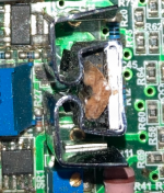
I found that the laser thermometer was hit and miss especially with smaller SMD components in the background. I remember pointing the laser on the flat black sections of the heatsink and those readings ranged from 70-80C. Thanks for your response. I might consider the IR tool you recommended if I attempt to rebuild another one of these amps (Creek Audio Destiny - IMO the design is too dense with inadequate thermal management). In an attempt to shave off a few more degrees I managed to add a DIY folded aluminum heatsink from a soda can and used a keyring for better heat transfer. The aluminum doesn't get as hot as the manufactured heatsink but at least I've improved the overall heatsink, it seems.It's probably OK, but too hot for me. I don't like to exceed about 60C and will add surface area or use a different heat sink. Be careful trusting IR readings unless you know the emissivity of the target (flat black paint is your friend) and that the target is occupying most of the measurement area. For little stuff there's a great little IR tool from Thermoworks, or check your readings with a thermocouple.
https://www.thermoworks.com/close-focus-ir/
Attachments
Yes, not bolted I used a wood from a pencil to compress the heatsink against the MOSFET.Are you saying the device is not bolted to the heat sink?
It depends on the device. A device has a certain temp difference between the junction and the case. If the heatsink (is case) temp is 70C, the junction will be higher.
How much higher? There is a spec in the datasheet called thermal resistance junction to case. Multiply that with the power dissipation to get the junction temp above the heatsink.
Junction temp should conservatively be limited to 120C or so.
So to answer your question, you need to know 1) the thermal R between junction and case (this is in the datasheet) and 2) the power dissipation of the device in W.
Jan
I went to the workshopThe operating junction temperature cannot exceed 150° C so halve that value and we get 75° C. On the borderline but designed to fail. (Gives us things to do in the workshop).
I would be happier with a larger heatsink.
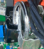
") Thanks for the response. I added a DIY heatsink to the backside, and a keyring for better compression. I believe this will improve the heat sinking. The amp is a PITA to dissemble.
Thanks for the response. I added a DIY heatsink to the backside, and a keyring for better compression. I believe this will improve the heat sinking. The amp is a PITA to dissemble.Attachments

I see. I'm unable to measure the junction temperature and have been using the heatsink temperature as reference for how well the heat is dissipating. I realize this can easily be misleading if the heatsink isn't firmly attached the MOSFET. Hopefully I've added a few more years with my upgraded setup (BTW this amp is a PITA to dissemble to remove the current heatsinks). Thanks for your response.It depends on the device. A device has a certain temp difference between the junction and the case. If the heatsink (is case) temp is 70C, the junction will be higher.
How much higher? There is a spec in the datasheet called thermal resistance junction to case. Multiply that with the power dissipation to get the junction temp above the heatsink.
Junction temp should conservatively be limited to 120C or so.
So to answer your question, you need to know 1) the thermal R between junction and case (this is in the datasheet) and 2) the power dissipation of the device in W.
Jan
Attachments


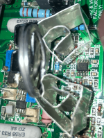
Thanks! I did add a DIY heatsink to the back with a keyring for better heat transfer. Unfortunately I've since returned the IR temp gun but can touch the heatsink for around 5 seconds which puts temperature in the ball park of 60-70. So it seems adding the DIY heatsink has improved things.The operating junction temperature cannot exceed 150° C so halve that value and we get 75° C. On the borderline but designed to fail. (Gives us things to do in the workshop).
I would be happier with a larger heatsink.
Nor can we. As explained, you need two data points. 1) how much does the device dissipate? Do you know that, how much volts across it, how much current through it?I see. I'm unable to measure the junction temperature
2) the device thermal resistance from junction to case. You can look that up in the data sheet.
When you have those data points, you can simply calculate the temp difference between junction and case (=heatsink, plus a couple degrees). As you also know the heatsink temp, that gives you the junction temp.
Jan
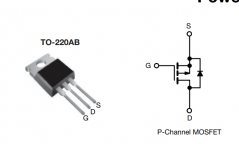
How do I measure the voltage and current through the device? The device is IRF9610, also here's the schematic of the amp. I have a multimeter and know how to identify the Gate Drain and Source.What device is this? Do you know the voltage across it and current through it?
I can do the sums for you.
Everything else is pie in the sky.
Jan
Thanks, Gregory
Attachments
Last edited:
I can touch the heatsinks for about 5 seconds before recoil. No screamsToo hot.
A quick test: choose a finger you don't care much about, and touch the heatsink: if you scream, it's too hot.
Junction temperature is one thing, accelerated aging of the components nearby is another, possibly even the solder.
No fan, the heatsink are under a vented lid.I'd worry about what changes when you put it in the enclosure. Is there a fan? Can you put in a small fan to get some air in the enclosure?
You'd measure the voltage between S and D, see attachment.How do I measure the voltage and current through the device? The device is IRF9610, also here's the schematic of the amp. I have a multimeter and know how to identify the Gate Drain and Source.
Thanks, Gregory
The current can be measured indirectly. Measure the voltage across R26, we can calculate current from the resistor value (Ohm's Law and all that).
BTW I wonder whether Q14 is really an IRF9610, or an IRF610 ...
Jan
Attachments
Thanks for the guidance. I'll have to see if I can find a safe method to measure those voltage. I've shorted too many components in the past. Between the variable resistor and heatsink there's barely enough clearance for probes to access the S and D, and R26. R50 is also too close to the heatsink and variable resistor.You'd measure the voltage between S and D, see attachment.
The current can be measured indirectly. Measure the voltage across R26, we can calculate current from the resistor value (Ohm's Law and all that).
BTW I wonder whether Q14 is really an IRF9610, or an IRF610 ...
Jan
Why do you wonder if its either the IR610 or IRF9610? I purchased the IRF9610s from mouser.com.
Last edited:
- Home
- Amplifiers
- Solid State
- IRF9610 Heatsink Measures 70-80 Celsius: Is this too hot?