I realised that the 9610 is a P-channel device so the drain should be negative with respect to the source.
With a pos supply I'd expect an N-channel device.
But I think it's correctly connected in this schematic, just unusual (to me)
To the measurement: try to connect up the probes while it is off, then switch it on.
Avoids those jittery disasters ;-)
Jan
With a pos supply I'd expect an N-channel device.
But I think it's correctly connected in this schematic, just unusual (to me)
To the measurement: try to connect up the probes while it is off, then switch it on.
Avoids those jittery disasters ;-)
Jan
If it blows up, it's too hot.
FWIW, I've run IXTH6N50D2 with a 100°C heatsink in a class A amp for hours at a time... They don't care.
I've also run an IRF740 so hot it fell out of the board it was mounted to (solder melted, gravity pulled it out... not my design, added a heatsink) but the MOSFET still worked when I reinstalled it.
Last edited:
Ok good to know! Thanks thats crazy the IRF740 fell out of the board. I think I've improved the heatsinking with the added diy heatsink out of aluminum. Thanks. Good to know these MOSFETs are rugged.If it blows up, it's too hot.
FWIW, I've run IXTH6N50D2 with a 100°C heatsink in a class A amp for hours at a time... They don't care.
I've also run an IRF740 so hot it fell out of the board it was mounted to (solder melted, gravity pulled it out... not my design, added a heatsink) but the MOSFET still worked when I reinstalled it.
Thanks for everyones help and input. The amp had been working for a year with the manufactured heatsinks before I checked the temperatures. This is a good indicator, and now with the added diy heatsinks made out of aluminum (which are also getting hot) I feel more confident the IRF9610s are not running too hot.
True 😉 Just like the Operation game lol. But those resistors are surface mount and too small for the alligator or grabber probes. The Drain is easy to probe, but now I can't fit the grabber under the heatsinks to probe the Source. Crunchy design. I'm going to call it good for now. Thanks. GregoryI realised that the 9610 is a P-channel device so the drain should be negative with respect to the source.
With a pos supply I'd expect an N-channel device.
But I think it's correctly connected in this schematic, just unusual (to me)
To the measurement: try to connect up the probes while it is off, then switch it on.
Avoids those jittery disasters ;-)
Jan
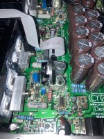
PS FWIW the Creek Audio 5350SE has a very similar amp section and those IRF9610 heatsinks seem to have more surface area... Sorry I couldn't find a higher resolution photo.
Attachments
Last edited:
I Have measured Q14 drain to Q12 drain: 56 volts. If that helps.I realised that the 9610 is a P-channel device so the drain should be negative with respect to the source.
With a pos supply I'd expect an N-channel device.
But I think it's correctly connected in this schematic, just unusual (to me)
To the measurement: try to connect up the probes while it is off, then switch it on.
Avoids those jittery disasters ;-)
Jan
Very good. Now what is the voltage across R26? We need that to calculate the current through the FET.
Jan
Jan
Looking at the data sheet, you see the attached. The thermal resistance between junction and case is 3.5C/W. So for every watt the FET dissipates, the junction is 3.5C hotter than the case. Then there's a small thermal resistance between the case and the heatsink, here estimated at 0.5C/W. Total 4C/W.
Let us estimate the current through the FET at 50mA, I don't know how close that is but just for the discussion. With 56V across it, that's a dissipation of 0.05 x 56 = 2.8W. That means that the junction will be 2.8 x 4 = 11.2C hotter than the heatsink. With a heatsink of 70C, that makes the junction about 81.2C which is totally safe for the FET.

Measuring the voltage across R26 will allow accurate calculation of the FET current.
Jan
Let us estimate the current through the FET at 50mA, I don't know how close that is but just for the discussion. With 56V across it, that's a dissipation of 0.05 x 56 = 2.8W. That means that the junction will be 2.8 x 4 = 11.2C hotter than the heatsink. With a heatsink of 70C, that makes the junction about 81.2C which is totally safe for the FET.
Measuring the voltage across R26 will allow accurate calculation of the FET current.
Jan
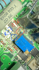
Thanks for the explanation and showing the math. It’s reassuring that the MOSFET junction temperature is in the safe zone. I’ve attached a zoomed in photo of R26. This is what I up against. I can’t risk shorting R26 with R27. I managed to briefly measure .02V across R26. R26 is 62 Ohms. .02V/62 Ohms That yields 0.3 milliamps?! Does not sound right. Again I wasn’t able to firmly connect the probes to ends of R26 which is 3 mm in length for scale. It’s dicy.Looking at the data sheet, you see the attached. The thermal resistance between junction and case is 3.5C/W. So for every watt the FET dissipates, the junction is 3.5C hotter than the case. Then there's a small thermal resistance between the case and the heatsink, here estimated at 0.5C/W. Total 4C/W.
Let us estimate the current through the FET at 50mA, I don't know how close that is but just for the discussion. With 56V across it, that's a dissipation of 0.05 x 56 = 2.8W. That means that the junction will be 2.8 x 4 = 11.2C hotter than the heatsink. With a heatsink of 70C, that makes the junction about 81.2C which is totally safe for the FET.
View attachment 1051587
Measuring the voltage across R26 will allow accurate calculation of the FET current.
Jan
Attachments
Last edited:
Then it's OK.I can touch the heatsinks for about 5 seconds before recoil. No screams 🙂
Still, a better solution is to find a way to attach the MOSFet to the big heatsink nearby. Of course, it's a lot more work: electrically insulate the device, and add a gate stopper resistor to be soldered directly to the pin.

Yeah measuring that is a b*tch. I have one of those ' tweezer multimeters' but even with that it's dicy. I think you can stop worriyng. Even with a FET current of a few 100mA it is safe, and it would surely be less than that.Thanks for the explanation and showing the math. It’s reassuring that the MOSFET junction temperature is in the safe zone. I’ve attached a zoomed in photo of R26. This is what I up against. I can’t risk shorting R26 with R27. I managed to briefly measure .02V across R26. R26 is 62 Ohms. .02V/62 Ohms That yields 0.3 milliamps?! Does not sound right. Again I wasn’t able to firmly connect the probes to ends of R26 which is 3 mm in length for scale. It’s dicy.
Was nice to work with you on this.
Jan
As the thermal resistance of the original heatsink is known, there is another way to do the calculation for the original heatsink, without measuring any currents:
Heatsink temperature: 80 degrees Celsius (opening post)
Ambient temperature: 20 degrees Celsius (guess)
Thermal resistance heatsink-ambient: 20 K/W (opening post)
Thermal resistance junction-heatsink: 6.4 K/W + 0.5 K/W = 6.9 K/W (datasheet https://nl.mouser.com/datasheet/2/427/91080-1768447.pdf , inconsistent with Jan's post #29)
Maximum allowable junction temperature: 150 degrees C (datasheet)
Temperature drop heatsink-ambient: 80 degrees Celsius - 20 degrees Celsius = 60 K
Temperature drop junction-ambient: proportional to the thermal resistance, so (20 K/W + 6.9 K/W)/(20 K/W) times 60 K = 80.7 K
(You can also explicitly calculate the power dissipation of about 60 K/(20 K/W) = 3 W and take it from there.)
The junction then stays below 150 degrees Celsius up to 69.3 degrees Celsius ambient temperature. At 20 degrees Celsius ambient temperature, it will be around 100.7 degrees Celsius.
There was no urgent need to improve cooling, but it improves reliability and lifetime, so it wasn't a waste of time either. 😉
Last edited:
I highly doubt it's 20°C inside that chassis. Try ambient = 40°C at least...
In the case where my MOSFET fell out of the board, the ambient temperature (inside the chassis) was ~60°C...
In the case where my MOSFET fell out of the board, the ambient temperature (inside the chassis) was ~60°C...
If that 80 degrees Celsius measured heatsink temperature was at 40 degrees Celsius ambient temperature, then the power dissipation was only 2 W instead of 3 W, and the junction temperature was only 13.8 K above the heatsink, so 93.8 degrees Celsius instead of 100.7 degrees Celsius.
Likewise. Thanks again for the help. I can rest assured that these are not running too hot. So much grey is separated to black and white when you introduce math and physics!Yeah measuring that is a b*tch. I have one of those ' tweezer multimeters' but even with that it's dicy. I think you can stop worriyng. Even with a FET current of a few 100mA it is safe, and it would surely be less than that.
Was nice to work with you on this.
Jan
Thanks for the calculations. I am noticing the original heatsinks are a bit cooler now with the added diy heatsinks. That should put the heatsink temperature closer to roughly 70C based human touch temperature sensitivity. Ambient in enclosed amp circuit seems more like 30C, so the MOSFET junction is around 97.25 C 🙂. I'll definitely keep this amp out of any enclosed spaces.As the thermal resistance of the original heatsink is known, there is another way to do the calculation for the original heatsink, without measuring any currents:
Heatsink temperature: 80 degrees Celsius (opening post)
Ambient temperature: 20 degrees Celsius (guess)
Thermal resistance heatsink-ambient: 20 K/W (opening post)
Thermal resistance junction-heatsink: 6.4 K/W + 0.5 K/W = 6.9 K/W (datasheet https://nl.mouser.com/datasheet/2/427/91080-1768447.pdf , inconsistent with Jan's post #29)
Maximum allowable junction temperature: 150 degrees C (datasheet)
Temperature drop heatsink-ambient: 80 degrees Celsius - 20 degrees Celsius = 60 K
Temperature drop junction-ambient: proportional to the thermal resistance, so (20 K/W + 6.9 K/W)/(20 K/W) times 60 K = 80.7 K
(You can also explicitly calculate the power dissipation of about 60 K/(20 K/W) = 3 W and take it from there.)
The junction then stays below 150 degrees Celsius up to 69.3 degrees Celsius ambient temperature. At 20 degrees Celsius ambient temperature, it will be around 100.7 degrees Celsius.
There was no urgent need to improve cooling, but it improves reliability and lifetime, so it wasn't a waste of time either. 😉
Last edited:
Hi Jan,Yeah measuring that is a b*tch. I have one of those ' tweezer multimeters' but even with that it's dicy. I think you can stop worriyng. Even with a FET current of a few 100mA it is safe, and it would surely be less than that.
Was nice to work with you on this.
Jan
I was able to measure the voltage across R26 (62 Ohms)! By looking closer at the schematic I found an easier spot to place one of the probes (the base of q13). Anyway, it’s 1 Volt across R26 and R126, so that’s 1/62 Amps. Given Vds=48 volts and voltage across R26, can you show me how to calculate the power for IRF9610?
1/62 * 48 = 0.77W
With total thermal resistance juncion to heatsink 4-5 K/W, the junction appears to be only 5 degree hotter.
Are you sure R26 is 62ohm?
With total thermal resistance juncion to heatsink 4-5 K/W, the junction appears to be only 5 degree hotter.
Are you sure R26 is 62ohm?
1/62 * 48 = 0.77W
With total thermal resistance juncion to heatsink 4-5 K/W, the junction appears to be only 5 degree hotter.
Are you sure R26 is 62ohm?
Thanks. Yes, I measured 62 Ohms on R26 and R126. I also calculated the same wattage which seems too low considering the amount of heat. The schematic shows a transistor (Q19) in between R26 and the source of Q14(IRF9610). How do you know the source current ‘Is’ is equal to the current going through R26? It seems there’s something missing in the equation given the amount of heat. The heat sinks for Q14 are around 70c after reaching thermal equilibrium on idle, which takes a good hour. The ambient temperature is probably no more than 40c. I base that figure on readings and the heat sink temperature for the output devices, also round 40c.
Last edited:
- Home
- Amplifiers
- Solid State
- IRF9610 Heatsink Measures 70-80 Celsius: Is this too hot?