Yes the phono board was sold separately. The analog power supply has the same +/- 15 volts with LM317/337.1. The subject of the post was adding a second toroid on top of it upside down. You could reread all the info again in the other thread.
2. Your phono board has a very healthy +/-15V by LM317/337 that don't mind 50 mA extra. It is very odd that they did not use that +/-15V but I guess that the device was not sold standard with the phono boards which would explain it.
3. The 2 x 7V toroid could be replaced for 2 x15V one but it would require more serious surgery and possible challenges. I leave it to you to examine that possibility. I think it is too difficult.
Both ideas 1 and 2 have slight drawbacks but a few minutes are enough to find out what is most easy to implement.
Attachments
Repeating myself makes me feel old but 25V instead of 50V and the LM317/337 having lower idle current than Zener diodes makes the difference. As the internal oven now is set to luke warm/room temperature semis, caps and whatnot won't heat up of too high ambient temp.
Anyway, you have enough ideas to solve the heat issue for a very large part. You simply could use wires for testing it and then measure temperatures...
Anyway, you have enough ideas to solve the heat issue for a very large part. You simply could use wires for testing it and then measure temperatures...
Last edited:
The schematics are confusing as they use different names for the same PSU connections. Another possibility is to keep the Zener diodes but feed them straight from +LV2 and -LV2 (if these are the 25V points as I get confused by the schematics!). Recalculate the power resistors.
Again 25V difference. Again less heat.
Again 25V difference. Again less heat.
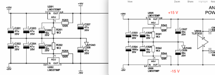
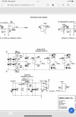
What I ask myself is if the +/-25V are one and the same. Probably are but I want to be sure. That "analog PSU" is completely lacking in the copy of the service manual you posted!!! So it is not strange that I am running in circles. Please remember that I don't have the device standing in front of me. Found the complete manual in the other thread (sigh) and that "analog PSU" only has 2 x OPA2134 and 1 x TL72 as load so take your chances.
If we are right and it seems we are, then it is incredibly stupid that Creek connected the 4 x 15V Zener diodes to +/- 50V 😀 I hope you'll see that brands do make mistakes.
So that is enough (no, too much) time spent. Good luck with the Creek and the modifications.
If we are right and it seems we are, then it is incredibly stupid that Creek connected the 4 x 15V Zener diodes to +/- 50V 😀 I hope you'll see that brands do make mistakes.
So that is enough (no, too much) time spent. Good luck with the Creek and the modifications.
Last edited:
Hmm, the zener diodes are connected to 15 volts, after the power resistors drop down the voltage from 50 to 15 volts.What I ask myself is if the +/-25V are one and the same. Probably are but I want to be sure. That "analog PSU" is completely lacking in the copy of the service manual you posted!!! So it is not strange that I am running in circles. Please remember that I don't have the device standing in front of me. Found the complete manual in the other thread (sigh) and that "analog PSU" only has 2 x OPA2134 and 1 x TL72 as load so take your chances.
If we are right and it seems we are, then it is incredibly stupid that Creek connected the 4 x 15V Zener diodes to +/- 50V 😀 I hope you'll see that brands do make mistakes.
So that is enough (no, too much) time spent. Good luck with the Creek and the modifications.
I think you rushed to conclusions with inadequate information. It’s not a fire drill, no pun intended, hopefully 🤞ha. For example, the phono preamp 15VDC you recommended is powering 4 x OPA2134UAs and 2 x SSM2019BRNs.
I’m going to stick with what I have. DC offset and idle voltage values are stable and the case is not hotter than 40C. 70C for thr IRF9610 heatsinks and 50C ambient is a bit warm, IMO. Still well below max values. Those power resistors are rated up to 250C. But time will tell and granted I’m new at this. I’ll be happy if it lasts 10 years. I am losing my hearing anyway lol.
Thanks for the advice and feedback.
Last edited:
Your reaction says a lot. I did not rush into conclusions as both PSUs are able to supply the extra few opamps. I had to do things blind/from paper and almost have to beg for answers (that are not given, see the 25V question) with incomplete schematics from someone that thinks sticking bandaids is better than preventing to cut oneself. The calculations say what is wrong, the modifications are given for 80...90% and only the last details have to be done by you to solve matters the most optimal way.
The Zener diodes are NOT connected to 15V, they create the 15V with the resistors dropping 35V as described more than once. I spoke of the "analog PSU" but the Phono PSU will also be able to supply the few extra opamps besides the 50 mA the 4 x OPA2134UAs and 2 x SSM2019BRN consume. The LM317 and 1000 µF give it away that 50 mA extra won't cause disturbance.
Stick to thick and be happy.
Last edited:
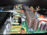
After more poking around I found another few hot spots. The temperature of Q12/112 a SMD MOSFET is 80C! , and very close to Q14/Q114, and a few other THT resistors at board leavel measuring 100C +. I think it’s safe to conclude again that the main amp section is over crowded with components with inadequate thermal management. Seems like a whack-a-mole scenario and I need to learn more about its design and circuits in general before using an alternative psu for the dc servo and current sensor. Can anyone refer me to a solid intro book to electrical circuits that might provide insight into the techniques used in the design of this amp? For now I’m going to use a pair of quiet $15 fans. I really love the sound of the Destiny. Thanks again for the insight and advice @jean-paul. Yes stick with the thick and be happy.
Mac Mini 2012 (Audirvana, Spotify, TuneIn Radio via Kodi)
Denafrips Ares II
Technics SL-1301
Creek Audio Destiny
Wharfedale Diamond 10.7.
Mac Mini 2012 (Audirvana, Spotify, TuneIn Radio via Kodi)
Denafrips Ares II
Technics SL-1301
Creek Audio Destiny
Wharfedale Diamond 10.7.
Last edited:
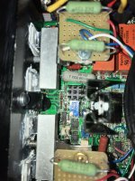
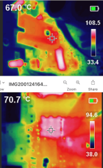
Update: Properly installed new (taller) heatsinks for Q14/Q114. Thermal camera measures hottest spot on heatsinks at 67C 🙂
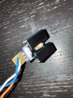
Added a surface mount heatsink to Q12/Q112. Thermal camera measures heatsinks at 71C 🙂. I tried to move Q12/112 above board using a TO-252 breakout board w/ heatsink but ran out of space after constructing a device that was electrically insulated and could mount to the main heatsinks. Overall, these changes have improved thermal management and should add more life to the PCB and close by components (also replaced) that were swamped in the excess heat.
Added a surface mount heatsink to Q12/Q112. Thermal camera measures heatsinks at 71C 🙂. I tried to move Q12/112 above board using a TO-252 breakout board w/ heatsink but ran out of space after constructing a device that was electrically insulated and could mount to the main heatsinks. Overall, these changes have improved thermal management and should add more life to the PCB and close by components (also replaced) that were swamped in the excess heat.
Attachments

60C (140F) is the standard maximum temperature in regulations - hotter than that a guard screen should be fitted, and even below that a warning sticker is a good idea - "caution hot surface". 60C can be touched for a few seconds without a burn, giving time to retract your hand. A guard screen can help ensure adequate space around the heatsink for ventilation too (like the wall stand-offs on the back of fridges).
Thanks for your response. This area is not user accessible and photos show what’s under the lid. I am not sure if adding a guard screen would help in an already cramped area. The the temperature of the lid itself maxed out around 45C.
Update: Successfully moved Q12/112 above the main amp board with a DPAK adapter board found on OSHPARK.com and heatsink. Header pins were bent into "feet" and soldered to the original SMD pads. Heatsink temperature is ~65C. There are no more hotspots (80C+) on the amp main board PCBs. Board temperatures are around 50-60C.
https://www.diyaudio.com/community/...sistor-above-board.402878/page-2#post-7529546
https://www.diyaudio.com/community/...sistor-above-board.402878/page-2#post-7529546
Attachments
On itself, the heatsink temp is not the driving factor.
The important thing is the temperature of the die junction inside the device.
It is easy to calculate that:
Calculate the dissipation (basically Vce (or Vds for a FET) times Ic (or Id for a FET)), which gives you dissipation in Watts.
Then look in the data sheet to find the thermal resistance from junction to case, which will be something like Tjc, in degrees per Watt.
Multiply dissipation in Watt by Tjc in degr/Watt to get the temp difference between junction and case.
Add that to the heatsink temp to find the junction temp, which of course should be below the max Tj in the data sheet.
Lets take an example. Id = 0.5A, Vds = 35V (substitute Ic and Vce for a bipolar transistor), giving a dissipation of 17.5W
In the data sheet, Tjc is specified as, say, 1.5 degree/W. That means that the internal junction temp will be 17.5 * 1.5 = 26.25 degrees above the case temp which is basically the heatsink temp. Thus junction temp Tj is 60 deg (heatsink) + 26.25 deg = 86.25 degr.
That's totally safe; most power devices have a max Tj of 125 deg*.
Jan
*Degr in degrees Celcius

Thanks for showing how to calculate the die junction temperature. Not to gloss over the die junction temperature, I just didn't want to have redundant posts and summarized those die temperature calculations in the linked post which focused more on Q12/112. The other major motivation was to cool down the amp main board. AFAIK 90C is too hot for a PCB. And there were several 80C+ hot spots from surface mount components (resistors and MOSFETs). Q12/Q112 were the last to be elevated above board.
- Home
- Amplifiers
- Solid State
- IRF9610 Heatsink Measures 70-80 Celsius: Is this too hot?