PCIe Dream

I am in search of a PCIe soundcard with coax/RCA (or BNC) S/PDIF (75ohm?) output;

specifically Not optical... (= "jitter"?)

I have no need, nor interest in, Surround processing;

The bulk of my music sources are CD/SACD (stereo), along with some sound tracks ripped from DVDs (DoP?).

Ideally, a software-driven (i.e. digital-domain) subwoofer filtering/output would also be spiffy (can be analog or S/PDIF out).

The Holy Grail: PCIe sound card with active, software-driven (digital domain) active crossover (3-way, stereo)... analog or S/PDIF outs.

PC is Lenovo C30 (dual Xeon E5 v2 CPUs, 32GB DDR3, 2@ PCIe x16 - one for Graphics card, second 16x slot yet unused.. also PCIe x4 available) Win10Pro 64.... may eventually move/re-rip music library to NVME/PCIe card (PCIe x4). FREAC/EAC/Handbrake currently installed/used... Win10/WMP12 also works with FLAC.

My ASUS D2X card worked well in my old Win7Pro 64/Corsair 850W PSU machine; however, as the Lenovo C30 machine did not have a "floppy drive" molex/power connector (soldered one in, spliced off of SATA power connector)... the D2X did not seem to cooperate with theC30... Win7(XP?) was possibly the last for the D2X... IMHO the out-of-reach power connector placement was a stupid, stupid idea (never did figure out if both 5VDC and 12VDC was needed)

Purpose is good tunage for my Classic Airhead (BMW) motorcycle hobby shop.

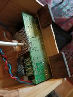
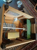
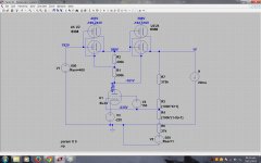
FWIW, I still have a yet-to-be-assembled Wroclaw Audio Force Najda (Latest frimware and modified for S/PDIF in by Nick) in the box (software is for XP... possibly Win7??)... an Orfeusz 206 also collecting dust (gifted to me by Nick, for lending some help). Also, a short stack (3@) of Cambridge Audio A1s (not v.3) modified for single-input S/PDIF DACs... bridged TPA3116 (@ 22/19VDC) may suffice for Subs....

Tube Bias question

Hello, just completed the bias on my tube amp, is it ok if one of the tubes have a very slight glow in the middle of it? You can only see the glow if the lights are off in the room (totaly dark). As well the amp sounds fine, and it takes about 10-15 minutes for this to happen. If the lights in the room are on, can't see the glow. The tubes are 6550's if that matters.

Thanks

Rino Odorico

Why does it work? Crossover with RF ferrite (wires) and 10nF polystyrene (bypass)

I have a question to ALL.

Two years ago I had cheap tweaks with my KEF Q100 coaxial speaker. It was trial and error.
[comment]
An externally hosted image should be here but it was not working when we last tested it.

[/comment]
attachment.php


1ª Why when I add a RF ferrite to the woofer wires I have more bass and faster?

2ª Why when I add a RF ferrite to the twitter wires I have more too much HF?

3ª Why do bypass with a small 10nF polystyrene the HF are less shrill and more pleasing despite being more detailed than before?


I have my hypothesis and I have read others but I still do not have it clear. Please, serious answers.

Bruno Putzey's G-Word with Hypex HPR and HNR 12 regs

FS: Bruno Putzey's G-Word with Hypex HPR and HNR 12 regs

I can't imagine anyone wanting it in the box it is in. But willing to send it as is.

The price will be same with or without the enclosure. (The volume knob is not supplied) I'd like to keep that.

150 Euro excluding shipment.

I do accept paypal.

In 100% percent working order. I just haven't installed a switch to switch between the two inputs.

Attachments

  • IMG20200212165457.jpg
    IMG20200212165457.jpg
    105.3 KB · Views: 274
  • IMG20200212165510.jpg
    IMG20200212165510.jpg
    124.7 KB · Views: 281
  • IMG20200212165524.jpg
    IMG20200212165524.jpg
    111.2 KB · Views: 281
  • IMG20200212165548.jpg
    IMG20200212165548.jpg
    90.5 KB · Views: 273
  • IMG20200212170452.jpg
    IMG20200212170452.jpg
    82.5 KB · Views: 268

Problems with bass in SigmaStudio and ADAU1701

Hey all!

I am currently working on tuning my DIY speaker, but I have some bass problems.

When I play at 80% volume, the bass plays very well and still is clean, but when I play it at 100% volume, the bass drops so much that it is less bass than what I had at 80% volume. As if I lower the volume for the bass, while in reality I actually increase the volume..

Has anyone experienced this too? Or does anyone know how to solve this?


Im using my fully custom FXtreme DB450 boards for this, which has the following specs:

------------------------------
-ADAU1701 DSP

-CSRA64215 BT

-TPA3116D2 x2 (4 channels, set to 26dB Gain)

-TPA6132A2 opamp (Between BT and DSP, Gain set to 0dB)

-AD8608 Precision opamp (Between DSP and Amp chips)

------------------------------

BTW: The high gain in SigmaStudio is for low-volume Bass Boost, as far as I know that is not the problem.

Note: Got it all fixed, there was a problem in my design..

Attachments

  • Sigma-FXtreme-DB450-4CH.png
    Sigma-FXtreme-DB450-4CH.png
    194.5 KB · Views: 798
  • 20191024_113507.jpg
    20191024_113507.jpg
    1,009 KB · Views: 716

ESR in speaker filter refurbishing...on the cheap way

Hi,
A buddy want to swap his 40 years old lytics...one speaker seems weaker whatever he îs standing in his room
Budget is a concern and some capacitance values in serie are highs.
Being in CE, I imagine some Mundorf lytics plain serie should cop, but I will measure the capacitance of the caps
Does capacitance move for lytic serie caps after 40 years...higher, lower ?
There is also no bypass, I have eventually some old styrens from philips I can give him...but is it good to mix a slow esr cap with a very low one of a tiny capacitance ? Seems an old way to bypass with 0.1 uF but is it still usefull todaý?
Cheap MKP in the 2 numbers range may fit on the pcb...but often I found it brighty if I remember from my limited speaker experience ?
I thought MKt that ESR lies between lytic and mkp are cheaper, but is that not also colored as the russian K73-16 are ?
What could I do to stay cheap? Bypass ? Cheap mkp or expensive Mundorf , generic mkt? ...
need to be axial for the pcb.
Sorry too much questions...no polemic please, just what was your experience to stay cheap and good enough either please?

Industry leading software in speaker driver design

Hello guys,

I am starting to learn all about designing 40-50mm headphones drivers and large studio monitor speaker drivers.
I want to know what is the absolute best and most professionally used software in this field.
Now I understand that “best” is subjective, but I believe that there are softwares that are more professional and are in a way leading the industry of speaker design. (Headphones and Studio monitors both)
Any recommendations?
Your help will be greatly appreciated!

Best Regards,

Tom

Tip needed - resonating

My DIY sub design is pretty good, but if you go too loud (and not *that* loud), the bracket that holds the voice coil starts rattling a little, and indeed I think there is a tiny bit of space somewhere.

Is there some fix recommendation for it, or is it 'start over'?

For example: is there some recommended sheet of maybe compressable rubbery material I can just squeeze into the gap and hope it'll stop the final bit of vibration?

noname loudspeaker – a polite request for help in identifying

Hello,
I have a polite request for help in identifying loudspeakers that I bought "for a penny" 🙂. I bought them without the ability to check/look inside, mainly due to the rubber speaker suspension and optically good condition of the enclosures. Maybe someone had something "like this" once in his hands and knows what it is ?
Going to the point:
- woofer: 16cm in diameter, magnet 9cm in diameter and 1.8cm high, rubber suspension (with inscription SR161/2), holes in the basket sealed with factory fabric, dc resistance approx. 3.6ohm, poorly visible designation CKS 7x87-378 U3 on the magnet foot (not all signs readable), the speakers were originally mounted using a black tar-like sealing agent:

- branching filter: designation 001160 30A6, Frako ETF 7,5uF and 15uF capacitors, 9217-037 small coil and a second one in the back, wound using a trafo core and epoxy-impregnated (with partially illegible designation xxx201), resistor 8,2ohm:

- tweeter: absent, only 12x12 cm hole with 10x10cm mount remained;
- housing: 40x22x20cm, made solidly, speaker fastenings made using M4 threaded rosettes pressed from underneath into the front panel:


- connections: admittedly with the proud name "Magnat" but according to me non-original, quite crap (especially on the side of soldering - or rather its absence - see how "expertly" you can connect the wires), their holes in the housing seem not to be factory-cut:

- no company sign, no other indications.
I have tried but unfortunately nowhere did I find any information about CKS speakers. I am thinking about restoring these loudspeakers, which is why I are looking for some basic information.
Best regards,
Pawel

Turning a weird headphones amp into a preamp

I was about to make the famous Rod Elliott's project 97 to drive a TDA7379 (that I'm yet to do) when I remembered I made a headphones amplifier years ago (it was never used apart from me checking it worked) by joining 2 different schematics for different uses, so I thought: could I turn that one into a preamplifier? What should I modify?

1-Do you think changing the output components values into the ones that P97 have is enough (6r8 to 100r, 220uF to 10uF and 10k to 100k)?
2-Should I remove that 1uF between the inverting input opamp and the Baxandall tone?
3-What about input components, should I modify those?
4-The headphones amplifier was made to use a single 9v PS, do you think it's possible to modify it to use a dual supply? Or it isn't necessary (I think it isn't)?

Or should I leave it as it is?
Or for some other reason it isn't suitable?
Or should I just make the P97 and stop bothering!? 😀

Here are the schematics:
The weird headphones amp:
ampcd-1sch.JPG
ampcd-1valoresPDIYA.jpg

The P97 just in case:
p97-f1.gif
p97-f4.gif

The TDA7379 shcematic from the datasheet (don't know yet what to modify ) :
DBdatasheet.jpg

Drive Board

Hi All. I have a Star Sound 6500 amp. I stand to be corrected but I think it is a copy of the Atomic 5K.

Amp Power supply section.jpg

output section.jpg

Another tech tried to repair the amp but just messed it up. I got the amp with the drive board missing. the guy damaged a few tracks to the drive board and also broke the vias. I was able to trace most of the track but just cannot for the life of me trace just one track. this is on the center pins the one that carries the voltages. Now on the drive board this is pin 6 that goes the the op amp U4 on pin 7.

IMG_20200212_163214.jpg

Now I need to find out on the amp board where does pin 6 go to. Does it join with pin as it looks like it does.

IMG_20200212_163310.jpg

TubeCad boards and parts

Sold

This item has sold.

I have the following TubeCad Boards with parts for sale:

PS1 power supply with TubeCad supplied parts…..$65.00

Aikido Octal Dual Mono pre-amp boards. 2 boards with TubeCad resistors and caps…$85.00

Both include construction guides. Note that these are just the parts supplied by TubeCad, other parts are needed for completion.

Pricing includes shipping. PayPal (gift) with US shipping only.

Attachments

  • IMG_0347.JPG
    IMG_0347.JPG
    129.3 KB · Views: 201
  • IMG_0349.JPG
    IMG_0349.JPG
    121.3 KB · Views: 206

Siglent Programable Power Supply

Sold!

This item has sold!

I have a Siglent programable power supply for sale. Model SPD 3303c
This is a 3-channel programmable supply with 2 variable channels and one fixed.
The variable channels are 0 – 30 at 3 amps each.
The fixed channel is selectable for 2.5, 3.3, and 5V at 5 amps.
$175 includes shipping.
PayPal (gift) and US shipping only

Attachments

  • IMG_0338.JPG
    IMG_0338.JPG
    102.7 KB · Views: 140
  • IMG_0340.JPG
    IMG_0340.JPG
    110.1 KB · Views: 145

Altec-advice sought for amplifier

I have a triamped main system using the Altec Model 19 parts in an MLTL cabinet with the Altec 416 alone in the 15 cu ft cabinet. I have been driving the woofers with a JBL 6290, way too much power and I think there is a better choice for the 416's.
I use a Pass F5 on the horns and have a AMT1 used as a super tweeter, using a variety of smaller amps for that.

The sound is good (I may remove some stuffing in the cab as an experiment).
The 416's and MLTL keep the lower register effective and there is no "bump" at 100 hz ->150 hz, as is typical for the stock cabinets.

What I'm seeking is a good amp design that can control the Altec 416's and is a better fit than the JBL.

Akai AM-2250 fault

Hi, I have an old Akai AM-2250 amp. Some time ago it stopped working through one channel. After asking around (on this forum a while ago) it was suggested that the STK amp unit was probably the culprit, so I got a new STK465 and recently got round to replacing it. Having done so, the same problem persisted.


I then noticed that a fuse had blown - there's a bank of three fuses in the middle of the board, and one of these had failed. It's a small 20mm 1.25A fuse, so I bought a pack and replaced that. When I turn it on, there is a loud buzzing coming through the channel that didn't work, which lasts for about 2 seconds, then the fuse blows again. I tried it with two new fuses, same each time.


I'm not technical and at the end of my expertise with this - this is a last attempt to find out what could be causing one channel to fail and the fuse to blow. Any suggestions on what to look for, or what could be the issue?


Thanks for reading 😱

Pioneer M-22 class A amp mistake in service manual?

I recently gave this amp a full rebuild, having replaced all caps (except the large filter caps), all transistors and the four trimpots.

Now the manual states the DC offset needs to be adjusted to 80mV.
I have a hard time believing that to be correct, can it be that it is just a mistake in the service manual?

I now just ignored it and adjusted it to 0mV and it plays fine.
There is just an - I assume - unrelated difference in temperature at the right and left side of the amp, the left side heat sink warms up to about 65 degrees, while the right side goes up to around 55 degrees.
The bias is adjusted to 850mV according to the manual and it stays stable at both sides.
What would cause that relatively large difference? The power supply stage only at the left side of the amp?

Some pics of the rebuild;

g6nXkf3.jpg


cjOQqFZ.jpg

Technics RS-TR373 Tape Deck - associated Schematic wanted

Under
TECHNICS RS-TR373 Service Manual download, schematics, eeprom, repair info for electronics experts
is to find the service manual.
Unfortunately the mostly defectice parts R406 (27R), R407 (1R), C423+C424(470/10) are not to find in the genuine schematic in this values - go to
Tape deck has no audio output (Technics RS-TR373) | Electronics Forums
Are there missprints present or are there different versions ?
Best thanks for advices.

Push-Pull EL84 amplifier

Hi, i want to build a simple el84 pp amp. I have a 8k output transformer (without UL) 2 el84 and a ecc82. Is this a good schematic?

TUBE_AMP3.jpg

Has the ecc82 a proper gain for a input a .5Vrms at full power? If i have 2 nputs, one a CD player, and the other is a Computer, which has a minor output, how can i have a equal level at the same volume?

Thanks for any ansower and sorry for any grammatical error, i'm an italian student and i don't know english very well.

Polymer vs. electrolytic caps in phono pre

Looking to change out cheap electrolytics in an ART DJ Pre II phono preamp and wondering if there are opinions on whether switching to polymers or just using better electrolytics would be best choice.

I like the sound of the budget ART and willing to experiment with a cap change to see if it can elevate the already decent performance. Whether or not this is a wise thing to spend a similar amount on caps as the whole unit costs is not really for debate.

I have only come across one user who switched out some of the cheap electrolytics with some Panasonic OS-CON polymers and commented "sounds really good now".
IMG_3970_zps4gw1ijer.jpg

A very knowledgeable hobbyist has suggested the polymers in such a circuit might sound cold and dry so seeking more opinions on whether this might be the case.

In the end, I realize the only way to find out is to do the swap but before I commit I would appreciate any expert opinions on polymer vs. electrolytic choice.

An interesting thing happened while gluing a voice coil..

On over-excursion of a woofer(s) run in Dipole, there was a loud "POP"..

Turns-out it was the cone hitting the VC leads which were sloppy-large: plenty of VC lead, but the natural bend down to the VC sagged to low: on recovery the cone slams into that "sag" from the VC lead.

Fortunately there is enough lead there to sort of "lift and separate" (like a bra on an old woman :yuck: ) and still allow for more than enough excursion (even when pushing well beyond the gap).
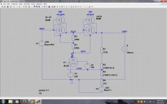
My solution then was to put some felt tabs on the frame (inside/underside) near the driver's terminals and "lift/separate" them to those felt tabs. This puts the lead's just coming off of the driver's terminal stuck to those tabs.


..so, I pull-out the "crazy" glue (Cyanoacrylate), use gloves (disposable), glue the leads and press them firmly on the felt tabs for almost a minute.

-and the interesting thing was: it didn't hold.. at all. (..stuck wonderfully to the gloves though).

I don't think I've ever had that type of glue NOT work before, but something about the VC (flux?) - just wouldn't work with that type of glue.

The fix was easy of course: hot glue gun. 😀

-burnt my finger a little though (..4 times - it was 2 drivers). 😱

Finally a DIY PCB procedure that works

After many years of trying to make PCBs and only having limited success, I finally found this product that works straight out of the box and is clean and easy to use.

PCB Fab-in-a-Box Kit — Cool Components

It relies on the same toner transfer principle that is commonly advertised but uses a clay coated paper that guarantees 100% of the toner is transferred to the board.

The producer acknowledges that the toner image may not be 100% opaque and addresses this with a Green Foil that ensures solid traces from a less than solid toner image.

Top up paper and foil is readily available and won't "break the bank".

Results are better with the recommended laminator but I did get good results with a household iron.

It's well worth the money in my opinion.

Help designing regulated power supply

Hi, I am designing a new regulated power supply for my lab since my heathkit IP17 sometimes isn´t up to the task at hand.

It is a (not so) conventional regulated supply with series pass tube(s), I´m using two 6336 (which I already have at hand) in series since I want 0-600V and their max Vp is 400V. The problem i´m having is the control tube, which has to be able to handle 595V on its plate with the output set at 600V to -160V with the output set at 0v. If I want to use a usual voltage reference at the cathode of the control tube, assuming 60V drop at min output, the tube should be able to handle 595-(-220V)=815V anode to cathode. The only tube that comes to mind able to handle near that is an EL34 (800Vp max), but obviously there must be a better solution. I thought about making the cathode voltage reference vary in accordance to the output voltage but somebody might propse something better.

I attached the LTspice simulations so you can see what I´m talking about, voltages on top of series pass tubes are anode to cathode and grid to cathode. If someone can come up with a solution it´d be much appreciated.

Attachments

  • 600V 250ma.jpg
    600V 250ma.jpg
    466.1 KB · Views: 928
  • 0V 20ma.jpg
    0V 20ma.jpg
    468.1 KB · Views: 897

1st order slopes and 1/4 wavelength spacing

I understand the utility of <1/4 wavelength driver spacing. I'm also aware of rising response of woofers and the need to cross well before cone breakup. Unfortunately, there are WAY more things that I don't know than those that I do know!

I'm thinking of making a WAW with an 8" full range and an 8" woofer. I know this is the multiway forum, but I respect all opinions, including those of the multiway way guys and I think the question is more appropriate here. Mods please feel free to move if you want.

Anyway, If I put the 8" full range on a baffle at about 90cm height and the 8" woofer centered at about 20cm, they'd have say roughly 70cm separation -- dictating about a 100 Hz cross with the 1/4 wavelength rule.

Partial motivation would be to get the floor reinforcement with a sealed cabinet. My question is, with a 6dB/octave, 1st order filter slope and the sealed box, would the falloff be fast enough that I don't hear 2 sources at, for example, 300 Hz?

I guess the jewels of the question are: does filter order greatly affect acceptable driver spacing?

Muchas gracias. Hope everyone is safe from the coronavirus.

Thinking about a small active monitor. Phantom Reactor DIY?

So basically I'm a little bit in love with both the Kef LSX and the Devialet Phantom Reactor. They are both small active systems, but work quite differently. The Kef LSX is a proper high class speaker, where the Reactor is more of a party boombox on steroids. 😀

I think it's amazing what the Reactor does, and enjoy it more than the LSX.

Anyway, I've been thinking of doing something like this, but DIY. I have two Hypex Fusion FA123 amps. I would mount them in the stands to maximize the space in the speaker itself.

Because of the small size, I'm looking at woofer-passive combinations, to ensure proper SPL at lower frequencies. I don't think I can match the Phantom's low end, but I hope slightly more than the LSX is possible.

Any ideas for a woofer?
I could also do a miniature subwoofer with a fullrange, would look better too.

Extra edit: the FA123 has two 125watt amps and a 100watt tweeter channel that I can not use full-range.
When I would go for miniature sub+fullrange, the tweeter channel will be left unused. (Or I might use it for a rear firing supertweeter) When In would go for a tweeter/woofer combination, I can bridge them.

The Tang Band W8-2314 is also interesting. Have to see if it works well with passive's. It is too big though.

Is this a useful amplifier heat sink?

My local recycler just got in a couple dozen of these Thermoelectric-Peltier Cold Plate Cooler & Heater - CP-036

They don't look like they dissipate a huge amount of heat but I am not techy enough to understand the datasheet. What do you think? These ones have the liquid cooling option and the temperature sensor and fan controller boards, I think its intended use was to refrigerate liquid. Maybe a water dispenser or something like that? They want 15 bucks each.

What's special about the BorderPatrol USB DAC?

I think this one is pretty old school :

TDA1543, NOS, no output buffering, tube power supply, etc.

Seems to be getting attention on CNET (Steve Guttenberg)...
A kinder, gentler sound for digital audio - CNET

...AudioStream ...
BorderPatrol USB DAC | AudioStream

and (just yesterday) on Guttenberg's YouTube vlog:
YouTube

The "SE" version is pretty $$ (at $1300).

I'm sure many here on DIYA are waaaaaaaay past DACs like this in terms of their own in-house stuff.

Soekris, Ultimate NOS, etc. Even souped-up mods of Chinese cheapies are pretty good (e.g., 8x TDA1387, etc.)

In any case, the subject question stands: why are pop-press reviewers raving about this design?

The company has the specs and claims on their web site incl:
To our knowledge, BorderPatrol is the only
company applying tube rectification and
choke input filtering to digital circuits.

Port resonance in a two way floorstander?

Guys I putting together a floorstander to use some car audio drivers I have, more as a test of the drivers against some more conventional home audio drivers than anything else.

The speakers in question are JL Audio C7 components, made in Germany by Kurt Muller and so aren't the usual crap one finds for making noise in cars but in theory good, hi fi drive units.

The common saying is that car audio components are overpriced, when good, compared to the usual home audio DIY brands and I would like to test this.

The advantage of using these is that they already come with an very good quality crossover all made up by the manufacturer, which simplifies things for a beginner I think.


Whilst I have modelled and built a few subwoofers and am comfortable with WinISD and Bassbox Pro, this will be my second attempt at speaker building with the first being a pair of bookshelf speakers using some other car audio drivers.

When porting a subwoofer I have always tried to keep the resonance frequency above the low pass filter crossover point, this seems impossible with a full range design and so how worried and what can I do about port resonances?


Should I try and push them down as low as possible, with a big port, or as high as possible, with as small a port as air velocity allows, or something else?

Cable capacitance

I always been lazy with math i am a screwdriver person

So before i start digging in my rusty math i seek quick advise from Solid state people

In a class AB amplifier which has most of the times feedback lets suppose that one user uses cables that for some reason have some or excesive capacitance

--is the capacitance itself that introduces a filter in the circuit probably effecting high frequency response ? lets suppose that the cable has 10-20-50-or 100pf capacitance does this form a filter that is in the audible frecumncy and that will effect the total result ?

--is the relation of feedback involved and this will after all effect the total result ?

kind regards
Sakis

Dayton RS180-8 & Vifa XT25, what would you do?

As the title says really.
I've got a pair of Dayton RS180-8 7" and I have a pair of XT25 on the way.

What type of speakers would you build with those?

I don't mind floorstanding speakers as long as they aren't huge.

I've been trying to learn speaker design software during the day, but I would prefer not reinventing the wheel if there already are good designs with these drivers out there.

And I have spent the better part of 2 years or so getting decent at KiCad and PCB design. Unless necessary, I'd like to avoid learning another set of software's that I'll use for most likely this one project.

I have one pair of each so a dual 7" 2.5-way or similar is out.
Grateful for any and all help and advice.

JL 500/5 low ohm light 2 seconds upon turn on

Just purchased a used jl 500/5 . Was told working all well.
Brought it home did a power test no speakers hooked up to it .would turn on but the low ohm light would aluminate for approx 2 seconds then fade away green power light afterwa5ds, I tested each channel with a 4 ohm bookshelf speaker. All channels work well gain works,channels clear sounds equal loudness . When amp powers down low ohm light turns on right at the end ?

Also I removed the cover and powered up, all green leds come on at same time same speed .same brightness.

I called jl audio tech no real information gained .amp was too old for accurate knowledge. He was leaning towards internal short.

Nearfield Measurement - adjustment for multiple ports

When taking near field measurements what is the correct way to sum the output of multiple ports and the cone into one single response graph?

From Jeff Bagby's "White Paper - Accurate In-Room Frequency Response to 10Hz" he gives an example for adjusting for one port: The smaller of the two, usually the port, will need to be lowered in SPL (dB) because its smaller area will apply more pressure on the microphone making it appear louder. Its output needs to be lowered by the ratio of their areas using this formula: Lower the port by 20 Log (Port Diameter / Cone Diameter). So, for our 6.5” woofer, with its 5” cone area, working with a 2” port, the port output will need to be lowered by 20 Log (2 / 5) = -7.96 dB, or roughly 8 decibels"

For dual ports he give this example: for dual ports, find the total port area of both ports and determine the effective diameter for the combined area. Now, take the measurement at only one port, find the ratio of the total port diameter to the cone and make the calculation and then add 6dB. So, for our example, if there had been 2 – 2” ports then the port output would be lowered by -7.96 + 6 dB = -1.96 dB. For dual woofers and a single port we will need to do it the other way around and subtract another 6dB from the port output.

However, I'm not understanding this. If I calculate the total port area of the two ports you get a combined area of 6.28sq inches or an effective diameter of 2.28". If I then calculate the SPL adjustment by using the ratio of diameters (effective port/cone) = 20 Log (2.82/5) = -4.97dB. If I then add the 6dB I get +1.03dB.

In my particular situation I have a woofer with an effective diameter of 4.375", two ports of 0.625 diameter (front), and one port of 1.25" diameter (rear). I am trying to apply the correct adjustment to a port reading so I can stitch the woofer and port measurements into one SPL graph. I think I can figure it out once I understand how to do it correctly.

Centralized multiple zones from a PC

My current setup is as follows:

ThinkPad to 3x Startech 7.1 USB cards that feed 12 zones (mostly stereo, a few mono).

Running MS4L, which is an LMS/SS-Lite based setup. It lets you do the following:

1. Separate out USB sound cards into whatever mix of channels you want. You can take each 7.1 card and have 8 mono channels, 4 stereo channels, or a mix of both (e.g., 6 stereo and 2 mono).
2. You can have zones that overlap in inputs, so you could have a 1st floor zone and a living room zone.
3. LMS plugin support for Airplay, Spotify, etc.

But....

It is a pain to setup. When you have multiple USB interfaces, they are assigned to channels in order of boot and can end up mixed if you accidentally pull a cable. You have to walk through and figure out which channel is which manually which is tedious as hell. Etc.

So before I bang my head against the wall setting it up again, I want to see if there is something better.

Key requirements:

1. Let me split soundcards in the same way into multiple zones
2. Spotify support is absolutely required
3. Interrupts for doorbell and other alerts (mp3 or other)

Nice to haves:

1. On the fly synced grouping
2. An easier install
3. Room correction for each zone
4. Headless operation
5. Airplay and UPnP support

I looked, and most of them are RaspPi based (e.g., Moode, Volumio, Max2Play). I could do this, but 12+ Raspberry Pis isn't that cheap either and it feels a bit silly to have a bunch racked up instead of one more powerful system.

PC Based 5.1 Active XO system.

Need some clarification from the experts here...

I am trying to assemble a 5.1 active XO, pc based media player...

I already have the 10+ channel amplification for my 5x 2 way speakers, and I was looking to buy 3x ADAU1701 DSPs to feed the amps, but realized the whole media I consume is PC based (netflix, plex, spotify, etc.), and that I could use my PC (Equalizer APO and rePHASE) as crossover, but the problem is that I need a 10+ channel DAC or multiple soundcards... So, what choice do I have?

a). 10+ channel DAC = too expensive, and beats all the purpose.
b). Multiple USB sound cards = this would represent a problem to configure multiple outputs without delay and configuration problems.
c). Get a 16 channel USB interface like the Behringer UMC1820.

Would this last alternative work? When I plug the UMC1820 will it be recognized with EqualizerAPO? As an USB interface, all the sound output's thru this interface? The price is very atractive, buty I don't what to spend that money if it's not going to work for me. I assume hte sound must be outputed as PCM, so no bitstreaming, and I will be limited to 24bit 96khz (not a problem and I will probably use 48khz).

So the chaing would be:

PC > UMC1820 > amps > tweeters and woofers

I am not looking uber audiophile quality, I just use it for movie watching and some music, but not critical.

Thanks in advance for your help!

16 ohm speaker for OTL amps

Hi all.
I am currently in the progress of restoring a pair of (good quality) DIY Futterman OTL's.

Being OTL's, speaker impedance obviously becomes critical, and I am considering building a pair of dedicated 16 ohm speakers for them as a side project. I will need adwise though, but first a couple of pre-requisite informations:
The speakers will be positioned in a living room with open access to two adjacent rooms with a combined footprint of around 750 sq.feet. One speaker will have to be placed in a corner but this haven't been a problem in the past, as there's plenty of room for the sound to escape into.
Sound level is fairly low, hardly ever above 90 dB.
Distance between listning position and speakers 10 to 12 feet, with the same between them.

So, what do you suggest, look for 16 ohm speakerchassis which predominantly exists in the PA industry and design a 3 way say 10"/6" with a 1" horn/bullet tweete?
Or build something with two units in series, like an isovent/isobaric solution in the bass, D'appolito for midrange and two tweeters, potentially with one facing rearwards?

Just throw in your suggestions.

Regards
Thomas

Ultra low noise PSU on e-bay

LT3045 LT3094 Positive and Negative Low Noise Regulated Linear Power Supply New | eBay
LT3045-LT3094-Positive-and-Negative-Low-Noise-Regulated.jpg

Any first hand experience or measurement with this PSU board? It uses the LT3045 and LT3094. If those were genuine IC, the noise performance should be very good. The small heatsink may need a 30-40mm cooling fan if more than 100 mA output is desired. The small board size is very attractive for low power, phono stage application.

Humming - ground loop or other problem?

So my situation:
- 1000W class D subwoofer amplifier (velodyne microvee)
- If I use my mobile phone as audio source- works perfectly
- If I plug it into subwoofer out on my receiver (denon x4500H): pretty serious hum.

So clearly this 'sounds like' ground loop hum, but:

- Second subwoofer has no such issues, so the receiver is probably fine
- Ground Loop Transformer has maybe a little effect but not much
- Shortening cable length down to 1m, swapping power polarity, same power strip as amp.. all no luck

My best guess is that the amp is broken, perhaps dried up caps (and in fact I used ESR Meter to check the ones that are easily reachable and one cap is definitely 'dubious'...)

But does this make sense? Why is the thing working perfectly with the mobile as audio source, but not with the separating transformer? What else could this be?

For sale: new unused ERSE Super Q 2.0 mH inductor pair

Up for sale is a pair of new unused ERSE Super Q 2.0 mH inductors. These are solid core devices wound with 16 AWG wire and have DCR of 0.143 ohms. Parts Express sells them for $22.48 each.
ERSE Super Q 2.0mH 16 AWG 500W Inductor Crossover Coil
The price is $32 for the pair + shipping and PayPal fees. I have 5 pairs available.

678664d1525463436-sale-unused-erse-super-2-0-mh-inductor-pair-erse_super_q-jpg

Attachments

  • Erse_Super_Q.jpg
    Erse_Super_Q.jpg
    166.3 KB · Views: 257

Hilarious descriptions in audio sales literature

This cracked me up today browsing... Goes beyond poor translation

"The tone is different from the silicon tube, and it is different from the tube and the field effect tube. It has its unique charm and style, like lobster and chicken soup."

#Aliexpress NZ$ 94.11 | The sound is fascinating pure class A single-ended tube output preamplifier board, the sound is transparent and lingering LG267H
AliExpress

What strange comparisons or superlatives have you seen in descriptions for audio equipment which made you chuckle?

Feedback resistors

Hi,

It is written page up and page down about sonic traits of using different types of coupling capacitors. But in a regular ss power amp, does anyone have any experience in changing feedback resistors for no other reason than sonic improvement?

I got to thinking about this when I swapped the reasonably good Jantzen Superes 10W resistor for Duelund Cast resistor for the tweeter series resistor in my diy speakers. I have done cap swopping a lot, but I have not tried that many resistors.

I found the Jantzens a real upgrade over standard ceramic types, but I was really surpriced at the difference the duelund resistor gave. More so than capacitor I would say.

Help with understanding power distribution in actively crossed over systems ?

Hi. I need help with understanding actively crossed over systems. The thing that confuses me is if i for example use 40w woofer and 20w tweeter and have active crossover how do i match the levels? Correct me if I'm wrong but if i use lower power amplifier for tweeter than woofer than tweeter will have lower gain. So am I supposed to use same amplifier for woofer and tweeter and let the crossover handle power distribution or am i missing something?

LRS350-48 supplier?

Would anyone know where to buy a LRS350-48 PS? I cannot get one from Meanwell in the UK as they will only supply with a VAT number (Business ) which I do not have as just looking for personal use. There are companies called Agouk and Ledlightingsave which have identical web page so think it is the same company. Just want to avoid rip off's without paying silly money for it. Thanks.

Cambridge Audio D500SE faulty analog out, probably DAC - asking for advice

So, just got this player quite cheap, in very good cosmetic condition and laser/transport seems fine, too. Owner claimed it was working fine with digital out, but no analog out. I don't have a standalone DAC to test, but I believe him ,as all the rest is 100% true. Checked analog out signal path and in fact no audio is coming to the opamp filter stage at all. Just some very, very low static signal (my scope has trouble triggering that waveform for so tiny its amplitude), when amplified on poweramp with preamp, it sounds like static, with very, very low and far away hear something of the music it is playing on the CD.

I googled around and got some schematics, but the important section, the DAC, is not of SE edition ,has a different DAC. This one uses CS4391. I checked all digital signals from transport with my scope and they seem fine (SDATA, SCLK and LRCLK), although with a bit of HF noise on the top of the wave form (but I guess it's normal, they all look quite good), and yes, they do arrive at the DAC. Also, IC seems to be well soldered and nothing measures odd, except for one thing: the resistance from RST pin to +V, was like 200 ohms. When operating, voltage was measuring only 2,78V, which is weird. It has a soft start delay and hardwiring it to +5V made the output static a bit more intense, but nothing solved.

Started to research and found a lot of reports on the internet of the CS4391 failing, especially the lots produced around 2000 (well this player is from 2002...), and people reporting static noises. To be sure, I substituted all three passive components which make the soft start reset circuit, nothing changed and they all measured good.

So, I suppose I can conclude almost 100% sure that the DAC IC is toast??


Also, what is more important: if the IC is fried, which is very likely, the problem of taking it out and soldering a new one arrives, as it is tiny, I'm good at soldering, long years experience and have a good soldering station, but very little experience with SMD work. I mean, I don't say that I couldn't get the stuff needed and try. But there's a certain risk that I might damage some pcb pads and that's a serious problem to fix, some have traces under the IC...

So, I guess I have two options here:
1) get a new CS4391 (or a couple of them, should something go wrong) and take the risk, or, as I was thinking in modding this player for myself,
2) go the total adventure route and build a DIY DAC for this CD player??? What do you think? Has someone done this with this kind of transport (it outputs SDATA, SCLK, LRCLK, but also a normal one wire digital signal + ground, which goes directly to the digital outs on back panel, so there would be two kind of interface available to connect to custom DAC).

There's one thing against building my own DAC board (whatever kind): I was really curious to listen to this player with the original DAC from Crystal, as it got some nice reviews and was curious to compare it against my loved and modded Marantz CD40 (like: modern against vintage 😀)...

One the other hand, a custom made DAC might be much better and make this player far superior? Now an important question: is the transport worth the hassle? I mean, they do have a nice copper box around the servo logic with big, blatant words (and ICs shown for that in schematic seem state of the art of that time) and I do like the front panel (which seems in great shape, no display issues, like they often report), BUT... the KSS-213 is quite basic and cheap, at least when we compare it with the great swing arm transports, for example, and this one seems quite noisy, it even makes some slight ticking noise when the CD runs, like if it was something uneven (don't think it's the CD...). Although seems to read and track fine.

Thanks in advance to all opinions and hints I get, I'm feeling a little bit lost here right now...

Sinewave oscillators: 1. The gain control block

I would like to launch a series of discussions about the design of low-distortion sinewave oscillators.

There are already a number of threads dedicated to the subject, this one being a typical example.

Together, these threads represent a huge amount of information(s), but they tend to be large, messy, and mix up new ideas, old designs, SOTA designs, and revolve about all aspects of such oscillators and sometimes unrelated subjects.

With thousands of posts, any relevant information tends to be drowned in an ocean of "noise".

Here, I will discuss each aspect in turn: gain control will be the first one, but I also intend to discuss topologies, active elements (gain blocks), amplitude acquisition and filtering, passives, etc.

I am not interested in the current state of the art: this can be found on the net, or here, without too much effort.
I would like to see new approaches, and they could be new takes on existing solutions, or completely new solutions.

I am going to illustrate that point, based on the classic jFET VCR example:

attachment.php


First is the classical implementation, with all its known issues.
This basic circuit can be improved by using a more clever summing scheme, to improve the accuracy and speed of response: SOTA.
Both the previous circuits suffer from a residual non-linearity and limited dynamic range.
It would be interesting to find a corrector network, to lower the distortion and improve the dynamic.
Only the last circuit would qualify, because it brings something new.

I am going to prime the discussion by presenting a gain control based on lambda/Early effect.

The Early effect, and its FET counterpart, the channel modulation are non-linear effects.

They are generally seen as a problem, because they increase the THD of amplifiers, but would it be possible to take advantage of them to create novel types of VCA's?

The answer is (apparently) yes. This drawing illustrates the principle:

attachment.php


The output resistance of the transistor can be modulated by the collector current or the Vce.
The dependence on the Vce is what causes the non-linearity in amplifiers, but Ic provides a convenient, direct means of controlling the resistance.
Of course, using a single transistor would be somewhat impractical.
A push-pull configuration seems ideal, since it neatly solves DC issues etc:

attachment.php


Now that there are two active elements, the Vce term disappears, meaning the synthetic resistor becomes linear (assuming the Early law is cast in bronze, which is not exactly the case unfortunately).
Things are not that simple though, mainly because complementary transistors are a fiction that doesn't hold in reality (in silicon at least).
Parameters differ widely, and Vaf (Early voltage) is heavily affected: PNP's have a much lower Vaf than NPN's.

The solution is to go all PNP:

attachment.php


This is a first, half-practical example. I will examine later its shortcomings, and possible remedies.
I will also introduce a figure of merit, to evaluate more objectively the various alternatives.

The simulation shows an amplitude sweep, from 6Vpp to ~0.6Vpp

Attachments

  • SWO1.png
    SWO1.png
    12.6 KB · Views: 698
  • SWO2.png
    SWO2.png
    6.7 KB · Views: 643
  • SWO3.png
    SWO3.png
    10.7 KB · Views: 621
  • SWO4.png
    SWO4.png
    69 KB · Views: 639
  • EarlyVCAbip.asc
    EarlyVCAbip.asc
    3 KB · Views: 56

NJL4281DG NJL4302DG -- discontinued Thermaltrak FS

Datasheet still available on OnSemi's website -- discontinued by OnSemi about 5 years ago.

NJL4281/4302 15A/350V 230W hfe=80-250 cob=600p
NJL3281/1302 15A/260V 200W hfe=75-150 cob=600p

Rochester has the NJL4281 on offer @$2.59, no offer on the complementary device.

4 each NJL4281DG/4302DG (8 devices) $10, shipping conus $7.45, row $14

PM if interested.

Toroidy 300VA 50-0-50...for JLH Hart KIt Monoblock.

Not at all confident about this...so need to check that this will do the job.

Have found this standard grade Toroid on the Toroidy.pl site.


TTS0300 - Transformer TS300VA/230 - voltage to 50 V - Shop Toroidy.pl


Needs to replace a burnt out ILP 73033 (300VA 50-0-50) in an 80's built

Hart Kit JLH Monoblock amp.


It isn't audiograde.....but understand that the original ILP wasn't audiograde either!

THD controlling

Hi,

Edit: R2R DAC emulation implemented
Sound Distorter R2R 0.2.37.53


Many times while considering to order a new DAC, that should better than a previous, I asked myself how low distortions I do need practically. The question was always important just because any next DAC requires next growing budget. I believe the equation is not surprising for anybody.


So I wrote a tool to simulate controllable distortions from -110db to - 40db and to add the distortion to a software player. Sound Distorter

Also in the background I've been thinking about no-linear distortion in general.
Actually there is a set of audio equipment genres, such as R2R DACs, tube amplifier, with distortions noticeably higher than expected.
However the sound of such devices is often perceived as desired, not just specific. Ordering an R2R DAC (for instance) just to check the sound is not the best idea to me (at least), the experiment doesn't look affordable. So I think about whether it's possible to simulate the same specific distortions programmatically and compare the difference.

I would like some feedback if the subject is curious to somebody else.

Thank you,
Serge

Do I need a dummy load?

Alright, I'll start by saying that I don't know whether this is the appropriate place or the Class D forums, but here goes...

I'm working on a proof-of-concept idea for a mobile karaoke setup. I have two cheap, Chinese class D amps that cost me $22 and $30 respectively, the first one based on the TPA3116 that I bought a couple years ago and a new one based on the TDA7498 that I literally just got in the mail today. They both share the same extruded aluminum "Breeze Audio" case, but I suppose that's not terribly relevant. I'm sure many of you are familiar with these. The new one is definitely more hefty.

Anyway, my proof-of-concept idea goes as follows:
I can back my Jeep Cherokee up into any random field, parking lot, etc. and pop the tailgate, and within five minutes have a working PA set up. The back of the Cherokee is the "table" where I set my laptop and mixer and the two amps, the two 12" speakers (Panasonic RAMSA WS-A200's if anyone cares) go up on some cheap stands, a mic stand is set up with two mics on it, and an 8" monitor speaker (RAMSA WS-A80) gets set up on some kind of stand (still working this part out) with a USB 3.0 screen connected to my laptop in front of the mics. Boom.

So here's my question:

The two amps are both set up stereo. Obviously I want to use the more powerful of the two (TDA7498) to drive the mains. The monitor only needs to be mono though, so should I consider attaching a dummy load to the unused channel of the TPA3116? I don't want to hurt it, but these little amps actually seem fairly resilient. Let me stress that no signal will be put through that channel.


Add-ons:

If anyone knows anything about wiring extra power into this system via a couple deep-cycle batteries so I don't have to run my engine/alternator all the time and still have enough juice to get me through a night without killing my car battery, any info on that would be awesome. Ideally I'd like the extra batteries to charge from the alternator while I'm driving. Even better would be if I could run the power from them back into my car in case I have trouble starting it in the winter, but I have no idea how plausible that is.

I'm already taking the car power from a cigarette lighter and running it into a 24v up-converter to drive the amps. I've yet to attempt driving both at once, so I suppose another question would be whether I should invest in another up-converter that puts out like 10 amps and drive both amps off that, or if I can use the two I already own that put out 3 and 5 amps. Will that make a difference? What's the more efficient way to handle this? The mixer will also need to derive its power from the vehicle but it takes 15v so I know I'll have to buy a 12-15v converter, too.

The mixer is a cheap Chinese model as well. It's an "ammoon" mixer with five mic channels and one stereo channel, along with some on-board delay/echo. I entertained the idea of using a small Behringer mixer I already own but those take AC power and I wasn't sure if there was a workable DC solution.

Any comments/info would be appreciated. I'll do my best to answer follow-up questions.

Another Super Scooper Build Thread

I am selecting some 18" subs for my scoopers and I am thinking perhaps Celestion FTR18-4080F's paired with Bryston 7B's. I know that's a lot of money in amps but they are the only ones I trust so much from my recording background and I'm not very well versed in selecting LF drivers. I'm still learning what is "high end" for LF driver brands other than TAD and Celestion and what amps are more pro or consumer grade.

Bryston 7B
Description: Solid-state monoblock amplifier. Output power: 600W continuous into 8 ohms (27.8dBW), 900W into 4 ohms (26.6dBW). Gain select and sensitivity: 29dB (2.3V in = 600W into 8 ohms), 1V setting; 23dB (4.6V in = 600W into 8 ohms), 2V setting. Frequency response: not specified.

4080F
Nominal diameter 457mm/18in
Power rating 600Wrms
Continuous power rating 1200W
EIA power rating 800W
Nominal impedance 8Ω
Sensitivity 97dB
Frequency range 30-3,000Hz
Voice coil diameter 100mm/4in
Chassis type Cast Aluminium

What do you think? Any suggestions?
Projects by fanatics, for fanatics
Get answers and advice for everyone wanting to learn the art of audio.
Join the Community
507,489
Members
7,874,131
Messages

Filter

Forum Statistics

Threads
405,573
Messages
7,874,131
Members
507,489
Latest member
bobberhead56