I'm either having a massive brain fart or a stroke because I can't visualize the physical connections of a 4P3T switch as described in the excerpt below. Its driving me crazy, so I've come to you geniuses for help.
Can someone please create a simple wiring diagram in MS Pain, for example, of how this switch layout would be wired?


Thanks
Can someone please create a simple wiring diagram in MS Pain, for example, of how this switch layout would be wired?
Thanks
It has 4 inner pins and 12 outer pins.
You should have 3 positions when rotating the shaft.
Rotate the shaft to one side.
Measure from one of the center pins to the others.
The one that measures 0 is Your first position. Mark !!
Count 3 more and the fourth should make contact with the next inner center pin going the same direction...
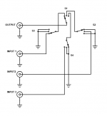
If You want to make the same as the picture, You'll have to make some jumpers...
You should have 3 positions when rotating the shaft.
Rotate the shaft to one side.
Measure from one of the center pins to the others.
The one that measures 0 is Your first position. Mark !!
Count 3 more and the fourth should make contact with the next inner center pin going the same direction...
If You want to make the same as the picture, You'll have to make some jumpers...
Sorry, but unless this is for use in a piece of test equipment with a noise floor more than 90 dB down, the added isolation is wasted.
Why not a 3P4T switch for probably the same price?
Then you could have a 4th choice if you wanted it and virtually identical isolation performance, but twice the reliability.
Any time you add switch contacts you give dirt and dust another place to attack -- fully 1/2 the reliability, over time.
Just my 2 bits.
Cheers
Last edited:
If the circuitry is high impedance this technique will make more of a difference. Switch-breakthrough is more of a problem in mixing desks than domestic HiFi as you don't normally have all the sources switched on all the time just to listen to one of them.
All valid points. The switch is for a tube preamp which deals with high impedance's. But like you stated, only one source is switched on at a time anyways. This is DIY after all and I just wanted to do it for fun to see it implemented.
- Home
- Design & Build
- Parts
- Help wiring a 4P3T switch