FS Pass B1 R2

Pass B1 CLONE direct coupled so without capacitors on signal path.
Dual mono output stage with low noise TPS7A4901- TPS7A3001 regulators with premium parts. Transitors have gold pins and can be easy interchangable.
Al 4 2sk170 are closely matched for minimum dc offset.
With 4x12vAC -0.5A transformer.
price 35€ without paypal and shipping cost.

Attachments

  • IMG_20180813_062103.jpg
    IMG_20180813_062103.jpg
    572.7 KB · Views: 330

74HC4052D for audio switching

Hi everyone,

I'm happy to ask a question for the first time 🙂

I'm designing a dj mixer and came across a problem with audio signals switching.

An externally hosted image should be here but it was not working when we last tested it.

Above is a part of a well known mixer that is using thoses 74hc4052. The signal comes straight from the output of a TL072 and goes to another op amp on every switch output. My concern is that the datasheet specify an input voltage from gnd to Vcc. So how does this ic can be used for audio signals since they are AC?

I'm sure i'm missing something, sorry if my english's bad and thanks in advance.

Cerwin Vega HFA21s (amph00009) schematics

Hi!

I have an Cerwin Vega! amph00009 (220v version of the amph00008) amp from a CVHFA21s subwoofer that goes into "protect" mode when powered up and stays there.
"Power" and "Protect" LED's lights up when its powered, and "Signal" LED also comes on when a signal is received, but it does not go out of protection mode.

From what I understand, this is a pretty common problem with these amps.
This particular unit has been repaired before and based on the reciept a diode, 2 resistors and 2 transistors was replaced. I was told that the sympthoms was identical the last time as well, and that the"Protection system circuit" was faulty.
Material cost for the 5 components was about 5$, total bill incl labor was 300$.
This was 2 years ago, but the warranty for the repair was only 3months.

So now I was hoping to fix this one myself.
Does anyone have the schematics for this amp, know what parts this "Protection system" consists of or where on the board this circuit is?

Best regards,

NorAndy

Some questions for F5 build

hi - could i ask a few questions regarding my F5 build?

1) on the variable resistors P1-P3, can some be reversed so that all three are facing the same way?

2) on the universal PSU, i bought some TO-3P diodes. In the guide, it says that it's recommended that i should buy an insulator to connect to the heatsink but these are made of plastic so why are they conductive?

3) there is a 3300pf cap. Can spec should this be? is it the X1/Y1 type or any high voltage metal cap is fine?

thank you very much

Class A input buffer

I like the sound of this buffer In my Nad C272 amp but, the question is, is it really clever to have 3 caps in the signalpath, first there is a 0,22uf, the output a 100uf bypassed with 10nf (seems high) and then finally a 10uf before heading into the gainstage..

Anyone see any improvement that can be made with this design by Björn Erik Edvardsen?

Can the 100uf be deleted? Or what the pro’s say?

Also there is a aluminium box screening this off from rest off amp? Is it so sensitive part that you need it? I have now removed it due to the heat.

The 667/647 runs extremely hot now I can add (like cooking!) and heard from many repairguys that they often have to replace them.

Thanks for any help. I’m a beginner in this and like to learn more.

Attachments

  • 272EF11F-E6AD-482A-BF86-E4875FABCF5E.jpeg
    272EF11F-E6AD-482A-BF86-E4875FABCF5E.jpeg
    354.3 KB · Views: 280
  • A358FEB6-2A67-4435-8ACA-A8989C87859A.jpeg
    A358FEB6-2A67-4435-8ACA-A8989C87859A.jpeg
    610.5 KB · Views: 278

Discussion of Alpha Nirvana Operation

Moderation Note: split off from Alpha Nirvana 39w 8ohm Class A Amp


Here is clipping performance of this amp with a 300w 10ohm ultra-low inductance resistor. A nice symmetric and clean clip at 54.6vpp
That is 37 watt / 10 ohm, so ~ 39% efficiency.
Here is the output just before the onset of clipping (53.4vpp) which would be about 46.5w into an 8ohm load
Did you change the 10 ohm load to 8 ohm? (I have my doubts...).
When you changed to 8 ohm load I predict less than 50 Vpk-pk unclipped, still 37 watts and ~39% efficiency 😉

DAC "pinch point" in system...

I bought an Xonar U7 for the purpose of hopefully doing crossovers in software on the PC...

Previously tried miniDSP and it crushes the soundstage on the high pass output, so currently running FR into the FR speaker, Bass through the LP of the miniDSP.

DAC source is an Aune T1. Auditioning the U7 to see if it works, NOPE takes something away from the sound the Aune was providing.

The best way I can describe is the Aune paints a wide swath of nicely focused sonic images across the space between my speakers, the U7 pushes everything toward the speakers, leaving a hole in the center. Certainly there's some imaging between the speakers, but it's not even close in spatial detail / focus.

I previously described the HP out of the miniDSP as "sounding like a 70's Technics commercial receiver".

So what's going on? I'm lost - is it coupling capacitors (I assume the U7 has cheap Aluminum electrolytics, as do all such consumer grade DACs) The tube in a Aune? I find that hard to believe...

Any way possible to upgrade this U7 - so I can use it as a multichannel simultaneous software filtered output - or "it is what it is" and nothing can be done?

I feel I'm stuck with the Aune - anything I change or introduce kills my existing nice sound. FWIW I can hear these differences with a 64kbps stream and through 62 year old ears using Daphile and the same convolution filter setup on each DAC. It's the sound stage instrument focus that disappears - something I'm glad I can still enjoy - when its there.

TH vs MLTL - AE18H+

attachment.php

attachment.php


Has anyone experience with tapped horns and transmission lines?
is there any reason why the sound quality of a TH should supersede that of the TL? The Tapped horn design in the pictures is just an example...though I haven't been able to improve upon this design, has no bearing on whether or it is possible to achieve, with a more knowledgeable designer.

Any thoughts?


(not going to change drivers fyi)

Attachments

  • MlTlvsTappedPT1.jpg
    MlTlvsTappedPT1.jpg
    308.7 KB · Views: 741
  • MlTlvsTappedPT2.jpg
    MlTlvsTappedPT2.jpg
    232.5 KB · Views: 736

High efficiency 2 way - JBL 2445J CD on a 2380A Bi-Radial

Dear all,
I was lucky enough to recently pick up a pair each of some nice JBL 2445J CD's on JBL 2380A Bi-Radial horns in very good condition.


I want to build some nice high efficiency 2 ways with a 15" woofer. Something like the Calpamos from Humble Homemade Hifi that uses the P-Audio knock off of this JBL horn .

The Faital Pro 15PR400 woofer used in that design is available locally at $370 AUD in Aus.

However I have a line on a pair of unused Faital Pro 15HP1020 for $250 AUD each . My concern with these are:
1: These have an FS of 40hz - but I like lots of bass! and
2: there's that dip in the manufacturers measured response around 350hz - am I correct to say that is going to be an audible issue for these drivers if used in a 2-way?

Faital Pro 15HP1020 frequency response:

818534d1582208650-efficiency-2-jbl-2445j-cd-2380a-bi-radial-15hp1020_response_8-gif


The other locally available option is the Dayton Audio DC380-8 15" Classic Woofer that can be had for $220 AUD. The 1/12 smoothed response looks really pleasing to my eye and the 18hz fs should mean great bass response.

My next questions are will I hear the difference between these woofers here? Here's both modelled in a target 150 liters of cabinet volume:

818538d1582209749-efficiency-2-jbl-2445j-cd-2380a-bi-radial-woof-png


Perhaps I'm over thinking this and should just jump on the Faital Pro 15HP1020? Or should I go for the bass extension of the Dayton's?

I do like to listen to two channel music with full range deep digging bass.

I also will use these for main channel HT duties in front left and right position.

Thanks for any help here.

:cheers:

Attachments

  • Tony-Gee-Calpamos.jpg
    Tony-Gee-Calpamos.jpg
    114.3 KB · Views: 897
  • IMG_20200109_090738418.jpg
    IMG_20200109_090738418.jpg
    360.2 KB · Views: 933
  • IMG_20200111_091356327.jpg
    IMG_20200111_091356327.jpg
    416.6 KB · Views: 791
  • IMG_20200111_091733601.jpg
    IMG_20200111_091733601.jpg
    504.3 KB · Views: 856
  • 15HP1020_response_8.gif
    15HP1020_response_8.gif
    30.1 KB · Views: 2,698
  • Which woof.png
    Which woof.png
    31.4 KB · Views: 2,272

Some help with FW F5 boards

hello,

Could i ask an experienced Diyer to help me with my first F5 build please? I bought a 500VA 2x18v (not center tapped) and the boards from DiyAudio as shown in the picture. i just want to check all the connections and the grounding. Could you please look at my diagram and see if it is correct? I don't know how to ground it though? for my preamp, i take the ground from the transformer to the chassis and connect all grounds from the PSU board etc to that single point. How do i connect the transformer leads to the board and how do i ground everything? thank you very much

Attachments

  • IMG_1774 (1).jpg
    IMG_1774 (1).jpg
    792.5 KB · Views: 423

Linn Powered Subwoofer Model Akurate 226 - Schematic needed for LBL 196/3(A)

On main PCB I read this:
PCAS350/L2R 03-08-04 SERVO'D BASS BOARD PCB350L2
On sub board (part of SMPS-section) I read this:
PCAS350A/L2R DESIGN: DSW,AR,RS,ES
The following deficiencies I note at a visual inspection:
1) burned and damaged SMD resistor (maybe between 0R22 and 0R47) in series of the source from one of the four MOSFET's 20N6055 (primary area of SMPS)
2) 0R (i. e. shorting) between G-D-S of all this MOSFET's
3) overheating arround several electrolytics (e. g. C806, C809, C813, C105, C107)

Who can upload the schematic diagram of this module - particularly from the switch mode power supply section?
What are the main reason for the damaged MOSFET's ?
Thank you very much for helping.

Attachments

  • akurate-226-sub front view.jpg
    akurate-226-sub front view.jpg
    214.2 KB · Views: 337
  • Akurate-226-submodul LBL 196-3(A).jpg
    Akurate-226-submodul LBL 196-3(A).jpg
    176.7 KB · Views: 335

Need help determining type of Audiostatics

I have bought a set of Audiostatic loudspeakers that have no serial numbers. According to the seller, who inherited these from a family member, they where bought directly from Audiostatic in 2008.
They sound very good and with no loss in efficiency. In comparison to the ES 100’s I have, they have more detail and bass.

This morning I opened them up to look at the electronics. Please see attached photo’s.
My guess is that these are DCM 5 speakers, based on the fact that I count 5 transformers (4 big, 1 small for low frequency boost).
Can anyone confirm my assumption or tell me what model/type these speakers are? What could be the reason for not having serial numbers?

Attachments

  • 20190823_132034.jpg
    20190823_132034.jpg
    697.5 KB · Views: 236
  • p20190823_134013.jpg
    p20190823_134013.jpg
    771.5 KB · Views: 223
  • p20190823_113402.jpg
    p20190823_113402.jpg
    345.4 KB · Views: 215
  • p20190823_113425.jpg
    p20190823_113425.jpg
    783.2 KB · Views: 220
  • p20190823_113447.jpg
    p20190823_113447.jpg
    698.6 KB · Views: 218
  • p20190823_113628.jpg
    p20190823_113628.jpg
    905.3 KB · Views: 204
  • p20190823_113659.jpg
    p20190823_113659.jpg
    828.6 KB · Views: 174

DC on CD signal?

My Marantz CD32 player made a weird scraping noise then the Sansui AU-11000 amplifier it is connected to went into protection? I had been listening at a low level and the CD player had nearly finished playing the last track. I should mention that the CD transport will open but not close, I have to push it back in manually. The round crumble prone cog for the tray to open & close has been replaced. I would like to know if any DC voltage could get into the CD audio signal making my amplifier go into protection? The amplifier is playing OK now on the tuner?

Coral 12TX-1 Triaxial Speaker Crossover

I just obtained a pair of these speakers made by Fukuyo Sound around 1960. I want to replace the crossover capacitors, but values are not marked. Does anyone have this information? The company went out of business in the 80’s and I can’t find much information about this speaker.

Attachments

  • 16526DAD-2EE3-4502-9BDE-282F2F961AC8.jpeg
    16526DAD-2EE3-4502-9BDE-282F2F961AC8.jpeg
    97.6 KB · Views: 228
  • E6C91BE5-68A7-402D-9DC1-EB69EC52FCBD.jpeg
    E6C91BE5-68A7-402D-9DC1-EB69EC52FCBD.jpeg
    131.9 KB · Views: 225
  • 981809DD-B251-4FC2-8433-4D75FFF78236.jpeg
    981809DD-B251-4FC2-8433-4D75FFF78236.jpeg
    153.4 KB · Views: 210

Salas BIB shunt regulators

Two pairs (positive/negative) of Salas BIB shunt regulators, Mundorf edition with all capacitors and current set resistors made by Mundorf. The rest of the parts is what TeaBag had provided. Always functioned without a problem over the years but you probably know how reliable they are.

Currently they are set to 15VDC. It can go higher because the main filter capacitor (Mundorf AG 4.700uf) is 40VDC

SOLD: Gone with the wind in a faraway land

Attachments

  • BIB_1.JPG
    BIB_1.JPG
    628.4 KB · Views: 222
  • BIB_2.JPG
    BIB_2.JPG
    594.6 KB · Views: 220

I want to build a PSA style MTM (horn, 10" woofers)

Basically, I want to build my own version of the PSA MTM-210T. High efficiency ported, horn loaded HF driver, dual 10" woofers. I'd also like it to be a good speaker for the money put in. Truth is I don't really know what I'm doing beyond going off some spec sheet items, and I'd really like some guidance on how to select suitable parts.

  • Waveguide: I'm pretty sure PSA uses this B&C exponential flare horn and I figure I will too
  • Compression driver: There are dozens of 1" titanium driver options. Intuitively I feel like one with a lower crossover will be better with the larger woofer, but there are still plenty of choices including half a dozen from B&C alone. I really have no idea how to compare these in any sensible way.
  • Woofer: I mean, dozens of 10" pro options on PE alone. Don't know where to start here except by throwing darts at Celestion, B&C, or Emi models.
  • Crossover: Actually, was thinking of going active bi-amp with DSP. Still trying to select a suitable amp here, open to suggestions.
Help or suggestions would be greatly appreciated. If I could get all of the components under $1000 per tower that would be ideal. I realize that speaker design is more than just throwing some components in a box and calling it a day, but maybe I can do something that's not a waste of money?

I am not interested in comments telling me to do something else.

Which SpeakON?

Hi,

I'd like to start using SpeakON speaker connections in my amp build. Very simple copper speaker wires, 2 wires per speaker, 11 AWG.

Where I'm puzzled are the different SpeakON sockets. Neutrik has like 40 of them:
https://www.neutrik.com/en/neutrik/...speaker-connectors/speakon-chassis-connectors

What speaker wire to SpeakON connection would you recommend? I'd have a normal aluminium case either a Modushop Mini Dissipante or a Chinese one from eBay.

Should I buy one with 3/16" flat tabs, like NL2MD?
NL2MP | Neutrik

Then I'd need to buy some quality quick disconnects like Neutrik Faston + a crimp tool to match them. (I'd probably need to buy these for IEC mains wiring anyway.)
NLFASTON | Neutrik

Alternatively I found some 4 pole mounts with screw termination. Is says "This chassis connector is not airtight.". What does this mean?
NL4MP-ST | Neutrik

Which one would you recommend?

Online crossover calculator - in reverse?

Hello useful people. I've been trying to work out what a pair of crossovers I have actually are. It's not really important, just for curiosity and knowledge because:
A - I've never once regretted hoarding a piece of audio gear.
B - I'm curious about crossover design and know I'm going to have to tackle it one day.

There's lots of crossover calculators online, enter your speaker specs and desired crossover type/frequency, and get a schematic.

Are there any that work in reverse? No luck googling so far. I can read (I think) the values on all the components, trace the signal path, all that mess, but I'd quite like to know what they actually are.

So, short version: Any sites out there were a body can enter the components and signal path of an already existing crossover and be told what it is?

Thanks in advance to anyone with any ideas🙂

Attachments

  • P1130669.JPG
    P1130669.JPG
    278.5 KB · Views: 361

JTM30 Troubleshooting help

Hi,

I'm fairly new to amps and have so far only repaired simple fender champ type things. Unfortunately my main amp has developed a fault so i decided to take a look.

https://www.thetubestore.com/lib/th...shall/Marshall-JTM30-30W-JTM310-Schematic.pdf

The fault started after transporting the amp to a practice, only to find I couldnt get anything from the clean channel. The dirty channel was ok.

One side of V2 handles the clean so i thought the valve was loose or the solder on the socket came away.

Unfortunately re-seating the valve did't work.
Swapping valves about and a new valve in v2 didn't work.

I had to take the main PCB out to get at the sockets etc but they look fine and ive reflowed em just to be sure.

I was thrown for a bit as I had no plate voltage, then i realised the main ground for the main board is actually the risers used to fix the board in to the chassis. So i ran a temp ground wire. and presto.. voltage.

But now i can get no audio from either channel, I get audible noise touching the grid of any pre amp valve but nothing from the input jack.

Touching a screwdriver to where conn 101 comes in seemed to get a noise.

All plates have sensible DC voltage in the order of 150v
The first two valves have about 1.5v on both cathodes,
The third valve has 75V at the cathode.. this sounded wild to me but i dont really understand what its doing.

If you plonked the amp in front of me as it is right now is say problem with the input jack, but previously only one channel was effected.

I tried clipping a guitar direct to con 101 thinking that might come through (i need to buy a signal generator).. That didnt work.

I'm a bit lost on this one... Can anyone assist with troubleshooting?

Suitable amplifier for NOS DAC, any experience

Hi,

I use R2R NOS DAC. This type of DAC's have images on analogue output.
DAC output filtered with Capacitor and have -6db roll-off from 25KHz so images are significant.

I would like to build power amplifier and connect them directly to DAC output.
So just R2R DAC resistors, capacitor and power amplifier.

Does someone have experience and knows what important parameters should conform power amplifier ?

Preamp motorboating (freq generator?)

Hello all,
Yes, I am sure this one has been asked before.... I am building one of the classic Princeton 5F2 circuits. Google it and will find the circuit. I have built about 6 tube amps over the past decade so this is not my first party. However, this is the first time I have had an issue with motorboating!
The circuit board is actually a PCB (from tubedepot for a 5F1 ) and not point to point. first for me...
upon first power up, I get a horrible flabby motor boat low freq sound. As I increase the volume pot the frequency increases. at full volume the feq is probably close to 18Khz!
AND yes I have tried reversing the OT primaries, and yes I have tried to removal of the feedback resistor. None fixed the issue.

So the only things I am doing differently on this build from the original fender is the following:
1. PS filter caps are 47uf, 47uf and 10uf. and the first filter resistors are 5K and 10k instead of the stock 10k and 22k.
2. The main power xfmr is a much lower voltage at about 265VAC
3. I am using a two diode full rectifier to get the DC, and the B+ is about 168vdc under load.
4. I added a Princeton tone circuit (pot and two caps)
all the rest of the circuit should be the same.

Any suggestions or help is greatly appreciated!

Marantz CD94 MKII

Hello.
Looking for some advise on a possible issue with a Marantz CD94 MK II. The unit is in near mint condition and belongs to a fellow audio enthusiast. We were discussing a possible trade for a TT that I have. Note that he has always been transparent with full disclosure in the past and no different this time. He said the unit plays well with no issue most of the time … so like once every 20 times he will get a “ Disc Error “, otherwise it plays fine. I love the CD94 MK II and have always wanted one but I’m afraid that the “error “ message may be a bigger problem than just some sort of simple alignment. Maybe a problem with the laser or other major component that may no longer be obtainable. I know vintage equipment is always a gamble most of the time based on the age of the unit and not necessarily the condition. I’m aware that it’s difficult to “ Diagnose “ a problem like this without putting it on the bench of an experienced tech but at this point I’m just looking for possible past experience with something like this to make my decision easier.

So what do you all think…. Repairable or possible door stop??

G.T.

How-to article presenting a practical tube analyzer

Here’s a new article from Tronola.com covering construction and performance tests of a tube analyzer and curve tracer which is feasible for many hobbyists. We added a custom-designed, precision heater supply to enhance the accuracy of the well-known uTracer kit and then compared the performance with our previously published Vacuum Tube Analyzer design. The results are pretty impressive. You can read all about it here:
Tube Analyzer You Can Build page1

Enjoy! Steve Lafferty

Proton AM2 issue

Hi, everyone.
Hope this is the right place to ask..
I own this nice little amp with a problem that, while playing, one, or the other channel, shut off.
I was able to trace the problem to the input connectors. With the cover off, gentle bending the back panel, the sound reprise.
Is a known issue of these units? Defected PC trace, cold solder?
Thanks in advance for any tip.

Attachments

  • IMG-20200307-WA0013.jpg
    IMG-20200307-WA0013.jpg
    486.5 KB · Views: 475

PrimaLuna Prologue 5 Issue and schematic

Hi All

Last night my prologue 5 decided to stop working properly i was using it in the evening for a few hours, i stopped playing music but left the amp on for another hour or so.

When i went to play some music nothing happened, no output at low volume, i had to raise the volume on my preamp to almost 90% which gave me output but it was distorted.

Now i thought thats not good a proceeded to switch it off, now this is the strange bit, when i switched it off the music played come on really loud and clear for like a second before it fully switched off?

So i thought lets open it up and see whats going on, now i was actually impressed with the build, what i wasnt happy about was the lack of thought on resistor placement! Look at those large solen capacitors just being burnt by the heat (i always thought there was a strange smell when it was on).

Even the 100uf electrolytics look bad and they are only 85 degrees, surely they need to be high temp and better brand.

Now check out the auto bias board, those mkp caps look like they need changing.

I clearly need to do a recap on this thing, do you think this will help the issue i currently have?

Anyone on here got a schematic?

Thanks

Virtual ground vs regular split rail supply for headphone amp

(saw the other thread about this, but it was 12years old and didn't want to grave dig it 🙂)

As the title says, I'm making a small headphone amp and it requires split/dual power supply of 2x12V.

Now I've checked out this schematic and these two comments about the sound being better with the virtual ground circuit.

9781014.jpg


From head-fi:
Although a simple and inexpensive virtual ground solution, some audio designs will sound better when using it. For example, when powering a headphone amplifier with this circuit the bass notes may sound considerably clearer and more life like. The reason for this unusually good performance may be that the voltage regulators create an "unbudgable ground" - holding the ground point in place very firmly compared to other circuits, virtual or not.

From the other thread:
I only have experience from headphone amplifiers, but I've found active virtual ground channel to sound better than passive (relying on capacitor quality). I've never used fancy capacitors though, just Panasonic FM, Sanyo WX and such.

The amp is with TPA6120 chip, and I planned on getting a new transformer with two outputs but I already have the 24V single output one.

So, should I continue building with the current transformer that I have and go for a virtual ground power supply? Or get a new dual output one, and build classic symmetrical power supply?

Crackling sound at high volume

I was playing through the 2203 clone I just finished up and a crackle started occurring when I played a low A on the guitar...especially muted. This was at very high volume, 6+ with a medium amount of gain.

I swapped out the power and pre tubes... No change
I tried a different speaker in the same cab to rule out a speaker issue

I then took the chassis out of the enclosure and flipped it over to see if I could see any arcing....nothing.

I then switched from my 8ohm cab with V30's to my marshall 16 ohm cab and the sound was gone.

Right as I was about to say, ok, this is a prob specific to 8 ohm, POP, the 1 Ohm bias resistor on one of the power sockets exploded.

I replaced the resistor but still have the crackling at 8 Ohms. At this point, I need some further direction as to what to check for.

Thank you for the help.

jason

Speakers to match my EL84 amp rebuild

I am underway with a rebuild of some 1960s EL84 push-pull amplifiers. I will be upgrading all components and transformers. However, I am now searching for a high-efficiency speaker I can build to match. This will be my tube system, as I have another with killer 2-way based upon scan-speak and solid state amps. They are so inefficient the tube amp will never be able to drive the.

I am not in love with Klipsch type horn speakers, but am thinking of a Full-range based system. I been studying Fostex, Audio Nirvana, Omega, and several others.

I don't have room for a huge system, so I have been thinking along the lines of 6-8" bookshelf or slightly larger. The Audio Ninvana Super 8+ ALNICO is what I want, but frankly, they are pretty pricey especially for someone who has never heard them.

Recommendations?

-david BTW

1N60 diode replacement

Hello,
I'm restoring an older Marantz amp and I would like to replace the leaky 1N60 germanium diodes.
As used in this application, can they be replaced with a Schottky diode?
The diodes are H714-H717.
H718-H719 are M8513 A-O. I'd replace those as well.
I'm having some issues with the amp and I am doing a complete recap. Also I'm replacing some resistors so I'd replace the diodes as well while I'm in there. It's pretty hard to remove those boards so I'd like to do it once for a long time.
So, for this application, what would work best instead of 1N60 and M8513?

Attachments

  • post-233984-0-52994600-1423088410.jpg
    post-233984-0-52994600-1423088410.jpg
    173.6 KB · Views: 747

My little Fullrange

Greetings!

I recently saw an offering for a Monacor SPX-32M MONACOR INTERNATIONAL : Product Detail Page which looks really interesting! Optically as well.

So I thought I'd give it a try and made up the following enclosure for the driver, This is my first attempt at designing a (high-end) speaker so any input is welcome!

The front face where the speaker is mounted is S1, the Wall on the opposite side S2, the beginning of the horn S3 and exit S4.

Height: 15cm Length: 25cm Width: 11cm

cheers!
hurtz

Attachments

  • hornresp1.png
    hornresp1.png
    11.5 KB · Views: 1,797
  • hornresp2.png
    hornresp2.png
    12.1 KB · Views: 1,743
  • hornresp3.png
    hornresp3.png
    9.5 KB · Views: 1,724
  • hornresp4.png
    hornresp4.png
    9 KB · Views: 1,732
  • schematic.png
    schematic.png
    2.7 KB · Views: 1,727

Driver Reccomendations

Im sure you get a lot of these so I'll try to keep it short.

Building some small sealed bookshelfs for a bigger project. Need midbass drivers 6-7 inches. I like a nice vocal and good clarity, well toned sound. Im no audiophile (obviously) but I appreciate good sound. Would like sealed bookshelfs, smaller is better. Must be 4 ohms. They will ultimately be powered by car amplifiers. Budget, I would like to keep under $200 for the pair. A smidge over would be ok. Have looked at everything from Satori to Dayton to Hivi, TB, American Bass VFL, Satori on and on. There's a pair of Scanspeaks , Discovery I think they call it, I like but they seem to slope off at 1000 pretty quick, seems a bit low. Maybe I dont understand it though. Would love some good recomendations.

Thanks always,

Arthur

(so much for short)

FS: PureDSD DSC2

For sale

a DSC2 fully built with proper smd equipment (stencil+oven) as per documentation over puredsd.ru
perfectly running.

This is the configuration implemented :
- NXP 74ahct595D shift-registers
- Vishays's PAT 4.99k tantalum-nitride resistor
- Dual NDK oscillators (NZ2520SDA / 49.152Mhz + 44.1584Mhz)
- "Chinese" Black OTP 300+300ohm (preferred by most, including me, over the lundhals alternative)

I sell without the BeagleBone / amanero, that i keep for my future projects.

This is the second of my two's. I was using it in over my living room setup, but due to a change of house, i can't afford two systems anymore 🙂

Shipped internationally.

asking 250€

Thanks !

Low frequency large output transformer

I didn't found thread about this.
Did anybody played with big core OT transformers, in PP, B-class?
For example: core 40-50cm2, Ra-a=12k, Ua=1-1.5kV, Bandwith 20Hz - 20kHz, Pout around 150-350W.
Tube type: 800,808,809,811 or 812A.
Should work the power stage in this kind of configuration well?

The Driver stage must have around 150-270Vpp... but that is another thread...

JLH Monoblocks...PSU boards are different Mk's....

Hi Folks
....finally get onto recapping/fettling these 2 JLH Monoblocks, and just noticed that the PSU boards are marked as :
HART 1150 and HART 1150-2
(I've attached a rather poor pic.)

This might be one for one of the JLH aficionados 'out there', but hoping to discover the essential differences between the 2 vintages, as I'd like to bring 'em both up to 1150-2 spec....if that's possible.

(I'm a bit obsessive...possibly autistic about things like that!!😀 )

Attachments

  • IMG_00000049.jpg
    IMG_00000049.jpg
    598.4 KB · Views: 253

Living dangerously in the Neo gap

I decided to live dangerously and disassemble my 1990's Seas tweeters ( 25TFFN/X), from the Seas 170mm coax ( P17REX )


The ferrofluid had gummed up and was preventing voice coil movement.

How can I easily clean the, less then 1mm, gap of this very powerful neodymium magnetic, from all those tiny magentic metal filings?

:scratch2:

Attachments

  • tweeters 17 rex.jpg
    tweeters 17 rex.jpg
    168.2 KB · Views: 211

Vintage Philips mono radio conversion questions

Hi guys!
A while back I managed to get my grandfathers old Volvo back from Germany and I have spent the last two years fixing it up.
There is still ways to go but I started to think about the audio system.
I have a 2-channel JBL power amplifier and a pair of speakers to install without cutting anything up.

The old Philips radio still sat in the dashboard and it lit up when I applied 12v to it, so I suspect that it works.

Now, the radio has a single speaker output and no pre-outs (of course).
My thought is to replace the combined on/off-volume potentiometer with one that is for stereo.
After that I found a Bluetooth module that goes in series with the signal from the tuner and works by breaking the tuner signal when a device connects to the module.

With this I can use the radio as a tuner and AND for Bluetooth with the volume control intact.
What I need to add is a line-out before the final amplification and a stereo potentiometer. And split the tuners mono signal into dual mono before the volume control.

Do you think that I got it right or have I missed something?

Strange noise in old Sansui amplifier

Hello Friends. I am repairing an old Sansui amplifier that has a strange noise in both channel
(Channel L noise is stronger than channel R). The model of the amplifier is AU-4900 and the noise is if something is "frying" and then it gets stronger so I have to turn off the amplifier because I think it will destroy the speakers. The amplifier and the loundness board were tested with music apart from equalizer and there is no any noise so I suppose the origin of the failure is in the equalizer. What do you think about all this? Thank you beforehand for your opinions.

Highly modified Cambridge Audio CXUHD

Hi. I though i would share my upgrade project that is finally finished.

I have taken a Cambridge Audio CXUHD player and done some serious mods.

I have taken the swiched psu and replaced it with a linear one. I didn't like the toridal transformer that came with it. So i replaced it with a custom one from Canterbury Windings that has been custom built for audio, with shielding between primary and secondary windings and also has a Metal Goss band aroud it for EMI shielding. I then got hold of a kit that i installed of milled aluminium that stabelise the optical drive. Further on i installed a second small psu from Lascar. And removed the voltage regulator, replaced it with a UWB 2 15.0V Ultra Wideband Low Noise Regulator from NewClassD. This was for driving the precision clocks i was going to install. I then removed two onboard oscillators with a heat gun. And removed some surface mount resistors and caps. That was a pain i n the ***, they where like 0.5mm so it what not so easy. I then precision solderd in small 50ohms coaxial cables with precrimped contacts for clock circuits where the oscillators had been. And because of the tension of the cable on the small connections on the circuit board i reinforced the soldering points with epoxi. So it should hold. I then connected two Neutrino 2 Reference clocks that has an accuracy of +/- 1ppm to the main board and to the modified Lascar mini psu. I then installed a mini switch to turn of the clocks when the player is in standby mode because the mini psu like the big one is always on. Unless you disconnect the mains cable. Finally i installed anti vibration Sorbothane feet im also planning to install anti vibration and stabilisation sheets to the chassis. but im quite pleased with the mods. They make an already good player get super! im planning to use it as bluray player but also a transport for my Simaudio Moon DAC. I would share this in case someone wants to mod their own CXUHD.

Attachments

  • Cambridge Audio CXUHD.jpg
    Cambridge Audio CXUHD.jpg
    979.3 KB · Views: 439

How to modify the Little Bear P8 preamp to become an amp?

As I wrote in another thread I build some speakers based on the Foster FE-103-Sol 8 Ohm drivers. I'm driving this now with a cheap $1 3W amp module and an ipod.

I also own a highly improved Little Bear P8 preamp / headphone amp that I'm using with some grado headphones.

The improvement was done only by changing all caps with MKPs of same value.
Adding bypass and filtering caps, changing the filtering electrolytic's

Connecting the 3W amp module at the LB preamp output results in a volume that ist too loud, so only 10-20% of volume is enough.

How do I modify this Little Bear P8 to become an amp for my 8 Ohm speakers and also be usable for my 32 ohm grado's.

I'm a diy/electronics newbie, but able to, learn, follow instructions and improve sound by try and listening. 🙂

Vishay axial electrolytic capacitors.Vishay Bipolar capacitors

BC Vishay axial electrolytic capacitors.BC Vishay Bipolar axial capacitors

Hi.My customer in France bought 80pcs of axial bipolar 47uF 63v 137 series capacitors very rare and in excellent condition but because of they are high capacity(around 60-65uF he said he can not use them in their organs).They are within their capacity range of -10+30% and in excellent condition.
Also 12pcs of 47uF 100v 031 series axial caps.They are also around 60uF and in their capacity range.
Totally 92pcs of axial caps normally cost more than 50USD and in excellent new condition but please make me a reasonable offer and get them.Thanks

Attachments

  • 47uf_63v_bipolar_axial_137_series.jpg
    47uf_63v_bipolar_axial_137_series.jpg
    267.1 KB · Views: 128
  • 47uF_100v_bc031_ax.jpg
    47uF_100v_bc031_ax.jpg
    298.9 KB · Views: 141
  • bc031_47uF_100v.jpg
    bc031_47uF_100v.jpg
    224.6 KB · Views: 140

Where are high power smps transformers

hi , have been trying to learn to make my own smps for audio, i went with interleaved pfc and llc resonant converter. please dont recomend to make linear psu as i want to learn.

issue is i cant find any store bought 500+W capable transformers at 150KHz.

is it practice to buy just cores and wind my own? if so what cores, where to buy litz wire?

i need 500W+, 60-190KHz, Primary/secondary ratio from 3.6-4 bias 13, inductance ratio 16, magnetizing inductance at around 90uH, output around 10 amps 50 volts, also 5 amps 50volts could be nice so i can paralell/series as needed and use similar design.

my maths is bit rusty so mostly used xls design calculator from ti chip to get specs mentioned, so i could be very wrong somewhere. thank you for any help.
also attached is ss from calculated llc gain curve that i dont know how to interpret but think that it wont work over 60-70kHz.

Attachments

  • gc.jpg
    gc.jpg
    121.7 KB · Views: 325

Martin Logan ReQuest query

I have a ML ReQuest crossover which allegedly was hit by lightning. A lot of semis on the high voltage sensing board were destroyed. I have replaced these but the board still does not work. It powers up the HT for a while at startup and then cuts off. Feeding signal does not retrigger it like it should. The board is shown only as a block in the crossover schematic. Does anyone have a schematic?. ML tech support is a dead letter box.
Cheers
Mike

Padding a high frequency driver in a passive crossover

So, the high frequency driver is really just a full range driver, running without a filter. So, just attenuation.

A 6db per octave filter for the low frequency driver.

My question is this.....While adding attenuation, increasing the resistance of the resistor inline with the full range driver, does there come a point where there is enough resistance that the response starts to suffer? Or can I simply add resistance until it sounds right? I mean, what if there was 20ohms? 50ohms? 100ohms? 500ohms? Does the reduction in output of the full range driver remain linear or do irregularities begin to show as I increase the value of the resistor?

Attachments

  • crossover diagram.png
    crossover diagram.png
    13.8 KB · Views: 189

speaker enclosure for dayton audio ps180 driver

hi,
i bought a pair of these speakers and seek opinions on a practical enclosure to build. I have an average size room and will be paired with a 300b amp of about 6 watts. after previously having Chris Rogers Pro9TL s I realise I am compromising on the low frequencies but I can live with that. I have had a play with unibox and LDC7 and trying to grapple with @schmeet TL program. if the driver is suitable i wouldn’t mind putting together a TL like a scaled up Lance. speaker specs https://www.parts-express.com/pedoc...Full-Range Neo Driver Specification Sheet.pdf

Full range and sub suggestions for a dance studio

It's been a while... good to be back.

Meanwhile, I am out of touch and found myself seeking out a solution to my wife's dance studio that currently uses 8" ceiling speakers.

I'd like to replace those with a small full range wall box wall mounted and a sub.
Danley Go2 boxes came to mind but are way out of the budget so it's back to DIY.

The room is roughly 24x38'. Speakers placed on the long wall.

She has one class, hip-hop, that may tax the system. Otherwise , it's not played very loud.

Looking forward to suggestions.

JL 500/1 v1 rev10 low power

Recently bought a used jl 500/1 version 1 . With rev 10 board
Tested amp on site , turned on. Green light
Wired up one sub .some random fusion 12" . Tested
Tested amp very low output. Turning gain changed nothing
I bought the as a core and known broken and needed repairs

Upon opening bottom for a brief inspection noticed
Right side mosfets IRFZ44R a few showed heat damage Q600-Q607
47 chip resistors showing damage R600-R607
And a chip resistor in R608 location broken in half and loose in amp case . 100?

I purchased a large assorted bag of chip resistors .
Also 8 IRF3205 . Was told to change to that part number in other threads on here.

Should I just replace all the above stated parts ? Or diagnose further ? C615 has a bit of a odd shape can be seen in pictures.

Zirconium getter activation?

How do I use a zirconium getter tube like 6S19P?

The getter is located at the top of the tube and is a thin suspended disk type. There's no flash on the glass.

Picture here. That's a major reseller, that sells them exactly like the ones i have.

Are these tube's plug and play like barium getters?
Is the getter active like this? Or do i need to activate the getter in some way?

An inactive getter can result in a much shortened life, i imagine?

Infinite Slope Crossover

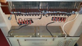
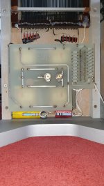
Joseph Audio has a patent on this crossover.
Joseph Audio

I haven't done a patent search but I did find an
explantion on how it works on the madisound forum.

snip.....
---------------------------------------------------------------------------------
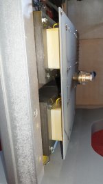
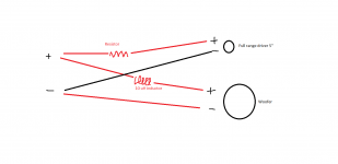
It works using the mutual inductance of windings inside a transformer.

Picture a transformer, with one primary winding, two secondary windings, the turns ratio being 1:1:1.

Connect the amp to the primary winding. Connect a driver one of the secondary windings. Now connect
the other secondary winding to the driver, except inverted and with a capacitor in series.

At low freqs, the cap disconnects the second coil and the output is largely unaffected.

At high freqs, the cap provides an AC short, which then opposes the formation of the mutual inductance
which would be necessary to induce current in either secondary winding. Output current drops toward zero
at high freqs because the mutual inductance between the primary and secondary drop toward zero at the
affected freqs.

The reflected impedance will begin to increase as the capacitor starts to provide the short. The amp
side sees the resulting cancellation of the mutual inductance as an open circuit on the secondary.
Also as the capacitor provides the short, the driver starts to see only the paralled DCR of the two
windings (and the cap) as the magnetic field necessary to create the inductance can't form (enough) a
round the closely coupled bifillar windings when one is inverted.
--------------------------------------------------------------------------

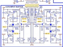
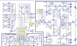
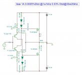
So... the question is.. is it possible to make an active crossover using this "patent" idea using a transfomer and capacitor and an op-amp to get a 120db/octave crossover ?

Sounds too simple to be true - lol

hmmm....

Why drivers sound differently?

I have played some with sb17 drivers, pp and paper and alu and satori and s-s’s, why do they all sound very differently even with matched freq responses and at low to moderat sound levels. some sounds upfront, some sounds layed back, some sounds big and round, some sounds pointy and edgy, why is that? Is the the cone material, is it the cone shape, or the small freq response differencies because i can not get a response that is 100% identical?

How do the sound of negative-wiring speaker?

I’m curious about the sound when I swapped speaker cable, between positive and negative, at speaker terminal. At first, I believed the sound would be the same whatever wired conventionally or reversed polarity. After trial, however, I can hear the different of sound! Could anyone please confirm me that the wiring polarity, at terminal, is matter? Also, I used to see some speaker’s schematics, not sure if they were vintage AR speakers, were put the passive network components on negative line. It would be very helpful if anyone has a microphone setup for doing a frequency swap, please assist to measure the response and phase for both cases. Thanks in advance.

4 Input SE Select, Volume, Mute, Remote

This project is a paired down board of another thread that has a 6 input fully balanced Digital Volume control on one large board, you can find that thread for an explanation of how this set of boards work. This project has 4 Input selection Single Ended, with Digital Volume (256 step), Mute, and an infrared remote control which is the same as the previous one, all on separate smaller boards.


Attached to this post is the Schematics for:
The Digital Board - 6" x 4"
The Analog Board - 6.5" x 3"
The Display Board - 6" x 2.75"
The Power Supply - 4" x 2.75"
The Remote Board - 2.65" x 1.5"


Next Post I will post the Bill of Material.
After that the Gerbers will follow.

Attachments

How are the channels "stored"digitaly?

Hello

it's probably a super simple answer and me over thinking, but everywhere i read about how DAC's work they show it in mono only and i have had a hard time to find any information how each channel is stored in the digital bits at all everything is just mono and basics.

is it so simple that each bit is stored like L,R,L,R in the signal?
or some other way.
do anyone know where i can read more about it since i don't know what to look for.

/F
Projects by fanatics, for fanatics
Get answers and advice for everyone wanting to learn the art of audio.
Join the Community
507,635
Members
7,881,643
Messages

Filter

Forum Statistics

Threads
405,927
Messages
7,881,643
Members
507,635
Latest member
tom.mccann