hi , have been trying to learn to make my own smps for audio, i went with interleaved pfc and llc resonant converter. please dont recomend to make linear psu as i want to learn.
issue is i cant find any store bought 500+W capable transformers at 150KHz.
is it practice to buy just cores and wind my own? if so what cores, where to buy litz wire?
i need 500W+, 60-190KHz, Primary/secondary ratio from 3.6-4 bias 13, inductance ratio 16, magnetizing inductance at around 90uH, output around 10 amps 50 volts, also 5 amps 50volts could be nice so i can paralell/series as needed and use similar design.
my maths is bit rusty so mostly used xls design calculator from ti chip to get specs mentioned, so i could be very wrong somewhere. thank you for any help.
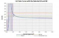
also attached is ss from calculated llc gain curve that i dont know how to interpret but think that it wont work over 60-70kHz.
Attachments
havent found nothing over 250w from wurth coilcraft and multiple sites like digikey mouser etc, could someone point me in direction where to buy cores?
Distrelec.nl has a decent collection of potcores and Epcos RM cores. I haven't a clue if any of them are suitable for your application, though.
With WE-760895651 tuned to 50kHz resonant frequency I achieved 300W continuous power output. With self wound xformers 400W continuous output power using an ETD39 core was my limit after a series of iterations. I would strongly recommend starting with these readyly built xformers for a novice who does not know much about cores, litz wires etc.
thanks everyone, have managed to find awesome core(https://www.we-online.com/catalog/datasheet/070-5724.pdf) that should be good for my application, also managed to get sample core only from wurth representative altough i doubt they will wind 10 pcs so i think i will have to wind those by hand, do anyone know where to get good high current litz wire?
Hi Toni,
For ordinary net-transformers (50Hz/60Hz - 115Vac/230Vac) there are few design parameters.
For SMPS transformers, there are considerably more design parameters including operation mode and frequency such that it is difficult to find standard transformers. Therefore as you have already concluded, SMPS transformers are most often custom-made eventually by yourself.
This is one reason why we tell optimistic new DIYers who wants to make their own SMPS that it is not that simple. Sometimes they seem skeptical about our advice.
The forces on the windings can be considerable with high currents, have you foreseen to keep the windings in place with epoxy or polyurethane?
thanks everyone, have managed to find awesome core(https://www.we-online.com/catalog/datasheet/070-5724.pdf) that should be good for my application, also managed to get sample core only from wurth representative altough i doubt they will wind 10 pcs so i think i will have to wind those by hand, do anyone know where to get good high current litz wire?
Litz is stranded and stranded is multiple conductors with a twist so you can roll your own. I've never built anything but my local supplier would be...
wires.co.uk : Stranded Enamelled Copper Wire
Not sure if they would post to Croatia but don't see why not. Not sure if the prices would make your eyes water but if you ignore the silly monster thin stuff at the top of the page you get down to £25/0.5Kg for n x 0.2mm
LLC is a dark art. I note that you have been having a poke around the TI web site. Last time I played 'air guitar' I ended up looking at...
https://www.onsemi.com/pub/Collateral/AND8460-D.PDF
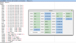
and wrote a simple program to do the sums. I really have no recollection as to what the heck I was thinking about but the resulting numbers appear to match the application note. It's written in FreePascal under Lazarus...
Lazarus Homepage
Lazarus
I'm using Linux but it is available cross platform and I'm sure what I wrote will be happy to compile under Windows if you want a play. Green is input numbers. Blue is calculated outputs.
You might also want to play with my roundwire calculator. That's done under Delphi(4). Hopefully still works under Windows. Works out AC/DC wire resistances based on Dowells curves.
In both cases I might have to hold your hand a bit so you can get some idea as to how my warped mind was thinking. There is no rational thinking just a set of processes I would run through to arrive at an end result.
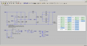
As I say unlike yourself I don't build things but if I were to approach something like this I would be setting up a model in LTSpice and extracting relevant, hopefully meaningful, numbers from the simulations before actually producing a 'real' thing. I would hope to end up with a full, ideal, convertor model that demonstrates regulation and protection loops
I'd be happy to play if you want.
Attachments
Just for the giggles here we go. 500W according to your design suggestion but I set 5.5 as the 'ratio'. Apparently, making things up as I go along, that one affects peak/average things elsewhere and things get out of hand if you ask to much.
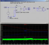
Likely completely bricks itself on start up but when things have settled down peak voltage across Cres is about 320V and RMS current through Cres is about 2.8A so it appears to agree with the application note.
...
Likely completely bricks itself on start up but when things have settled down peak voltage across Cres is about 320V and RMS current through Cres is about 2.8A so it appears to agree with the application note.
...
Attachments
Christophe Basso has chapters of two books and several application notes (from OnSemi) devoted to SMPS transformers -- you can find excerpts on the web.
As the magnetics in each SMPSU are the hearth of them, I really doubt that you can find an "off the shelf" transformer (Perhaps an inductor can) that performs pretty fine in you design/project. Usually they are done as a specialty for each one of them.
Also Bob Mamanno and Lloyd Dixon from TI. Very interesting series of articles, free.Christophe Basso has chapters of two books and several application notes (from OnSemi) devoted to SMPS transformers -- you can find excerpts on the web.
If you do not know where to get cores and litz wire, you should go for a ready xformer from wuerth. Period.
With an LLC converter there are other problems to be dealt with besides the transformer. It will take you some steep learning curve and a handful of burnt semiconductors before reaching useful results. I have been there, done that - and after taming this beast I love LLC converters.😉
With an LLC converter there are other problems to be dealt with besides the transformer. It will take you some steep learning curve and a handful of burnt semiconductors before reaching useful results. I have been there, done that - and after taming this beast I love LLC converters.😉
Just for the giggles here we go. 500W according to your design suggestion but I set 5.5 as the 'ratio'. Apparently, making things up as I go along, that one affects peak/average things elsewhere and things get out of hand if you ask to much.
Likely completely bricks itself on start up but when things have settled down peak voltage across Cres is about 320V and RMS current through Cres is about 2.8A so it appears to agree with the application note.
...
That is a lot of help, thank You and everyone very much...
now the more i read the more am aware to have bitten a lot more than can chew. ok that is where the fun is. 😀 back to start and retry.
so it does blow up on startup, was thinking that since controller chips datasheet says soft start with no hard switching that this kind of problems will be non existent? UCC256304 is used controller chip. was thinking of trying to simulate but that is way too hard stuff, more easy to redo pcb few times 😀
also pcb will be huge 25x15cm, if not more when finished. im afraid it will work but will not be efficient.
Blow up on power on is an issue here as the empty output caps are a short circuit at start up. The soft start is the common solution. It works, if the loading capacitance is restricted according to the softstart timing. I consider this beeing a workaround for the missing primary peak current limit. My recommandation is "forget the softstart, with a cycle-by-cycle peak current limit you do not need it". The solution has been described by Bo Yang: "Topology Investigation for Front End DC/DC Power Conversion for Distributed Power System". It boils down to 2 Diodes clamping the primary resonant tank to the supply rails.
There are more questions to be answered:
What is your average/peak power requirement?
Do you really need a regulated output?
I recommend an unregulated LLC with a fixed frequency tuned to primary series resonant frequency. The advantages are
-deadly simple
-no regulation effects, absolutely stable at load transients
-lowest output impedance
-highest efficiency
-ZVS available from 0~100% load, i.e. no switching loss
The fotograph shows my working 400W LLC prototype with hand wound xformer on 100x100mm pcb
Attachments
Last edited:
Another issue is secondary rectification. With dc currents above 1~2 amps the diodes need heat sinks. And these quickly grow with increasing current demand. For a compact design the synchronous rectifier is your choice. Besides the improved efficiency voltage stability of unregulated LLC is superior, i.e. there is no voltage overshoot at light load you will observe with diodes.
The unregulated LLC may be considered the direct replacement for the conventional unregulated toroidal mains transformer supply with similar 100/120Hz output ripple but superior output impedance yielding good stability of DC output. Here the bulk capacitor that determines output ripple resides on the primary side, i.e. there is no point using extra high capacitances on the secondary side.
The unregulated LLC may be considered the direct replacement for the conventional unregulated toroidal mains transformer supply with similar 100/120Hz output ripple but superior output impedance yielding good stability of DC output. Here the bulk capacitor that determines output ripple resides on the primary side, i.e. there is no point using extra high capacitances on the secondary side.
Last edited:
That is a lot of help, thank You and everyone very much...
now the more i read the more am aware to have bitten a lot more than can chew. ok that is where the fun is. 😀 back to start and retry.
so it does blow up on startup, was thinking that since controller chips datasheet says soft start with no hard switching that this kind of problems will be non existent? UCC256304 is used controller chip. was thinking of trying to simulate but that is way too hard stuff, more easy to redo pcb few times 😀
also pcb will be huge 25x15cm, if not more when finished. im afraid it will work but will not be efficient.
Nooooooo.
That's the model. Notice that I have set the Modulator to run from 90KHz to 150KHz. This is the design operating range for regulation. Whilst I ramped CON down from 1V to 0.5V, 150KHz to 120KHz in the actual design Fmax will likely be higher... 300KHz?
It's not there to put you off. It's there to play with and blow up on your computer. When it stops doing that you have a bit more confidence in the design.
Attachments
• FastExit fromBurstMode• ImprovedCapacitiveRegionAvoidanceScheme
is this two things help with startup?
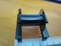
bobbin from wurth arrived yesterday, now to calculate how fat wire and stuff, this is prooving to be whole rack full of cans of worms, but it is fun..
if You could forgive me i dont understand half of stuff you say as i am not native english speaker, and am new to this stuff. thanks anyway.
Attachments
Burst mode is used when the load is light. The supply kind of hiccups to just keep things topped up at the output. It sounds good to come out of or wake up from it fast to cope with a dynamic output. They really should have put some more thought into Improved Capacitative Region Avoidance Protection. ICRAP. The second will help with start up and elsewhere.
I'm more or less down at the bottom of this curve with you. Someone shout if I get this completely wrong however this is the way I would proceed.
For your first go it's probably best not to overthink the transformer. Consider using an external inductor as the resonant part. Others have mentioned names for reference material but the only one that floats to the top of my head is one by Dixon...
http://www.ti.com/lit/ml/slup105/slup105.pdf
Perhaps the others can come up with other examples.
Assuming you use an external inductor then when you wind the transformer you want to associate any leakage with the primary and based on what Dixon says that means you would flat wind the secondary closest to the core, first, and then place the primary on top of it, second. Measure the resulting leakage inductance if you can, shorted secondary, and take that away from your added inductor value.
If you do want to incorporate the resonant inductance as leakage then I would be inclined to uses Dixons suggestion of placing a gap between primary and secondary. At least the application note gives you an estimate of the value you might expect. Unfortunately that robs you of primary winding area that might have been used for copper.
AFAIK the more esoteric methods involve placing the core gap off centre so it and its energy is preferentially coupled to the primary. That's conceptually herder to explain and characterise. You also have a problem that someone will happily sell you core halves with the gap in the middle of the centre leg and that leaves you less room for manouver.
As a first guess the control method control IC should not impact the operating waveforms for the final circuit. As such you can use the simple model to give you an idea of the primary and secondary winding currents. Run the model, plot the currents and run an FFT on them. Fingers crossed you should find they are concentrated at one frequency.
There are software packages available that might do the work for you. I haven't tried them, won't work under Wine but...
Ferrite | TDK Electronics - TDK Europe
Otherwise...
https://www.tdk-electronics.tdk.com...0b4d8aac6ea08cc21352bf2d8/pdf-application.pdf
It looks like you have an ETD39 bobbin. Page 31 give the thermal resistance of a fully wound core as being 16C/W assuming convection cooling. Pick an ambient of 40C and allow a maximum operating temperature of 100C. that gives you a total allowable dissipation of about 3.75W. Assign half to the core and half to the windings or 1.9W each. Ideally that will partition as 0.95W primary and 0.95W secondary.
You will have to look at the properties for the material you are using for the core and the core itself.
https://www.tdk-electronics.tdk.com/download/528882/71e02c7b9384de1331b3f625ce4b2123/pdf-n87.pdf
https://www.tdk-electronics.tdk.com/inf/80/db/fer/etd_39_20_13.pdf
Ve is 11500E-9 m^3 and you've allowed 1.9W so your Pv is 165kW. The relative core losses versus frequency graph in the materials properties, bottom of page 5), suggests you can run to 100mT @ 120KHz for about 165kW. The graph is for peak flux, single quadrant operation. You can double that, any convertor, as long as you do not hit the saturation limit for the material. So your number is 200mT.
Plug that in the calculator to find your minimum primary turns. Take the square root of the ratio of Lmag and Lsec to work out the secondary turns.
For the bobbin take off 3mm either side of your bobbin for insulation/isolation and 6mil, three layers of tape, from the height for insulation and divide what's left in area terms by two. You will be operating the primary and secondary at the same current densities so they will be occupying the same area. Multiply that by 0.7 because you will be using round wire or round rope. NPmin was given by the calculator so divide that into the last one and that will give you the approximate area of your conductor.
Then iterate through with that roundwire calculator to find the best compromise for Rac/Rdc. The calculator will factor in how much insulation robs you of area, assume heavy insulation even if you are using litz. Apparently you target an Rac/Rdc of about 1.4 as a point of not much improvement. Once you are about there check the I squared losses for the windings based on the numbers provided by the model.
Then you iterate again... and again over power and nominal operating frequency. If it does not want to play, very likely, then your core is too small. If it looks too easy your core is too big. If it is just about right then it might work.
- Home
- Amplifiers
- Power Supplies
- Where are high power smps transformers
