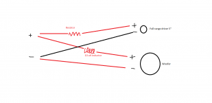
So, the high frequency driver is really just a full range driver, running without a filter. So, just attenuation.
A 6db per octave filter for the low frequency driver.
My question is this.....While adding attenuation, increasing the resistance of the resistor inline with the full range driver, does there come a point where there is enough resistance that the response starts to suffer? Or can I simply add resistance until it sounds right? I mean, what if there was 20ohms? 50ohms? 100ohms? 500ohms? Does the reduction in output of the full range driver remain linear or do irregularities begin to show as I increase the value of the resistor?
Attachments
More than a few ohms in series will be very wasteful of amplifier power, and signify that
the driver choice was not optimum. With an even larger series resistance, the frequency
response curve will start to have the shape of the driver's impedance curve, not good.
There's also a very low damping factor with larger values.
the driver choice was not optimum. With an even larger series resistance, the frequency
response curve will start to have the shape of the driver's impedance curve, not good.
There's also a very low damping factor with larger values.
Last edited:
So the full range / high frequency driver will see very little power because so much power was dropped at the resistor? But this will in no way effect the woofer, right?
And what about the response of the high frequency driver? Does it remain the same, just with a drop in output, or does the response change with the output as resistance goes up?
I am guessing that the woofer does not get effected and the drop in output of the full range driver does not come with a change in response. But I seek further input on the matter.
It won't affect the woofer, they are in parallel with a voltage source.
The response will change as the series resistor increases. It will resemble the shape
of the driver's impedance curve more and more with higher resistance, due to the
voltage divider action.
The response will change as the series resistor increases. It will resemble the shape
of the driver's impedance curve more and more with higher resistance, due to the
voltage divider action.
Last edited:
So, would it be more logical to do an lpad style fixed resistor set-up? One series resistor, one parallel resistor?
Yes, this will reduce the issue but not eliminate it.
The issue doesn't have to be a problem. Nelson Pass has done a study on this effect with full range drivers and found fortunate interactions. This wasn't, however when a crossover was involved.
If you plan to measure then you can easily compensate either way.
The issue doesn't have to be a problem. Nelson Pass has done a study on this effect with full range drivers and found fortunate interactions. This wasn't, however when a crossover was involved.
If you plan to measure then you can easily compensate either way.
You mean Pass did a study on placing series resistors on full range drivers and found the results to be positive?
As a general rule, how much resistance does it take before the results become problematic?
As a general rule, how much resistance does it take before the results become problematic?
That's right. I'll attach the *.pdf from PassDiy. It discusses the reasons and includes plenty of examples. (it is a pdf that has been zip(ped) so I could upload it)
Don't mistake that when he says current source amp, this also includes typical amps with a series resistance included.
Don't mistake that when he says current source amp, this also includes typical amps with a series resistance included.
Attachments
That's right. I'll attach the *.pdf from PassDiy. It discusses the reasons and includes plenty of examples. (it is a pdf that has been zip(ped) so I could upload it)
Don't mistake that when he says current source amp, this also includes typical amps with a series resistance included.
Thanks for the link.
Been looking through it.
I don't completely follow the "conclusion"....he says...."Placing R0 in series with the output of a powerful voltage-source amplifier instead of in parallel with a current source will give similar results. If R0 is 47 ohms or higher, you are going to want a big amp....".
Does this mean putting R0 in series and leaving everything else in the network intact, or replacing the network with a series resistor?
As described, it is on its own. In your first post you suggested you weren't planning to use anything but resistance. However if you change your mind I think we could work something out.
Edit: I think I misunderstood you there. You can put the resistor in series with your full-range driver, and still have the woofer and woofer network in parallel with all of that.
Edit: I think I misunderstood you there. You can put the resistor in series with your full-range driver, and still have the woofer and woofer network in parallel with all of that.
Last edited:
So, the high frequency driver is really just a full range driver, running without a filter. So, just attenuation.
A 6db per octave filter for the low frequency driver.
My question is this.....While adding attenuation, increasing the resistance of the resistor inline with the full range driver, does there come a point where there is enough resistance that the response starts to suffer? Or can I simply add resistance until it sounds right? I mean, what if there was 20ohms? 50ohms? 100ohms? 500ohms? Does the reduction in output of the full range driver remain linear or do irregularities begin to show as I increase the value of the resistor?
Rather than reinventing something that has been done before, it might be good to look at some existing designs:
Speaker Design Works
The idea is the woofer does the bass, and the fullranger takes over at a higher frequency. This saves the fullranger from big movement or excursion, which tends to distortion.
In practise, this means some sort of capacitor filter to the fullranger. Which is what AllenB is talking about.
You can model this:
Software | Visaton
FAST – Boxsim Projektdatenbank
Visaton do quite a few fullrangers, and they won't work much differently from yours.
- Home
- Loudspeakers
- Multi-Way
- Padding a high frequency driver in a passive crossover