High performance OPA1602 + TPA6120A2 Composite Headphone Amplifier

Hello guys,
About half a year ago I decided to design my own high performance headphone amplifier. The idea came more from some kind of engineering challenge rather than serious need - my O2 was probably more than enough.
My designs considerations were pretty simple:

  • Challenge myself and check what lowest distortion can I archive
  • Decent power with ability to drive almost any headphones
  • Near zero output impedance
  • Safe for headphones, no DC at output and stability in any conditions
  • Relatively cheap and easy to build - no unobtainable, expensive or exotic parts
After a bit of reading, tinkering and simulations I settled with composite amplifier architecture. I've considered lot of solutions including discrete buffer, LME49600, numerous models of opamps, ADSL line drivers. Every solution had its pros and cons like price, stability, output impedance, DC characteristics, output power, minimum load resistance, complexity, power dissipation limit, temperature and so on.

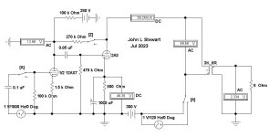
Finally I decided to nest already very good TPA6120A2 inside feedback loop of another operational amplifier. At this time I'm using OPA1602 but want to experiment with something else like OPA1652 or OPA1656. Especially the last one seems promising but first I need better test equipment to analyze such small distortion levels.
TPA6120A2 is almost perfect candidate apart from one thing - stability. It is current feedback operational amplifier and its stability is not so easy to tame. High attention must be paid to minimize stray capacitances at PCB.

Apart from that TI recommends at least 10 ohms of series output resistance. But this means rather high output impedance. I tried to address this issue in two ways - complex feedback, post output resistor or output inductor.

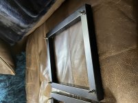
At this time I'm using ~300nH air core inductor at output. TPA6120A2 seems happy with it and output impedance is very low, about 10 miliohms. There is downside tho. Such inductors are hard to get off the shelf so I had to hand wound them. Inductors with other that air cores probably would introduce high distortions.

But there is another way. PCB can be configured to take feedback post resistor/inductor. This configuration is not so popular way of isolating capacitive load from amplifier while maintaining low output impedance. I haven't tried it yet but possibility of omitting inductor is very promising.

For power supply good, old LM317 and LM337 regulators are used with half wave rectifier. Board can be powered by AC-AC wall wart or transformer. Those wall warts are cheap and easy to use as there is no contact with potentially dangerous mains wiring.

Instead of using more common voltage divider to set output voltage I decided to use zener diodes. Dynamic resistance of zener diode is lower than required resistor which should result in lower output noise. By default 13V zeners yields about +/- 14.5V at output with less than 10mV difference between negative and positive rails.
Cadj capacitors are of course present. There are two LEDs at both rails. Besides being indicators they run at relatively high current, providing constant load to regulators which keeps low output impedance of power supply.

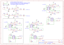
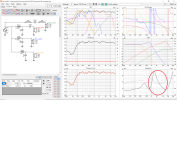
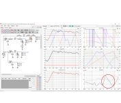
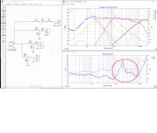
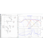
Whole PCB was designed in free and open source software - KiCad. Simulations were done in LTspice.

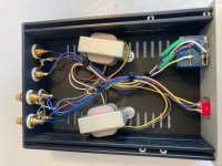
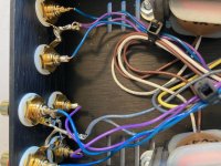
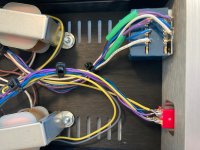
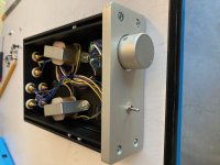
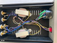
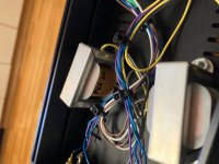
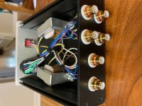
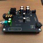
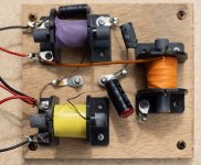
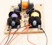
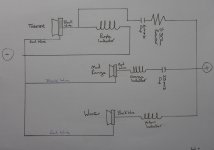
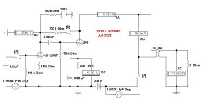
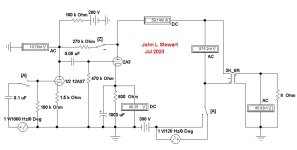
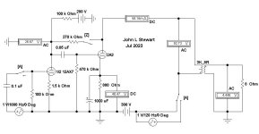
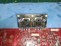
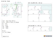
3D render, real photo taken before mounting my ugly hand wound inductors and schematics could be found in attachment.

What are my plans for future?

  • Learn CAD software to design enclosure and order it at CNC workshop
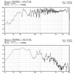
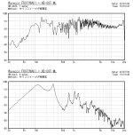
  • Acquire/build equipment allowing me to measure true performance of amplifier (aiming <-130 dB THD)
  • Adding micro controller (probably STM32) used for monitoring amplifier - temperatures, DC offset, failure, relay control and etc.
  • Maybe bigger version with XLR input, preamp output, switchable gain and Alps RK27 volume control?

Attachments

Passive preamp - Electra-Print PVA-2n build

I built Electra-Print's passive preamp using a pair of their PVA-2n audio transformers, following their circuit design, but with two switchable inputs and no subwoofer output:

Electra-Print.com PVA Passive Audio Pre-Amplifier
You Can DIY! Passive Preamp: Transformer Implemented | audioXpress

I used a Galaxy 1U 124mm x 170mm Alu case from diyaudiostore.com with customized drill holes for an ALPS 10k pot and a DPDT on-on toggle switch on the front panel, and three sets of RCA jacks on the back panel. I drilled out a few of the vents on the bottom panel to accommodate mounting screws for the trafos.

With the PVA-2n based passive preamp replacing a Schiit SYS passive preamp (10k audio taper pot with switchable inputs), my system sounds amazing. My perception is that digital sources (a Sony CDP-302 and a RaspberryPi with a AD1868 DAC HAT card) sound much cleaner, with more instrument detail and better levels (frequency response). Listening fatigue I experienced with the CDP-302 completely disappeared last night, and albums with challenging levels to my ears, like U2's The Joshua Tree, suddenly sound way better balanced. I much prefer the sound of this preamp to my Korg NuTube B1 as well.

The only real downside was sourcing parts from multiple vendors and the cost of the customized case. Being my first build completely from scratch, I'm satisfied with how it turned out. Hope you enjoy the pictures.

Attachments

  • IMG_5632.jpg
    IMG_5632.jpg
    734 KB · Views: 570
  • IMG_5633.jpg
    IMG_5633.jpg
    752.9 KB · Views: 465
  • IMG_5634.jpg
    IMG_5634.jpg
    631 KB · Views: 418
  • IMG_5635.jpg
    IMG_5635.jpg
    508.6 KB · Views: 423
  • IMG_5636.jpg
    IMG_5636.jpg
    808.3 KB · Views: 465
  • IMG_5639.jpg
    IMG_5639.jpg
    534.6 KB · Views: 252
  • IMG_5640.jpg
    IMG_5640.jpg
    668.3 KB · Views: 241
  • IMG_5641.jpg
    IMG_5641.jpg
    707.2 KB · Views: 275
  • IMG_5643.jpg
    IMG_5643.jpg
    670.6 KB · Views: 331

For Sale FS: Two Focal 6K412L Bass-Midrange drivers NOS (USA)

I have two unused new / old stock Focal 6K412L bass-midrange drivers. Bought for a project long ago and since abandoned.
These are 165mm (6.5 in) drivers with gorgeous yellow kevlar cones in cast frames. Still in the original boxes. See pics below.
Nice for 2 way or 3 way with subwoofer.

$25 each or $40 for the pair + shipping from Chicago, IL, USA

Weight in original boxes is 60 oz = 3.5 lbs = 1.7 kg each.
Weight for two in a shipping box with extra padding is expected to be about 9 lbs.

One speaker will fit in a USPS Medium Flat Rate Priority Box and cost $17.10 to ship anywhere in the continental US. Unfortunately two speakers will not fit into the large flat rate box so using USPS Priority Mail would be two boxes.

Price with USPS Ground Advantage for both speakers together is expected to be about $24.40 or less within the continental US.
Will take Paypal, Venmo, or Zelle.

Attachments

  • 6k412l.jpg
    6k412l.jpg
    597.4 KB · Views: 175
  • PXL_20230802_161619750.jpg
    PXL_20230802_161619750.jpg
    81 KB · Views: 142
  • PXL_20230802_161718605.jpg
    PXL_20230802_161718605.jpg
    124.8 KB · Views: 151
  • PXL_20230802_161736681.jpg
    PXL_20230802_161736681.jpg
    98.9 KB · Views: 111
  • PXL_20230802_161606546.jpg
    PXL_20230802_161606546.jpg
    100.4 KB · Views: 111
  • PXL_20230802_161713081.jpg
    PXL_20230802_161713081.jpg
    115.3 KB · Views: 133

Teac A-4070 refurbish complete

I just finished refurbishing this Teac A-4070 (plays forward and reverse). I have refurbed and built from scratch quite a bit of gear. This was my most difficult project yet. I bought it in March for $20 not working, power up only. I ended up replacing all of the electrolytic caps, some of the film caps, some transistors and all 4 heads.
I used NOS Nortronics for the playback heads and was very lucking in finding NOS Teac record/erase heads. It seemed like every time I fixed something another problem popped up. It had hot chassis issues that went away when I removed the extra wiring etc. associated with using different voltages. I will never be used outside of the US now anyway. It cleaned up nicely and more importantly sounds fantastic now hooked up in my main system.
complete teac.jpg
  • Like
Reactions: alighiszem

For Sale Mechanics special ACP+, 2 ACAs plus 2 Galaxy 1Us

So my stash was invaded by a 4 y/o 3' tall white male perp. Managed to drop one of the ACA's and bent the back panel. Fins and front panel perfect. I purchased another back panel with the intentions of making it right but have lost interest. Both ACA's are V1.18 and were working fine before the ransacking but I believe the bent one lost a wire solder to the back panel. To be safe I would assume that both need a good going over as I have not tested either since putting them on the shelf a few months ago.

$350 plus 25 shipping includes both ACA's with power supplies and extra back cover and the SMPS filters. You might have to do some work but you're in at less than half price from the new kits. I will post some pics shortly but if you want specific pics PM me. These are all silver faced units.

The ACP+ kit is SOLD...should power up but in the mayhem the ground plane bolts/nuts, power supply and volume knob were lost. I'm still looking for those items but the kid is pleading the fifth. It does have the ground plane. I also have 3 complete SMPS filters that go with it.

I also have two Galaxy 1U enclosures new in the box. SOLD One 230mm x 170mm with 10mm front and one 230mm x 170mm with 10mm silver front. $50 each shipped.

Pics below.

I‘m wasting my time in one of the most beautiful places in Europe

So here I am in Torino, Piemont, for a one-day trip with the family. Got there at 10 in the morning, and until now, I have seen h&m, COS, Zara (and another one not worth being mentione), and had a bowl of something inspired by japanese kitchen.
According to maps, I haven’t moved fuether than 4 minutes from the starting point.
So much for holidays.

For Sale Holy grail Russian NOS 6N30P-DR/6Н30П-ДР

I have several of these old stock 6N30P-DR tubes, made early 1980s and in new, unused condition. I’m looking for $100 per tube. Payment per USPS money order and shipping is on you from Central Illinois, 61821.

Attachments

  • F6B27E5B-55B6-4804-A5D0-7E5A0F0CECA7.jpeg
    F6B27E5B-55B6-4804-A5D0-7E5A0F0CECA7.jpeg
    552.1 KB · Views: 161
  • 331D30FA-4D1A-4828-B5F0-AF1BC5D18624.jpeg
    331D30FA-4D1A-4828-B5F0-AF1BC5D18624.jpeg
    592.5 KB · Views: 148
  • image.jpg
    image.jpg
    401.4 KB · Views: 168

Audio difference maker - use with music files

I have two editions of Solti's Mahler 2nd Symphony


Folder.jpg


Folder.jpg


I would like to find out whether there two editions are identical (whether the Mangora Classical is just a license from DECCA).
I have downloaded @bwaslo 's audio difference maker, but I found no way to use it not with a microphone, but with two existing audio files. Can anyone point me in the right directions how to do this?
Thanks a lot

F5X -- the EUVL Approach - The Build Thread

This thread will document build details for EUVL's F5X amplifier. The main thread is here: F5X -- the EUVL Approach

I'll start off the thread with the official BOM and schematics, Circuit board assembly, amplifier initial biasing and bring up. There will be some related articles thrown to help as well. Measurements will be posted as soon as I have time to compile them and there will be information about final wiring and the amplifier case along the way.

Thank you for your patience and feel free to post assembly related comments or questions here. Let's keep this thread focused on assembly or similar issues and maintain other discussions on the main thread.

Enjoy,
Dave

Hello from Oregon

Howdy to anyone reading this, my names dan and I'm obviously new here. I've been lurking around reading what others have written and trying to learn more about diy audio. I'm currently using a xls1502 class d crown amp and a parasound halo p3 pre. I've been looking for new gear and almost pulled the trigger on a fw f6 the other day, but I've decided I think I'd like to build my own amp, pre and phono. I haven't done any sort of electronics building since I was in high school. I've done some soldering on rc cars more recently, but I definitely could improve my skills. I've been looking at the aca, elekit and bottlehead stuff. I'd like to have my first introduction into audio equipment building be kits to take a little bit of the guess work out of sourcing parts and just general lack of knowledge. I appreciate any advice. Thank you. Glad to be here and I hope everyone's having a good day/night.

For Sale unique DIY projects sold as is and for parts even though all work fine

Fre items that ill include with every purchase listed in the following posts. for my feedback on ebay, reddit, audiokarma and audiocircle message me but if you are not ok with fnf dont message me.


1 - Integrated amplifier DIY project (AC line filter + Soekris R2R DAC with its own lienar power supply + volume control in digital domain + TI 3255EVM with its own switching power supply)
all in one box $299 for everything in the pics + $34 shipping conus (you will not beleive the weight) total $333 with zelle or paypal fnf or venmo. there will be no guarantees for anything sold for parts. Login to view embedded media
The red signal wires are neotech super expensive wire. I built this some years ago and tested everything except the line filter. so I know its all good but i am selling for a fraction of the cost of the parts so there will be no guarantee or after sales service. I'll try my best to secure everything for shipping but there will be no expressed or implied guarantee. The super binding posts are also very nice. i was very impressed by them. The holes in the back plate are all hand drilled and messy. not pretty. The gauges in the front work beautifully. this is a video of an earlier version before I added the DAC but it shows the gauges Login to view embedded media


2 - CROWN 1502 barely used $275 with CONUS shipping on me fnf Login to view embedded media
3 - this stuff all together $100 + $30 shipping conus (super heavy) = $118 fnf Login to view embedded media that's the DIYaudio power supply built with the most expensive parts and tested.
i wont list the rest. just look at pictures.


4 - akitika phono pre amp. here is info: https://www.akitika.com/PhonoPreamp.html

built with highest level of care. all wires and components are fancy. here are pictures and proof of ownership: Login to view embedded media price: $199 shipped fnf

Portable cassette player recording mystery

I am trying to use a portable cassette player to play tapes and record them on my pc. I can play tapes on the tape player and listen to them on headphones plugged directly into it with no problem. When I plug the player into my line-in on my pc, all I can record or hear on my pc is spurts of low distortion every once in a while. I can only get the sound if I turn the levels all the way up. So I thought the problem was with my pc so I used an old phone with a headphone jack and plugged it into the same line-in. I was able to hear and record from the phone no problem. So why do I have this problem with the tape player with my pc?

Ohm Acoustics is "For Sale"

Asking price is $875,000.

https://www.ecoustics.com/news/ohm-acoustics-for-sale/

https://www.bizquest.com/business-for-sale/custom-speaker-manufacturer-brooklyn-new-york/BW2084589/

Current owners wish to retire.

I think it's a lot of money, considering that their factory is a rented premises, and apart from the trademark, as far as I know there is no protectable Intellectual Property.

Somebody could buy a pair of the big Ohm speakers and send them to China and get them cloned.

Anyway, this is a tough time to sell any business that is not recession-proof. The Credit Rating of the United States of America just got lowered, for Pete's sake!

john

Fixing ban from vinyl engine?

Hi,

I got banned today from vinyl engine, and got this message as I was trying to log in: permanently banned because of use of VPN proxy servers...

I don’t have a vpn active, nor use a proxy server that I know of. I kept having problems on iPad where I would log in, and it wouldn’t allow me to stay logged in long enough to look at any manual. Had trouble at work both on my desktop computer and my iPhone when the phone was on WiFi. Phone on cellular data allowed me to download. Then at home, using the WiFi in my house, I kept getting booted on the iPad. The told my account was permanently banned.

Anyone else having similar problems? Anyone have any suggestions for how to fix this? I’d love to be able to get back on there. Good people and information.

Headphone distribution amp with VU display

I'm a musician hobbyist and class myself as a beginner. I don't really know what I'm doing... would somebody be kind enough to take a look at my plans?

I'm trying to design a headphone amplifier that will take an audio signal from a laptop (line level, but quite low), and drive 3 sets of reasonable quality headphones at good volume. I also want to add a VU display, which I intend to calibrate to the laptop audio software. The idea is 3 people working on an audio project can hear what they're doing, and the VU is mostly for fun.

This is what I've come up with for the audio side of things. I've not designed the VU display etc. yet.

Does it make sense? Any obvious mistakes or improvements?

Attachments

  • Schematic_Sound Distribution Board_2023-08-03.png
    Schematic_Sound Distribution Board_2023-08-03.png
    129.1 KB · Views: 138

Mini Speaker using Wavecor FR084WA01 (3.5" Full-Range)

Wavecor FR084WA01 is recommended for its excellent sound quality and high cost performance.

Wavecor 3.5 inch - 01.jpg


Sound Quality Top 3 (3" - 3.5")
1st : TangBand W3-1878
2nd : MarkAudio MAOP5
3rd : Wavecor FR084WA01

Cost Paformance Top 3 (3" - 3.5")
1st : Wavecor FR084WA01
2nd : SPK Audio FR03E
3rd : MarkAudio CHN519

Login to view embedded media

Attachments

  • Wavecor 3.5 inch - 03.jpg
    Wavecor 3.5 inch - 03.jpg
    107.4 KB · Views: 199
  • Wavecor 3.5 inch - 04.jpg
    Wavecor 3.5 inch - 04.jpg
    44 KB · Views: 209
  • HB-07F-ML-01.jpg
    HB-07F-ML-01.jpg
    185.7 KB · Views: 211

Advice for replacement bipolar electrolytic capacitor 0.22uF to 1uF - Recapping Pioneer SA-606

Hello guys, in these days I was creating a BOM to replace all the electrolytic capacitors of the Pioneer SA-606.
Long story short, I've found this amp on the street abandoned, cleaned it, tested it, and I really liked the sound of it, using it as I am writing as my desk amp 😀

I created a BOM of components on Digikey, the problem is, I cannot find a replacement for the bipolar 0.22uF 35V capacitors (C31, C32), the minimum size for bipolar electrolytic capacitor it is 1uF 50V! Could I safely replace it with a bigger size?

I did the same time with the filter capacitors, went from 8000uf 50v to 10'000uf 50V because they were more common:

This is the schematic of the amplifier (taken from the service manual), I highlighted all the capacitors to replace, the C31, and C32 cap are marked in blue!

IMG_0943.PNG


This is the list of all the capacitors that I took note to replace:
C1,C2 2.2/50 YES
C9,C10,C45,C46 220/6 YES
C23,C24 2.2/50 (Non polarized NP) YES
C31,C32 0.22/35 (NP) (found alternative 1uF 50V bipolar)
C41,C42 22/10 YES
C53,C54,C55,C56 4.7/35 YES
C57,C58 10/16 YES
C62 220/25 YES
C63,C64,C65 100/25 YES
C67,C68 220/50 YES
C69 10/25 YES
C59,C70,C71,C80 10/50 YES
C72 33/25 YES
C73 33/50 YES
C75,C76 8000/50 YES (found alternative 10'000uF 50V)
C77,C78 470/6 YES
C81 22/16 YES

Probably is not needed always, just in the signal path, but I tried to only select capacitors for audio application.

This is the BOM from Digikey:
Digikey

I also needed to replace the lights of the vu-meters, so most likely I will go with something like that:
Ebay

Also, do you know a good contact cleaner available on Digikey? To add in the basket to not pay the shipping fees 🙂
(I need it for cleaning the switches and volume/balance pots)

What am I doing wrong? (300B HF Boost)

I’ve been working on my 300B amp and after some subjective listening tests, my main issue is the roll off on the top end… sure enough, it drops off after 10k… So after some experimentation I decided to “voice” it away by playing with the bypass scheme of the second stage… Seems to have flattened things out…. I lose some input sensitivity but it was very sensitive to begin with…

Now… this is where I pause and think
- There must be a reason i’ve never seen this implemented anywhere else that i’m aware of… what am i not considering?

- I feel like this isn’t addressing the main issue of “something something miller effect” it’s remedial… But the only “real” solutions seem to require unobtainium loctal tubes, interstage transformers that I don’t have space for, or some sort of mosfet follower that I don’t think I can easily implement into this topology…

- there might be something else in my circuit causing the rolloff

Here is my quickly drawn schematic… Missing is the details of the HT supply - it’s fairly conventional. What I did draw is the filament supply since once again, I did something I don’t see in other schematics and thus might be a factor in my HF rolloff behavior:

A0942B72-5CF4-445C-9BCA-68A80E6478AA.jpeg


Before (purple) and after (green) bypass tweak:
C642B059-2135-442F-B4D2-5BD4DD76BD6E.png


How does it sound? I don’t know… at this point I have “tunnel hearing” and don’t trust my ears anymore.

Any advice or comments would be appreciated! thanks!


Updated schematic:
415AF2CF-61FC-4EFD-8B1F-1F778C43900C.jpeg

Wharfdale Dovedale III Wiring help

Hi all
I am new to this forum, scratch that first time on anything like this so please go easy. I have renovated a pair of glendales recently recapping, veneering and new grill covers.
They do look quite different but more to my taste. Although not a member I found some great help reading some posts on this site hence me now joining.
I am not an electrician and do have to read things a few times till I understand and google the terminology quite a bit.

I have recently purchased a pair of Dovedale IIIs and am unsure if they are wired correctly. They only have the two speaker terminals on the back so I assume they are older ones.
I have seen a photo of the crossover on here but cant see which driver goes where. I will attach photos and a basic schematic of what appears to be happening in the cabinet.
I think that the woofer is wired the wrong way around but am happy to be put right thanks for any help.

Attachments

  • 1 Dovedale Front.jpg
    1 Dovedale Front.jpg
    279.5 KB · Views: 120
  • 2 Dovedale Rear.jpg
    2 Dovedale Rear.jpg
    603 KB · Views: 104
  • 3 Crossover.jpg
    3 Crossover.jpg
    407.7 KB · Views: 100
  • 4 Wiring.jpg
    4 Wiring.jpg
    418.5 KB · Views: 100
  • 5 Wrong Phase.jpg
    5 Wrong Phase.jpg
    213.9 KB · Views: 112
  • 6 Dovedale III Diag  I think this is wrong.jpg
    6 Dovedale III Diag I think this is wrong.jpg
    474.7 KB · Views: 127

Intermittent Pops in Stereo

Hi Friends,

I'm more active on AK than here as I'm very much a novice, but eager to learn.

I have posted about the issue described below at that other forum with lots of help and insight, but just seeing other options here. Some brief background:

  • My system: Nakamichi PA-7AII, CA7A, SL1700MK2, Bluesound Node 2i (into SMSL SU-8S).
  • The chief complaint is as the title suggests: I have intermittent pops through both channels on all inputs with volume at 0% or 20%.
  • I first noticed the issue after two short afternoon brownouts. The system was on, and the power cycled before I could switch it off. It was plugged directly into the wall.
  • No noticeable issues -- no smoke, no change in sound, so I assumed the system was totally fine. Then I heard the pops, like static discharging.
  • I have tried most troubleshooting tactics -- different outlets, different rooms; Amp/Preamp combos (more about this below)*, with or without a power conditioner (Furman PST-8).
  • The amp has been serviced, mostly bias adjustments (and a resistor in protection circuit that fried).
    • It was most recently by Jon Soderberg of Vintage Amp Repair (PCB recap, trimpots replaced). He gave it a clean bill of health and listened to it several times.
  • The problem persists.
*The additional info: I have tried the PA-7AII with different pres, and the CA7A Pre with different amps. The component that presents the problem is the PA-7AII in the room that I listen, no matter the combo. But on one outlet, the CA7A with any amp will also pop (all inputs, all outlets, volume at 0% or 20% or whatever).

My thinking, then: Either it is some other thing on the circuit, the circuit itself and/or the outlet got damaged during the brownouts, or the Nak has some problem that has escaped three people.

Any thoughts or questions would be useful to me. I am most concerned about whether or not I should continue to run the Nak given the description of my issue.


Thanks all for your time,
Ryan

(PS. I'd wanted to write to @anatech, but as I'm so new here, I could not. I hope he spares some time, if he can.)

Sony vfet TA-F7 servicing before powering on

I am here once again asking about Sony vfets.

I just got my hands on the very rare Sony TA-F7 (not B) which, according to the previous owner, should have been serviced and should work just fine.

To be fully sure, and before turning it on, I plan to service it completely, from a recap (if needed) to a good clean.

I found mentioned in the forum that it is advisable the precautionary replacement of all the bipolar output transistor in the bjt-vfet cascades, and my question is: is there anything else I must do before powering the amp on, to make sure the vfets will last for decades more?

Thanks

My Impedance mesauremant "FS" and manufacturer's "FS" differs significantly

Hi folks

Just have spend all weekend trying to build a functional impedance-Jig, and "make" it work correct on my computer - Receiver - REW connections.
Was real hard to make it all work, must for all the settings on the computer while REW would have exactly the right settings to, and several times i made modifications om the Jig it self.....Wrongly....Because it was "right" from the beggining.

So after 3 calibrations in REW ( open line, short lineand a reference 5,6 ohms) it all seems correct, and i begain to mesaure my 4 drivers mounted in the diy cabinette.
Both the JBL 2235h and JBL E-145 have about the same shape as the manufacturer's mesaurements, but the ohm-peak is quite different.

JBL on the 2235h its peak is at 35 hz, but my mesaured in cabinette ( 126 liter ported) is peaking at 49 hz.....Is this "as i should be" ?
And the E-145 ohm-peak at 101 hz in my mesaurement mounted in cabinette ( ca 30 liter closed), JBL´s mesaurement says ohm-peak at 50 hz.

All this make my wondering......

Best regards John

Attachments

  • Jbl_My own on 2 2235h.png
    Jbl_My own on 2 2235h.png
    199 KB · Views: 98
  • JBL E145-8 impedance.jpg
    JBL E145-8 impedance.jpg
    269.4 KB · Views: 104
  • JBL E-145 hemma.png
    JBL E-145 hemma.png
    25.4 KB · Views: 97

Need Complete Apt 1 Power Amp Service Manual Not Missing Pages

I've got 3 Apt 1 power amps in need of servicing and adjusting. One had some modifications done to it and has a few issues that I'm trying to resolve, and I've already replaced all original electrolytic caps, repaired some small areas here and there, and re-set the output transistors in fresh paste, among other actions. I've downloaded what appears to be the only version of a service manual online, but it is missing about 10 critical pages regarding servicing and adjusting.

One thread here was helpful in detailing bias procedures, but there is an impedance load adjustment and some other details that would be very nice to have. These are pretty nice amps, but getting harder to service due to parts long out of production.

The preamp service manual is widely available, and I even have an original printed copy, but it would be really nice to have a complete service manual that includes pages 22-25 and 36-39, if anyone can help out.

Many thanks!

New DMA90-8 3.5in Al cone dual magnet

I just saw this new Dayton driver and it looks like it has an interesting set of specs. Looks useful in MLTL, Karlsonators, and WAW/FAST use in general. At $18 not a bad price. There are also 2.5in and 4in variants.

https://www.parts-express.com/pedocs/specs/295-589--dayton-audio-dma90-8-specification-sheet.pdf

Dayton_DMA90-4_(Photo_1).jpg


Dayton_DMA90-4_(Frequency_response).png


Resonant frequency Fs 88.2 Hz
Surface of the diaphragm Sd 38.5 cm²
Effective diaphragm diameter Ø 7 cm
DC resistance Re 3.8 Ω
Mechanical Q Qms 2.50
Electrical Q Qes 0.56
Total Q factor Qts 0.45
Efficiency bandwidth product EBP 157
Suspension equivalent air volume Vas 2.265 litres
Suspension mechanical compliance Cms 1030 µm/N
Moving mass Mmd 3.1 g
Moving mass (including airload) Mms 3.2 g
Mechanical resistance Rms 0.7 N·s/m
Force factor BL 3.5 T·m
Voice coil inductance Le 0.3 mH
Maximum linear excursion Xmax ± 2.5 mm
Displacement volume at Xmax Vd 9.6 cm³
Efficiency η₀ 0.27 %

Does anyone have any experience or listening impressions?

Typical 2A3 SE Amp PS Hum Interference

Typical 2A3 SE Amp PS Hum Interference A John L Stewart July 2023

Simulation of a typical SE amplifier to show the effect of a One Volt PS hum. With or without Schade NFB. And what that looks like on the secondary of the OPT under load. Altho any working amp would not have One Volt of hum this value allows easy calculation to any other hum number.

The simulation has two switches to setup various conditions. On the Keyboard switch ‘A’ is a DPDT that allows looking at the hum only or switching to a normally driven amp. That way several calculations are possible. Switch ‘Z’ applies Schade NFB.

In Test 1 the one Volt of PS hum translates to 41.08 mv on the OPT secondary. In Test 2 Schade NFB is applied & the One Volt PS hum increases to 45.03 mv.

In Test 3 Switch ‘A’ is set to the other condition, the circuit becomes an ordinary amplifier. With switch ‘Z’ open there is no FB. Power output to the load is about 2.5 watts with a One Volt driving signal. The gain of the 2A3 is ~3.5.

In Test 4 the Schade NFB of ~5.6 db is applied by closing switch ‘Z’. Gain of the 2A3 remains ~3.5. But now the half AX7 must drive its 100K plate load & the following 2A3 grid resister of 470 K in parallel along with the Schade resistor. In the FB network the Schade resister looks like 270K / A+1 where A is the gain of the 2A3. So becomes 270K / 4.5 or 60K. The three resistances in parallel calc out to 34.7K , an intolerable load for half an AX7. All easy to do on an RPN calculater. 👍

Attachments

  • Test 1.JPG
    Test 1.JPG
    38.1 KB · Views: 149
  • Test 2.JPG
    Test 2.JPG
    37 KB · Views: 133
  • Test 3.JPG
    Test 3.JPG
    38.1 KB · Views: 138
  • Test 4.JPG
    Test 4.JPG
    37 KB · Views: 130

UK sale of drivers etc

Hi,
I need to sell on some drivers and pcb’s etc as I will never use them and I’d rather someone else might have some fun with them.

First off a pair of Wharfedale Super 8 drivers complete with omnidirectional baffles that were supplied as a kit to build a pair of concrete pipe speakers.
I have never seen these omnidirectional baffles for sale before.

Not sure of price so I’ll invite offers to see what interest there is otherwise they will go on eBay with a reserve.

More to follow

Attachments

  • EC333C12-37A2-41C2-A1AE-0563DAEF42F8.jpg
    EC333C12-37A2-41C2-A1AE-0563DAEF42F8.jpg
    524.3 KB · Views: 559
  • F4AAD159-9F71-47C0-8D34-8443CB5BF3EC.jpg
    F4AAD159-9F71-47C0-8D34-8443CB5BF3EC.jpg
    362.4 KB · Views: 542
  • AA6A7D42-D3CE-405D-B1B8-984C38579160.jpg
    AA6A7D42-D3CE-405D-B1B8-984C38579160.jpg
    585.9 KB · Views: 540
  • 46712C90-80FA-49C5-B9C1-905AA14A66A4.jpg
    46712C90-80FA-49C5-B9C1-905AA14A66A4.jpg
    523.5 KB · Views: 1,132
  • A0D4DAB6-9D92-486A-9DED-C35D768D72D8.jpg
    A0D4DAB6-9D92-486A-9DED-C35D768D72D8.jpg
    786.2 KB · Views: 545

A strange idea for a bass trap?

Hi, I would be interested in what you think about such a bass trap.
In my opinion, most bass traps are rather bass slower than real traps.
So I thought it would be possible to lead the bass into a chamber so that it remains there as long as possible.
The "good" thing about the approach would be, in my opinion, that you could also use the large openings as a diffuser through stiffeners.
If I have a big mistake in thinking, please forgive me.

bass trap1.jpg


The red lines should represent insulation

Attachments

  • bass trap1.jpg
    bass trap1.jpg
    58.7 KB · Views: 99

HiVi DM7500 .. in stock now .. 80 euros

Soundimports , I requested email notification which I got yesterday ... so I thought letting you know that would be appreciated here 🙂

https://www.soundimports.eu/en/hivi-dm-7500.html

Then I found this video that shows the inner structure of this driver :

Login to view embedded media
Somewhere I saw a picture of the updated dome midrange from Tang Band which showed a MUCH too small pole vent diameter that needs lots of stuffing for damping!

But what makes me wonder is why the guy in the video above have not used the six screws for detaching the HiVi dome midrange!?

Little bad secret here veiled?

Would be nice if Soundimports offer also the new GRS Ribbons which seem to be build by Fountek .

Nice price too :

https://www.parts-express.com/GRS-RT1.R-8-Hi-Res-Neo-Ribbon-Tweeter-8-Ohm-272-202

Btw - the data sheet mentioned 30um ribbon thickness ... previous ribbons by Fountek had 15um foils so they probably have just doubled the foil for more robustness und less distortion! (and less susceptible for inner reflections)

Unless further confirmed it looks like Dayton/GRS/Fountek did some progress stepping in the right direction - congrats!

Big Audio Yam-Yam 🙂
  • Like
Reactions: Zvu

Monticelli: Ultra-Efficient, Ultra Low Distortion

A while back I looked at Monticelli outputs to improve the efficiency of an audio power amp.
It's a common emitter circuit so it doesn't waste all the Vbe drops of the usual emitter followers.
This complicates the bias so the result is a little more complex.
The extra complexity is a reasonable trade off in low power op-amps and it's widely used there.
Probably not worth the pain in a conventional audio amp, where the few volts saved are a small fraction of the ~50 to ~70 volt rails.
Instead I looked to improve the efficiency with outputs that are floated by a switch mode power supply.
A kind of switch mode Class H, and it simulates very nicely.
But now the outputs only see ~5 to ~10 V, just like a modern, low rail V op amp.
So we are back in Monticelli territory.
If you can save 3 Vbe on each rail then they can drop from say, 7 V to 5 V, plus and minus.
The conventional circuit is ~40% worse power consumption, at the same bias.
And maybe the quiescent bias can be reduced too, for further improvement.
Which is the question for this post.
Anyone understand what limits the quiescent bias of a Monticelli output?
For the conventional emitter follower we have the Oliver criterion, 26 mV across the emitter resistors (more or less).
But for Monticelli there's no emitter resistors (more power saved!), and it's not clear to me how it's optimised.
Anyone have any ideas so I know what to try in Spice?
I have included the patent sketches to start the discussion, pretty obvious really 🙂
Bonus points for the sharp eyed who spot an anomaly.
1689659235533.png

David

Popping noise on earpiece from an HT

Fresh meat and first post... please go easy. 😉

I have a handheld transceiver (HT) that makes a popping noise in the earpiece whenever the audio amplifier comes on (ie. receiving a transmission or by manually forcing it open by pressing the Monitor button, which opens up the squelch). This pop comes out at the onset of every transmission and it is painful, especially when I use an in-ear earpiece.

Granted, this is just a cheap Baofeng radio, I still want to DIY some sort of an audio filter to preserve my hearing. My best guess is that the radio is lacking sufficient audio filtering post-amplifier and is not clamping down on the DC current, which causes excessive excursion of the earpiece diaphragm everytime it goes active, causing that loud pop. It also doesn't matter if the volume is set low or high... the loudness of the pop remains the same.

Is there like a non-polar capacitor I can install, in-line before the earpiece, to prevent this? Thank you.

FWIW, the HT models I have are the UV-17 Pro GPS and the BF-F8+. I used to own a couple of Icoms, Kenwood, and a Yaesu HT and none of them have this pop.

I have provided a video (with audio) of what the pop sounds like. In real life, it's so loud you can hear it across the room.

Login to view embedded media

P Atkinson Sota TL speakers

Sadly I’m having to sell on these fantastic speakers from the 70’s .
I bought them home whilst the wife was away and upon her return her normal accommodating self had disappeared ( she’s been great about my hifi hobby ) so I’m giving someone else the opportunity of owning some speakers that very rarely come up for sale ( the owners seem to die before they come available)
First thing to note is that they weigh about 50kg each .
They are Transmission line
They are 1 metre tall on their small metal stands/plinths.
They sound wonderful.
collection would be from my home in Milton Keynes.

price : £400
8CA34A23-9357-42E5-9B4B-2863252C8963.jpeg
6C4C63F3-BC2F-4426-BB0E-FA60AF20A2CC.jpeg

Attachments

  • 40CD1CED-A563-4787-8393-EAF7DAE69F9B.jpeg
    40CD1CED-A563-4787-8393-EAF7DAE69F9B.jpeg
    346.3 KB · Views: 210

Inside a CCHD-925 (output dead)

Firstly - this is a dead output CCHD (it simply sits high and has no oscillation). I thought others would be interested in a recent CCHD internals and if it would be possible to replace anything busted internally.

It looks like there's a voltage regulation and SOT23-5 device for the output (dual mosfet or Schmitt trigger?), next up to look at what may have gone pop.
IMG_0944.jpg
  • Like
Reactions: roderickvd

Fostex FE83En the right small box?

Hello all again,

I have a very easy and simple question? What is the right small box for the fostex Fe83en drivers? I was told that the boxes Fostex has is not the best for most of ther drivers? They are for my daughters room and she wants a small box. I also want to do this right money is a little tight so if anyone can help me out that would be super. They will be for Just playing everyday music nothing to loud with a t-amp. Thanks jm

Hybrid Cardioid Speaker

For the past couple years I've been trying to come up with a speaker with wide horizontal and narrow vertical directivity. I posted a thread earlier today where I tried to do it with a transmission line. But that didn't satisfy the cardioid requirements. (It's a good thread, check it out: https://www.diyaudio.com/community/...ransmission-alignment-ii.391041/#post-7142550)

So I'm going to try something that's close to a conventional cardioid, similar to the Geithan and Dutch and Dutch speakers.

I'm also using a triad of midbasses, similar to what B&O does.

Attachments

  • Dutch8C_03-m_H.PPywfZyZXqRqEb1F0sh2zlkz0FUp.jpg
    Dutch8C_03-m_H.PPywfZyZXqRqEb1F0sh2zlkz0FUp.jpg
    125.1 KB · Views: 487
  • 719dutch.promo_.jpg
    719dutch.promo_.jpg
    43.9 KB · Views: 512
  • beolab_50_mosaic_3.png
    beolab_50_mosaic_3.png
    461.2 KB · Views: 334
  • 20170810123239_Bang-OlufsenBeoLab50-DriversWeb (1).jpg
    20170810123239_Bang-OlufsenBeoLab50-DriversWeb (1).jpg
    98.5 KB · Views: 345
  • Like
Reactions: youknowyou

Bohlender & Grabener RD75s

I started a new project Sunday. It began with opening a factory sealed box containing the first of a pair of Bohlender & Grabener RD75’s.

I’m looking for and easy way to mount them to get a sense of how they sound. I don’t have any woodworking tools (or skills LOL) so I’m thinking of using 15X15 extruded aluminum to make a frame and base.

Initially I’ll start with a simple crossover to a pair of JBL 128H-1s in a 2 CF ported box because I have them.

Suggestions welcome.

Long term I will pair them with the tweeter and woofer panel(s) from Magneplanar Tympani IVa’s.

NP D1 DAC clone with enhancement

Attahed is the schematic with Jfet IV and low noise regulator enhancement. PCB layout completed and project in progress.

Note that Parts is still available from Ruach and I brought two sets SM5842 and PCM63PK from him.

Shall update project progress and any comment is welcome.

Spencer

Attachments

Would love to get some specs on these diodes if possible. Maybe they go by a different device number?

I picked these diodes up at a vintage Audio get together sometime back. The only thing that is marked on them is NDP 590. I saw someone at one point selling NDP 420 diodes, but I can’t find any info on those either. I have a few hundred of these and would love to use them. I believe I have found a use, but would really like to get a voltage and current rating. Can anyone please help me?

IMG_7400.jpeg

IMG_7399.jpeg

IMG_7401.jpeg


Dan

CA Bay Area, clearing the garage: Drivers, Test Equipment, PCBs, amplifiers, loudspeakers

Life took a twist and now I have to whittle down my belongings to what will fit in a small storage unit. I’m going to post what I need to get rid of as I sort it so there’s more to come. Just PM me and we can set up a time; I will be around all day tomorrow to facilitate interested folks coming over for these things. I need to get rid of this stuff so I’m happy to give this stuff away to the right people but I’m also not going to turn away any (very appreciated) donations towards first month’s rent at the storage unit.

First round is drivers, all unused.

The four are 16-ohm 4” woofers possibly for use in a MTM pair.

The box of drivers are 2-ohm car stereo woofers I inherited from my uncle who built speakers and unfortunately passed away before I got into the hobby myself.

Third pic is a pair of some 10” goldwood woofers (GW-10PC/8) I never used.

Fourth is a pair of 5” Tang Band full-rangers.

Just a hint at other stuff: I also have a Tek 7704A Oscilloscope with a 7A26 and 7A22 amplifier, and a Bose 901 that could use some restoration.

Just PM me if you’re interested. I live in Oakland.

Attachments

  • IMG_1554.jpeg
    IMG_1554.jpeg
    707.8 KB · Views: 143
  • IMG_1556.jpeg
    IMG_1556.jpeg
    532.3 KB · Views: 138
  • IMG_1558.jpeg
    IMG_1558.jpeg
    406.8 KB · Views: 131
  • IMG_1557.jpeg
    IMG_1557.jpeg
    474.4 KB · Views: 138

4 quite different passive 4-way xover with almost the same outcome possible?

Been simulating both in Vituaxcad and Xsim with my own measured 4 drivers, and made 2 simulations on both programs.
But have used the impedance curves from JBL specs, but DON´t have a impedance curve from the Aga cd working from ca 8-900-9,5 K!
So ignore the impedane markt in red circle on the simulations.

The drivers are Jbl 2235h, Jbl E-145, Jbl 2405h and a 10 kilo compression driver from Swedish Aga/Baltic in a 25 kg diy Jbl 2344a Bi-radial horn.
Xoverpoints are around 200, 900 and 9,5 K.

Can these 4 simulations be trusted, or do the low values of the components fool the program?.

Is one of the simulations preferable to the other, and if so why? (if you remove the financial)
Will all these different simulations sound relatively the same, or can the supposedly "equal simulations" sound very different even if they look alike?

I attached all 4 simulations separate, and one with all 4 in same foto.

Im in trying to learning some more about passive filter mode.

EDIT...Forgotten to tell that 2 are 8 ohms driver, one is 16 ohm and AGA cd is 20 Ohm !

Best regards John

Attachments

  • 27 juli-23.png
    27 juli-23.png
    180.3 KB · Views: 124
  • 27 juli nr2-23.png
    27 juli nr2-23.png
    190.3 KB · Views: 120
  • 27 juli Xsim-23.png
    27 juli Xsim-23.png
    136.6 KB · Views: 117
  • 27 Juli Xsim.nr2 -23.png
    27 Juli Xsim.nr2 -23.png
    140.3 KB · Views: 116
  • All 4.png
    All 4.png
    245.3 KB · Views: 111

Peavey CS-800a - OpAmp replacement?

Hi all.

I recently picked up a Peavey CS-800a with a dead channel. On closer inspection it looks as though a previous tech had been in there and replaced the original SC5278 OpAmp with a 5534N which on paper seems to be an OK substitute except for the operating voltage, am I right? Anyway, I've been right over all other components in the dead channel and ended up replacing a few simple passives (a diode and a transistor) and it runs beautifully if I bounce the SC5278 over from the working channel but just hums and indicates a short on the DBT if I use a 5534N and yes, I've tried a few. I've also tested the Amp using another new 5534N offboard with its own 5-12V supply to no avail, still the same hum & short via DBT 🙁

I'm hoping 'indianajo' sees this as I've been reading a heap of threads on here about this Amp and they seem to know a lot about them including ways to improve the sound/performance, especially by swapping the OpAmp for something better. They mentioned something about 'floating' a modern OpAmp because the pinout of the SC5278 was different? Anyone keen to chime in and clarify that because from what I can tell from the PCB tracks and the schematic the 5534N seems to have everything in the right spot for a direct sub. Hmmm.

So close to getting this thing working thanks to being able to simply swap the original SC5278 over from channel to channel proving everything else is schmick.

TIA

Toshiba TA8227P

Yesterday i was assembling my computer & i found out that the input wire(3.5mm jack) of my old speakers is damaged. Since i'm not a fan of class-d amps used in new generation pc speakers, i decided to refurbish the whole thing. Along with the input wire i changed all electrolytics because i wanted it to sound like new. It has venerable ST 4558C for preamplification, Toshiba TA8227P chip as power amplifier & two Samsung made shielded 3W 4R loudspeaker. Although the spec is poor but i must say this old chip sounds fantastic on both headphone & loudspeaker. I can turn the volume knob upto 80% without annoyance probably because it has unique soft clipping feature which is really good!


20230731_230239.jpg20230731_004615.jpg

How is a URC TRF-ZW2 Z-Wave Gateway used?

I was looking at replace my Nevo Q50 Remote that does IR, ZWAVE, and RF. It works great but every Windows 11 puts the programming software in a state where it doesnt work until someone with good skill figures out how to fix it.

I was looking a URC's MX-990 and was wondering if it can do ZWAVE. I see this device, which is old like the remote, a URC TRF-ZW2 Z-Wave Gateway. Does anyone have unknowledge of the ZWAVE Gateway device and how its used with URC devices?

Ya I know these are supposedly suppose to be programmed by the seller. But there is a site selling CCP software that programs a variety of URC remotes - including the 990.

It looks as if when you have like the MX-990 you need the MRF-350 and RF Sensor RFX 250 Kit. It seems as if this URC TRF-ZW2 Z-Wave Gateway must interact with these other devices and in some way so you can control ZWAVE devices. Knowledge on the GOOGLE fishing line for the URC TRF-ZW2 Z-Wave Gateway is almost non-existent.

Anyone know how all these pieces fit together?
Thanks!

Sony Discman Electronic Adjustment

Hi everyone,

I'm looking for a little guidance regarding electrical adjusts for a D-303 as per the Sony Service Manual. This question likely applies to many devices.

Under the 3.5 and 3.8 volt adjustment sections, it states that one must "Perform X.XV adjustment with an AA size battery". What does this mean exactly?

My only guess is that the unit should be powered by battery instead of wall wart.

Thanks in advance for the help!

Adam

For Sale 12MU/4731T00

SOLD!!!

Anyone has a need for a pair of 12MU/4731T00?

I am asking since my friend that is retired gentleman is selling these, so i decide to help him out since he does not know english and does not frequent these forums.
They are unused and new. Selling for 310e for 2x (pair)

Manufacture week 22 of 2022
(PW:2222)

If interested send pm, i will post them and make the sale.
Updated with photos:

Screenshot 2023-08-01 at 17.50.43.png

Attachments

  • image0000001.jpeg
    image0000001.jpeg
    211.4 KB · Views: 78
  • image0000002.jpeg
    image0000002.jpeg
    213.8 KB · Views: 87

Changing the crossover for my speakers

I have a very old pair of dynaudio confidence c1 mk II speakers. They sound great to me. However, I couldn't help but wonder what if dynaudio use premium parts for the c1 crossover (like what they did for heritage special)?? Will there be any difference in the sound?

I do understand that speakers and crossovers are more than the brand and cost of parts it use. I am just curious to find out what difference it will make (if any).
  • Like
Reactions: Ervikingo

Crossover for Altec 601c and tweeters with problems

Hello all!

Because once in a blue Moon you can reach a pair of 601 with working tweeter I decided tu buy one with faulty tw for 200$. And I bought two 3000 tweeters, (I think that Washington the last 2 Altec 3000 tweeters of Bil Hayes. Tim send it to me last year, state that are H) one green and one black. I asked a friend to put it on the body of 601, the green one put it directly but the black one he tooked the diafragm and the magnet and put it in the original green body of the tweeter of the 601c. After a year when I decided to make a new x-over I measured the DCR of the twwters and a big WOW: the green one have 30 ohms and the black one 70 ohms.
My questions are:
1. Because of this difference of DCR of the tweeters can I use for bouth speakers a N3000E crossover?
2. N3000E use autotransformer, can be substituted with anything
3. All versions of 3000 tweeter use the same diaphragm, voice coil and magnet
4. 601c what version of 414 use

Thank you!

You sincerely,
Claudiu Neagu M.D.

15" replacement. Which specs matter?

Hi Guys, I need to replace a EC1560F 15" speaker in a bass cab. I found a spec sheet (attached) with the numbers for this speaker, but I really don't know which ones are important and which ones can be fudged a bit.

I found a few 15" drivers on Parts Express (of course) but that's the limit of my ability. Could anyone shed light on the the specs and even a recommendation and why would be helpful. Thank you!

https://www.parts-express.com/speak...akers-bass-guitar-speakers/nominaldiameter/15

Attachments

6SF5 Driving 6V6 SE

After many years I think I have re-learned how to draw a load line. So see if this is OK. This is for a 6SF5 driving a 6V6 SE amp.

Ebb 265 V.
Rp - 250k.
Cathode resistor - 3.75k for 1.5 volts.
or
6.6k for 2 volts.

2 volts looks like it would have the best output voltage swing.

Sound right or am a missing something?

Attachments

Projects by fanatics, for fanatics
Get answers and advice for everyone wanting to learn the art of audio.
Join the Community
507,683
Members
7,884,118
Messages

Filter

Forum Statistics

Threads
406,028
Messages
7,884,118
Members
507,683
Latest member
NenoCaldas