Hello all,
First time poster. Fairly new to the game, have tried to do some research on this but definitely have not done anything exhaustive. I'm currently building my own phono preamp setup which will include a separate linear power supply in its own case (everything being built by me). I'm far from an electrical engineer and I have a very healthy respect for electricity, so I'm trying to do my due diligence here, and I appreciate your time and any help/advice/input you can provide. Whenever I post in forums, I try to be exhaustive with my details (sometimes to an excessive degree) to be as clear-cut as possible with my questions and in the hopes that the answers will be more easily provided, however this inevitably leads to very long posts, so this will be no exception. Without further adieu, here we go:
The primary concern here is making sure this system is SAFE and will not be hazardous to anyone in my family, under normal operation or in the event of a failure/short within the system. Based on my research, I believe I already know the answers to most of my questions, but I'm coming here for confirmation/expert opinion. Secondary is the potential to preemptively appropriately ground the system in terms of feedback/loops/hum, etc., as I'm obviously going through these efforts to create something I'm hoping is bordering audiophile level, and inherent in that is minimizing/"eliminating" any hum.
The basics of the system are as follows:
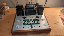
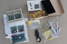
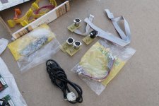
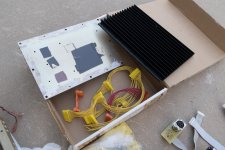
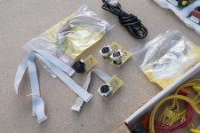
Power Supply:
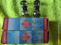
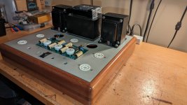
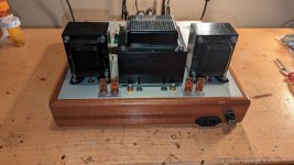
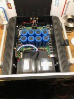
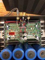
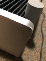
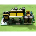
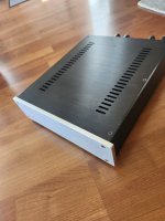
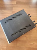
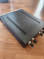
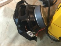
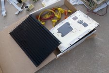
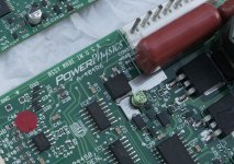
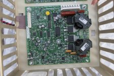
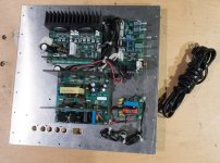
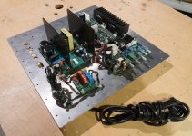
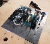
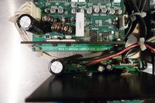
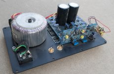
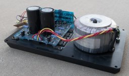
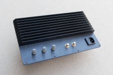
Metal case from eBay (second image is basically the same item with a similar layout to what mine will look like)
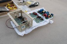
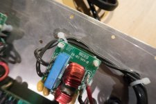
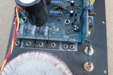
R-core transformer from eBay (15v-0-15v)
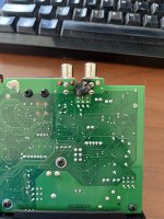
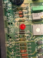
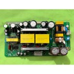
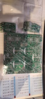
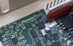
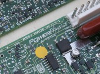
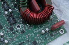
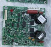
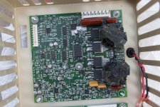
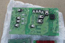
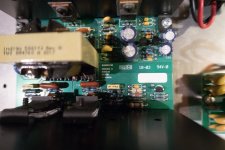
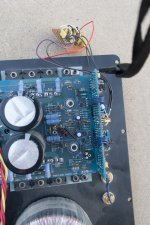
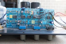
Sigma22 board from eBay
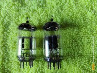
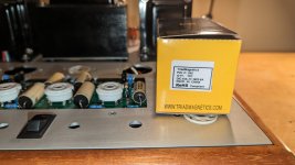
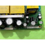
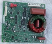
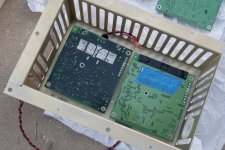
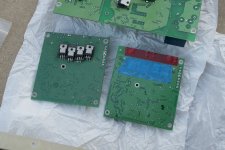
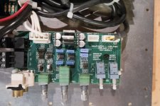
Silkscreen/Circuit sides of board, for reference
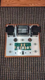
Phono preamp:
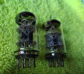
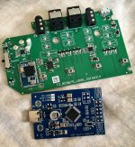
Akitika preamp board (
https://www.akitika.com/PhonoPreamp.html)
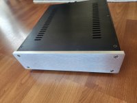
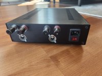
Case from eBay
My Primary Questions (Safety related):
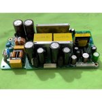
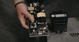
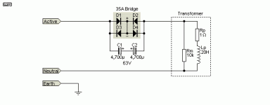
1. The R-core transformers have a built in GWG (mains ground) wire, I plan on obviously connecting this to the GWG pin of the IEC connector (per the example power supply image), however should I also ground the power supply chassis to the same IEC ground?
My thought/plan is: YES
2. Because of the above, and because of the example image above, am I able to bolt the transformer directly to the chassis, or should I use either standoffs (at least for increased airflow around it for heat dissipation) or possibly even insulate it using nylon bolts/washers?
My thought/plan is: BOLT DIRECTLY TO CHASSIS
3. The Sigma22 board - should I ground the DC 0v side to GWG, as well?
My thought/plan is: NO
4. The Sigma22 board - can I use standard metal standoffs for this or should I try to use nylon hardware for isolation purposes?
My thought/plan is: USE METAL STANDOFFS
5. The female 3-pin connector on both the PS and the preamp chassis, should these be insulated from connecting the chassis metal or do I want them contacting the chassis metal for grounding purposes (or does it not matter)?
My thought/plan is: DO NOT INSULATE THEM FROM CHASSIS
6. For safety purposes ONLY (both shock hazard and risk to damaging either/both boards - not talking about feedback loops, etc., yet): should any part of the preamp chassis and/or Akitika board be also grounded in some way (obviously the 0v DC ground will be connected to the Sigma22 board)?
My thought/plan is: NO, outside of whatever is decided subsequently about potential feedback loop grounding
My Secondary Questions:
7. My turntable has a ground wire (I installed, it originally didn't) that I will be connecting to a knurled nut grounding post on the back of the preamp chassis. I'm having a difficult time discerning how best to ground this from this point based on all the different things I've read (including from Akitika as their board is "meant" to be included in their larger amplifier setup in the same chassis and, ultimately, is grounded to its chassis which is obviously GWG).
I know hum/"ground loop" grounding is a hard concept for most to grasp (outside of those with vast electrical knowledge/experience, of which I am absolutely not) and can be a rabbit hole at times, so I don't necessarily expect an answer on this but curious in case someone has an obvious and (hopefully straightforward) answer. I've read through this article (
https://diyaudioprojects.com/Technical/Grounding-Shielding/) and assume something like this would work, however I don't fully grasp what he's talking about and therefore how to implement it (I am entirely a visual person, if this were drawn out I'm sure I'd follow but just reading through text is hard for me to understand exactly what's going on, especially being inexperienced with the nuances of electrical engineering terminology).
8. One final, dumb question - the PSU case I bought has a LCD voltage readout screen that I'm hoping I can hook up. My questions are: since this is just a 2-wire DC unit, do I hook it up to the Sigma22 +15V and 0V, or the -15V and 0V, or does it not matter? And, subsequently, and this might not be obvious without knowing the part, but can it handle/read the ~15V, assuming it's usually used for 12V?
Anyway, as I mentioned previously, I absolutely appreciate any and all help with this, and thank you for taking the time to read this if you've gotten to this point, and even more so if you decide to respond. Please feel free to completely rebut any of my "thought/plans" above, etc., in your responses and just generally tell me where I'm wrong (or right) and any general concerns/red flags you might see with any of the above.
Cheers