Gauss meters, any reviews?

Anyone know much about gauss meters?
Just wanting to measure strengths of permanent magnets for projects ranging from massive subwoofer builds to robotics? Neo, Ferrite magnets what ever.
Not to expensive maybe under $400 or $500 obviously cheaper the better like it doesn’t have to spot on accuracy but a reasonable one would be good!!

Any recommendations?
Cheers

Sound of various Pass amps

Sound of various Pass designs

Nelson,

It would be interesting to know your thoughts on how the Sony VFET amps sounded vs the Pass SIT amp vs the current (and maybe past) Pass 240 based products, the F series and maybe even the Aleph sound.

Perhaps a short description of each and what that design did really well and perhaps what it could have done better. Also perhaps how it performed into low impedance loads.

I realize how each sounds is subjective and all have sounded good. However, since you're likely one of very few people who have heard each topology, your perspective on each would be great info to know. I also think it could be useful for folks buying Pass equipment (new or used) who are wondering how a particular piece might fit into their system. Finally, it would also help those interested in DIY who may be trying to determine what to build. Essentially, it could serve as a guide that would evolve over time and could even perhaps be a sticky.

I realize you have a long list of to-do's, but given the number of designs over the last five years or so, I think it would be very useful. As this site has grown, it's become very challenging to wade through thousands of posts on each design to try to determine how each compares to others.

Thanks,

Steve
  • Like
Reactions: Freedom666

0.68uf paper oil caps any use in audio?

Also got some 0.1 here all made by rubycon.
If they have no use in audio I will move them on, but I know people go crazy over paper oil caps, but don't want to hoard too much stuff!
They are rated at 1500V, so may be useful in high voltage circuits that use transmitter tubes perhaps?

Attachments

  • 16969795595417605384334287915280.jpg
    16969795595417605384334287915280.jpg
    435.1 KB · Views: 246

AIKIDO Glassware Preamp

To the point. I have a Glassware Aikido preamp that I have decided to sell for $500. Free shipping within lower 48 states. The unit was built with the following:
1) Manley Labs RCA jacks
2) All silver plated copper wiring.
3) Obbligato copper output caps 600V
4) Special connections to allow tube access to be easier for the owner
5) Glassware PS-21 Power supply made for this application
6) Quality Hammond chassis.

Attachments

  • PB010002.JPG
    PB010002.JPG
    128.2 KB · Views: 272
  • PB010004_01.JPG
    PB010004_01.JPG
    733.8 KB · Views: 233
  • PB010008.JPG
    PB010008.JPG
    306 KB · Views: 231
  • PA310004.JPG
    PA310004.JPG
    276 KB · Views: 214
  • PA310005.JPG
    PA310005.JPG
    251.2 KB · Views: 211
  • PA310008.JPG
    PA310008.JPG
    256.2 KB · Views: 239
  • PB010001.JPG
    PB010001.JPG
    414.3 KB · Views: 233
  • PB010002.JPG
    PB010002.JPG
    128.2 KB · Views: 253
  • PA310001.JPG
    PA310001.JPG
    522.9 KB · Views: 266

Sony TA E86B power on issue

Hello. So I am the happy owner of a TA E86&TA N86 set and ever since I got the TA E86 preamp I have some strange issues with it, mainly when I cold start it.

After the 5-6 second delay from when I switch it on, there is a strong 1 minute of really strange noise, more specifically, there is some strong pink noise followed by a strange oscillating sound, just like when you play those 20hz -20khz sine waves, and then a pretty loud pop after which complete silence occurs. Turning it on and off after being on for some time does not replicate the sound. It only does this after it has been turned off for at least an hour or so.

The preamp has seen some servicing, some caps have been changed, but not all. To me, it sounds like a failing old cap that is charging, but looking at the schematics, after the 5-6 second mute sequence from the moment you power it on, there are three small caps on the power supply board that charge and those caps have been replaced.

I would appreciate a fresh input on the matter since it is pretty annoying and I really like this set so I want it fully working. Thank you!!

Attachments

2x IRS2092S bridged

Hi, I built an amp that uses two smps 12v supplies fed into two 12v to 60-90v stepups creating a dual +-60-90v power supply for an irs2092s amplifier

If i wired 2 irs2092s chip amps in parallel to the dual supply instead of one, could I wire the amplifier outputs (bridge?) to get over 500w and how?

At the moment I'm just using one irs2092s amp that succesfully supplies a subwoofer with max 500w

Also I have the option to set the supply voltage from +-60v to +-90v
What's the safest voltage of the irs2092s amp that provides the best performance
Amp
Stepups
Smps

Attachments

  • Snapchat-875310902~3.jpg
    Snapchat-875310902~3.jpg
    57.2 KB · Views: 219

Latency with Allen & Heath ZED i-10FX interface

Hi! I am wondering if I could get some pointers on how to better use A&H ZEDi-10 as an USB interface with a Linux-based DAW for live sound. My current problem is a noticeable albeit small latency between the plucked guitar string and the sound from the monitors. I suppose it should be fixable because if it is noticeable for a beginner like me, it would be unusable for professionals.

I am a beginner, and I have finally gotten around to trying my newly acquired Allen & Heath ZED i-10FX mixer as an interface. It can send 4 independent channels via USB. I installed Ubuntu Studio distribution, with low-latency kernel, and trying with Ardour 6, which comes with it.

The interface work out of the box with this setup but I hear that delay. I know next to nothing about DAWs yet, I was barely able to figure out how to configure the Ardour session to receive and send the sound back. So, perhaps I need to adjust some parameters from defaults.

I use ALSA as sound engine/bus but I also tried JACK with no difference in the delay. Googling suggested that for simple use like mine - playing a single guitar through - there is no advantage of JACK over ALSA, and Ardour itself recommends ALSA.

I tried to calibrate the latency by plugging the monitor out into the guitar in and running the calibration in ardour - it worked, and I got 81 but I am not yet sure what it means, whether these are even milliseconds or frames or something else.

I am also using a pretty powerful i7 quad core 12th generation laptop, so I should not have a bottleneck there.

Any suggestions? Thanks!

TDA7294 high pass filter

Hi! I have Edifier s730 2.1 system based on TDA7294, 150W+75W+75W
I want to change the value of high pass filter for satelits, now is around 150hz, i want it from 80 hz
Can someone help me with changing the value of Capacitors and Rezistors , and what rezistors and capacitors to change,to get 80 hz frequency
Please help me guys, i am planning to change satelits and i want a good mid bass for my system.

Attachments

  • TDaa7294.png
    TDaa7294.png
    123.9 KB · Views: 176

For Sale Khozmo shunt Quad 10K attenuator, Noble stereo 10K, Alps RK40 stereo 100K

I have some pots/attenuator that I currently have no need, so trying to find new homes for them.

All are shipped from Singapore, depending on my work schedule.
For any order more than $100, I’ll do free shipping. You could combine with my other T.I parts sale thread too.

1. Khozmo 48-steps Quad 10K
Perfectly for any balanced solid state preamps or headphone amplifiers. Brand new.
$230 shipped worldwide.

2. Noble 10K stereo
I have 4 of these. All come with pre-soldered boards but still unused. Much, much prefer the Noble to the Alps RK27.
$35/ea plus $12 shipping for whatever quantity.

3. Alps RK40 100K stereo
Another great pot. They no longer made these anymore, still a better choice than the TKD 2511.
This one is used and pre-soldered, fully working.
$50 plus $12 shipping.


CBC9A7A7-A28E-45A0-B4F3-D0063078593E.jpeg
798E34E0-1BF0-47A7-A794-FE7C07589A46.jpeg
82B8866F-6BAF-45E3-AEC4-2CA435121671.jpeg
45C480D4-F595-4ABD-A857-3CB19CC4A2FE.jpeg
53CFB81C-9E91-4A4D-AACF-6B1E7427513A.jpeg
D101BB80-C664-4112-BD31-CA2D02471B11.jpeg
ADC3AA1C-DE68-4588-B8D1-F1ECCC70E4F4.jpeg

Sony CDP-337 Restomod

Heh Restomod... Going to try and document this here for others to follow / ignore as they see fit

Bought a Sony CDP-337 with a wonky mech. I already have a CDP-227 but this is a step up. Electrically similar is correct but doesn't tell the whole story at all...

that wonky mech first of all. Wonky, as in "drawer doesn't open" 🙁 You can YouTube but it was not quite so straightforward as I thought the lithium grease I had was too much for the rails, so don't do that! Grease for cogs thin oil for slides. Couples with new belts, the drawer now slides out of the player as it's supposed too.

There is a lot going on in this mech and it is satisfying to watch without the lid as the disk is lowered onto the spindle during the loading process

Finds and reads even CD-R's without fail

I'll be coming back to this as I progress...

Andy
  • Like
Reactions: xman2005

ADC Sound Shaper Two analog meter adjustment?

I need to adjust the sensitivity of the analog meters on this ADC Sound Shaper Two equalizer. I have the schematic but the service manual I have is for the LED version so the calibration is different. See schematic I marked up: I marked the front panel adjustment (yes they are all the way up).

To me it looks like VR103 and VR104 will adjust the sensitivity of the meters. Am I correct?


meter adjust.jpg

ADC lowrez.jpg

I have a couple of weird Aleph J problems

My Aleph J sounds wonderful for the most part, but I have a couple of problems that I would like to address.
First one: with no input or output connected and the amp powered on everything looks normal meaning all the Leds are lit as they should be. When I power off the amp the PS Leds take about 1 minute to go completely out. However, with the speakers connected and I power off one side immediately goes dim while the other side is normal.
What could this be?

Second problem: if I reverse the input connections, I get no output from either channel, but the other way works perfectly. I have no idea what to look for to solve this issue.

any advice would be greatly appreciated!!

Mixing and matching RMS

Im installing a Kenwood KDC-X705 along with a SKAR RP600.5 amp to replace the Harmon/Kardon factory junk of 27 years old. The RP600.5 fits perfectly lengthwise where the original was located and has the speaker connections that are perfect too. I like it because I intend to use the 5th channel for a KICKER 43C104-N bundle sub box.

I tried Skar 6.5 coaxials in the front doors and those were aweful sounding. Nothing there!
I've now swapped in TX6.5 loud speakers. Wow, what a difference! Those crank for a super budget price. Will they last and for how long?

The front doors can accomodate one 6.5" and one 4.5", each mounted close together and each has a separate wire from the original amp location.
I want to run the Skar TX4, mid/tweeter in the 4.5" location.
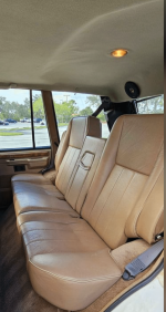
The vehicle has 4.5" speakers in the rear above the hatch in the headliner. I wanted to run those too, but substitute 6.5" somehow.
If I forgo the rears, I could use chs 3&4 for the TX4 mid/tweeters and tell the Kenwood Excelon to compensate via its crossover programming.
I want to combine the TX6.5 loudspeakers with the TX4's and possibly use a crossover (do they need it) and connect speakers in the rear, more TX6.5's

I've heard that I don't really need rear speakers but they are nice to have when the rear hatch is open too and more MID for that size speaker is nice.

Should I forget the rears and use the amp's 4 channels on the fronts only, or can I get away with powering the fronts together on 1&2 channels, and the two rears on the chs 3&4? Will a XO be needed on the front or can the AMP be tuned to compensate?

Skar TX6.5 RMS 150W 100-8000 Hz
Skar Tx4 RMS 60W (pair) 60-21,000Hz

I hope I made that clear.

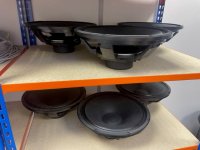
Attached is an example of someone putting a Kicker 46CSC654 in the headliner.
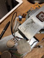
Attached is the door configuration of the 6.5 and 4.5 speakers.
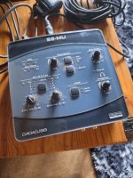
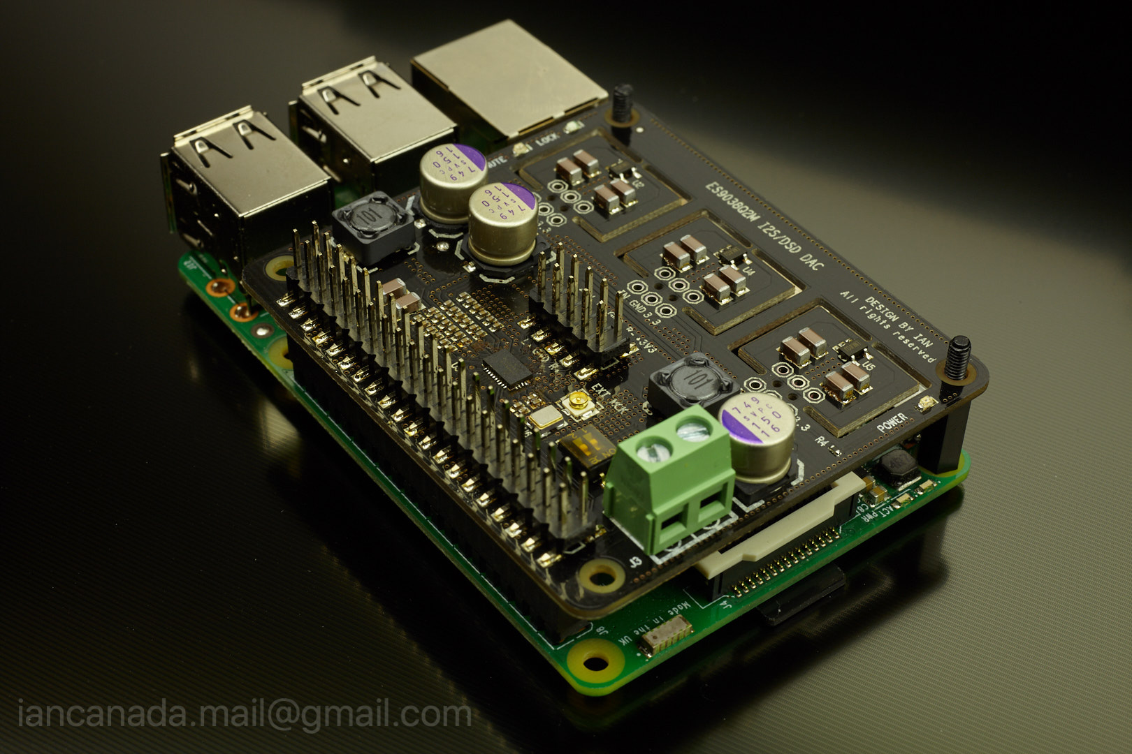
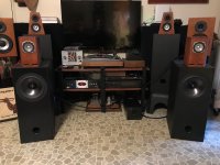
Screen Shot 2023-11-08 at 1.02.12 PM.png

Attachments

  • Screen Shot 2023-11-08 at 12.56.38 PM 1.png
    Screen Shot 2023-11-08 at 12.56.38 PM 1.png
    488.6 KB · Views: 73

2 Counterpoint SA 12s, run one channel in each amp for stereo

I have, in my infinite wisdom (please dont tell my wife), acquired 2 Counterpoint SA-12s. One has a blown mosfet in the left channel, the other has a blown mosfet in the right channel. Is it nuts to think about running the amps as one channel amps. Since the rail fuses and gate resistors are blown or fried, one channel is inoperative. I am assuming each channel produces approximately 40 watts. Should I also remove the 6 DJ8s from the inoperative channel? and the output fuse (s). Tell me why I should not, must not, can not do this?

RS180-8 sanity check

Hey everyone,

I'm in the process of building my first set of speakers. I started about six months ago and haven't had as much time as I wanted to work on them. Unfortunately I'm nearing the end of the cabinet build, and can't find my original notes on what I was actually going for. I've used WinISD and the various online websites, but they all give pretty different results using the same parameters. For example I think on Dayton's website for the RS180-8 it says for a Ported enclosure a volume of around 12.5L is ideal, but one of the online calculators says around 10L is best.

Anyways, I built enclosures that are roughly 13.9L without taking into account anything inside. Taking into account my bracing, the port volume, and the speakers themselves, I figure that puts me around 12.5L, which I imagine is what I originally set out to do since it's close to what Dayton recommends I think.

Putting that into WinISD and a box frequency of around 45Hz with a port of 4.3cm shows a port length of around 14cm and a 3dB frequency of around 46.5 Hz. Does that all sound right? My plan was to use the Monacor BR-50HP bassreflex port, which is 4.3cm x 141.mm, which is basically spot on.

Anything I'm missing here or should be doing differently? I can't increase the box size at this point, but I could drop it with some more bracing if for some reason that made sense.

Thanks.

Newbee question on LTSpice

Started with LTSpice basically today on OSX. Drew up my first schematic, based on some reverse engineering of a tube amp I built yeears ago.
Entered the first stage, the phase splitter. Ran a simulation (.tran) with a 200Hz input @ 25 mV. Was expecting to see 2 signals 180 degrees out of phase on the outputs. But the simulation shows the both outputs in phase.
As this is a cathodyne circuit that would be impossible, and o'scope measurements confirm I get 2 inverted signals out. So I must be doing something wrong in LTSpice, but cant figure out what. ASC attached.
This is the sub file I'm using:
* * Generic triode model: 12AX7 * Copyright 2003--2008 by Ayumi Nakabayashi, All rights reserved. * Version 3.10, Generated on Sat Mar 8 22:41:09 2008 * Plate * | Grid * | | Cathode * | | | .SUBCKT 12AX7 A G K BGG GG 0 V=V(G,K)+0.59836683 BM1 M1 0 V=(0.0017172334*(URAMP(V(A,K))+1e-10)) ** -0.2685074 BM2 M2 0 V=(0.84817287*(URAMP(V(GG)+URAMP(V(A,K))/88.413802)+1e-10)) ** 1.7685074 BP P 0 V=0.001130216*(URAMP(V(GG)+URAMP(V(A,K))/104.24031)+1e-10) ** 1.5 BIK IK 0 V=U(V(GG))*V(P)+(1-U(V(GG)))*0.00071211506*V(M1)*V(M2) BIG IG 0 V=0.000565108*URAMP(V(G,K)) ** 1.5*(URAMP(V(G,K))/(URAMP(V(A,K))+URAMP(V(G,K)))*1.2+0.4) BIAK A K I=URAMP(V(IK,IG)-URAMP(V(IK,IG)-(0.00058141055*URAMP(V(A,K)) ** 1.5)))+1e-10*V(A,K) BIGK G K I=V(IG) * CAPS CGA G A 1.7p CGK G K 1.6p CAK A K 0.5p .ENDS

I also loaded the schematic in LTSpice in a windows VM , but result was the same.
Any hints appreciated.

Attachments

Quick question!

Hi, I needed voltage regulators positive and negative 15v I think for my active filter ( high pass , low pass ) to power the op-amps.
This is all I could find at the moment in stock, are they fake? , china versions, Good enough to use them ? or should I trow them in the bin.

Also, how about just transformer - bridge rectifier - a couple of capacitors = dc -+ 12 - 15v ?. or you recommend Voltage regulators?.

Attachments

  • chnn.JPG
    chnn.JPG
    158.1 KB · Views: 113

Hello from Canada

I was on here maybe 15 years ago, no idea what my username was.

My dad's on here (Trigon?) and Daniel (his friend) they used to build stuff together. My dad built Nelson Pass Class A 100w Mono Block per speaker and custom KEF based standing speakers that were biwired as per 107.2 REF and the B220 woofers with the connected rod and Kef 104.2 Mid and Twitters. He sold those and recently is back with KEF 104.2 that he recapped, reinsulated and did the ferrofluid on.

Daniel built me a headphone mini amp years ago and he was building his own amps. He had if I recall Martin Logan standing speakers with custom fancy Raven ribbons and a bunch of other cool stuff including a fancy Vinyl player setup.

Me, well, I'm getting started, making a purchase for some KEF 107.2 tomorrow and will be on the hunt for a Class A amp suited for this puppy. On a budget right now, but long-term will want probably something like my dad's mono blocks.

I will use a minipc and feed out from high resolution TIDAL and FLAC files, so will be looking into some kind of PC DAC to AMP.

I will probably for the fun of it get a vinyl setup too down the line.

Loudspeaker for current drive

Are there technical ideas for designing a loudspeaker especially for current driven amplifiers? This could be special CFA amps or voltage driven amps with resistors in line.

I have some propositions on that topic.

Current drive with voltage driven amps can be realized with the "simple resistor method" as described by Esa Merilainen (website current drive info).

Nelson Pass tested this method with higher value resistors like 50 ohms. Merilainen describes first benefits putting a resistor with the same R like the driver 4 / 8 ohms in line with it.

Many voltage driven amps work with an impedance like 3 to 4 ohms giving most wattage.

A loudspeaker - for example a fullrange driver should have 1- 2 ohms voice coil resistance so that 2-3 ohms added push the amp into "beginning" current drive.

Putting several drivers parallel as a line driver would do the same concerning impedance but not everyone wants a line driver array.

Voltage driven amps with the simple resistor method can be a choice with loudspeakers having a Faraday / copper ring on the pole piece which brings distortion already down. Adding a resistor in line makes the sound better - very close to real CFA (current feedback amplifiers) amplifiers what I found out in a listening test.

Often Multi way speakers have resistances in line with tweeters and midrange drivers. That is the reason why many do not feel the need to try out current feedback amplifiers.

CFA amps would profit from special loudspeakers which have a lower mechanical Q. As the bass resonance is less controlled in this type of amps.

However all my tests with basic current feedback amps did not show any necessity for taming the resonance.
  • Like
Reactions: tmuikku and GM

Fun with active feedback!

Preparing a paper about active feedback, sharing these counter-intuitive results might give some insight in the operation of amplifiers.

Shown in the illustration, IOP1 and IOP3 (Tina-TI simulation, IOP='ideal opamp') have their inputs swapped, but not the active feedback operational amplifiers IOP2 and IOP4. The feedback network consisting of R2 and R3 are identical.

Both circuits behave as inverters, what was not immediately expected with the IOP1/IOP2 configuration, whereas it was obvious with the IOP3/IOP4 configuration.
To avoid lengthly derivations of formulas, consider the outputs of IOP2 and IOP4 as "Vz", being -(R2/R3)* Vout.
For the IOP1/IOP2 configuration, Vout = Ao * ( Vin - Vz ), which boils down to Au = -R3/R2!
For the IOP3/IOP4 configuration, Vout = Ao * ( Vz - Vin ), which boils down to Au = -R3/R2!

Concluding that not the forward configured amplifier (IOP1, IOP3) determines the overall performance, but the active (in this case) controller (IOP2, IOP4).
Notice that amplifiers in general behave less then perfect at extremes (high frequency, start up / shut down sequences, to name just those two), and the poltergeist Murphy (In Ravels Gaspard de la Nuit named Scarbo) can pop up everywhere, mostly quite unwanted...

Other more developed similar circuits (a passive feedback in IOP1/IOP3 or non-inverting feedback controlling IOP2/IOP4) show none to less favourable solutions, as a simple resistive divider and a buffer has proven already.

And I promised N. Pass a headstart, so here it is.
R1 is left out (obvious, no real zener here), μ is approx (R3/R2)^2.

Attachments

  • Funwithactivefeedback.jpg
    Funwithactivefeedback.jpg
    339.7 KB · Views: 155

Fireplace sub

I'll skip the long backstory. Is it possible/feasible to build a subwoofer into this corner fireplace/TV area? The rough volume is about 60 cu ft. (equilateral triangle with two 56" sides yielding an 80" face, about 75" tall after a divider is accounted for). Yes I know it's not an ideal sub box, but we're trying to maximize space and avoid building an entirely separate box just to sit on top of, what is effectively, a giant box. Also, the sides are about as rigid as you get (framed house exterior on two sides, thick tile on the face) so that's a big plus!

We're not looking for crazy high SPL, more concerned with extremely low bass and overall SQ vs an off-the-shelf solution. I'd love to get flat to 35hz if possible. Since it's lower SPL, we're hoping the fireplace wont' rattle, but it's a risk we're willing to take.

1. Is this at all feasible or just completely ridiculous?
2. If feasible, what driver would you recommend?
3. Ports? Batting? Any other suggestions to maximize results (given obvious constraints).
4. Even after all that, are we likely to get better results from a MUCH smaller, but properly designed and/or built 15" or maybe even 18" sub? I'd like to go passive, so something like a JBL MRX or EV (I come from the pro audio world, so not too familiar with equivalent home stereo boxes)

Thanks fellas!

Attachments

  • 2693729235946367451.jpg
    2693729235946367451.jpg
    364.2 KB · Views: 148
  • -3799719391863699679.jpg
    -3799719391863699679.jpg
    80.4 KB · Views: 142

Help with SOTA turntable power supply connection

Need help here. Can someone help me connect the grey power supply wire - 2 cables, one with a red line and one not, both register voltage going through them - to the motor board? Where do the grey wires go? To the white box or the black box behind it and where on the appropriate box? This is a replacement motor that somebody gave me for my dead one and has this white connector box. In my old motor the grey power supply wires connected to the black box where the red and orange wires connect to. When I put my multimeter cables on the orange or red connection on the black box I can't find another input
IMG_2220.JPG
IMG_2221.JPG
IMG_2203.JPG
IMG_2222.JPG
that is connected (beeps).


Thanks.

Attachments

  • IMG_2221.JPG
    IMG_2221.JPG
    540.2 KB · Views: 89

For Sale 6pcs Beyma 15P80ND + recone kit

I started to design my own speakers during the pandemic and went a bit wild with buying drivers so I am having a clearout of parts I don't think I'll ever use.

six Beyma 15P80ND
two recone kits

One of the speakers is damaged from mishandling and was a superglue job at the time. They have never been using in anger!

I was going to replace the cone and so have two recone kits with one spare if the first repair was no good! I never got around to it.

I'm offering these amazing drivers for £1200 for the six + recone kits.

Collection from Nottingham only.

Attachments

  • sp1.jpg
    sp1.jpg
    58.5 KB · Views: 169
  • sp2.jpg
    sp2.jpg
    72.7 KB · Views: 172
  • sp3.jpg
    sp3.jpg
    71.9 KB · Views: 161

Madrigal Carnegie One - which Load Impedance ?? (MC Cartridge by Mark Levinson - close to Luxman's LMC-1 and SONY's XL-MC7)

I don't know of any other MC cartridge where the recommended load impedance in the specifications covers such a wide range (between 30Ω and 50.000Ω resp. 50KΩ). Maybe a missprint ?

According the frequency response (go to the attached files) the a lower value arround 30Ω-40Ω seems more likely to me (as long as the measurement for frequency response was carried out without using a load impedance).

Under
https://forum.audiogon.com/discussions/thoughts-on-the-madrigal-carnegie-one
I read this:
During the reorganization of Benz, a collaboration was arranged between Van den Hul, Mori and Lukaschek. Lukaschek already worked for Benz, and Mori was well-regarded for his contribution in the development of the Sony XL55 cartridge which employed a novel coil. Everyone knows about A.J.Van den Hul, of course. The work of the men resulted in the production of the Benz Silver, the Van den Hul One, and the Madrigal Carnegie One.

Like the Sony moving coil, the Carnegie One has an unusual figure eight coil design. Another feature is that the Madrigal has a layered cantilever made from carbon fiber, beryllium, and aluminum. No other cartridge that I am aware of ever used this exact cantilever composition.
The cartridge shares a common tip with Van den Hul models, the true line contact that Van den Hul designed.

Like the Sony, many examples tend to be low-riders over time. That said, if it doesn't ride low in the groove now you will probably be okay with it. If it does ride low, however, take a pass because the body is not easily opened for repair. That is the only mechanical downside that comes to mind. I own two, and one came as a low-rider. Check it before you buy it.

How does it sound? Everyone has a flavor he prefers, but reviewers at the time considered the Madrigal Carnegie One to be one of the most neutral cartridges ever made, and most of those guys ended up with one in his stockpile. I find the sound to be very clean, but not overly exciting. Still, it is a nice cartridge worth owning that is still capable of beating the performance of a lot of today's offerings.

If you get it, it has a Dynamic Compliance of 17 x 10-6 cm/Dyne, so it will work well with a wide range of tonearms. As far as VTF goes, mine seems to like 1.6-1.7 grams. I haven't used it in awhile, so I can't tell you exactly where I used it last, but it in that range.


Under
http://www.pladespilleren.dk/HIGHfidelity/HF 1987-3 Carnegie One VdH MC10.pdf
there was reviewed this cartridge together with Shinon Red, VDH MC10 and Kuetsu Rosewood Signature (mounted on a SME V ton arm)

But I don't find any advice concerning the best suited load impedance.

More URLs:
https://www.audioasylum.com/audio/vinyl/messages/72/723119.html
https://www.audioasylum.com/audio/vinyl/messages/72/723168.html
http://www.koerner.de/michael/Sony_Yoshihisa_Mori.html (BENZ)
https://www.stereonet.com/forums/topic/114837-fs-madrigal-carnegie-one-mc-cartridge/ (Load Impedance: 47K)
https://www.vinylengine.com/turntable_forum/viewtopic.php?t=65980 (Load Impedance 40 Ohms)
https://www.canuckaudiomart.com/det...drigal-carnegie-1-moving-coil/images/3413056/ (30 ohms to 50K)
https://www.vinylengine.com/turntable_forum/viewtopic.php?t=65980
https://audiokarma.org/forums/index.php?threads/madrigal-carnegie-one-lomc-cart-levinson.43927/
https://pinkfishmedia.net/forum/threads/mark-levinson-madrigal-carnegie-one-not-working.109859/


both this cartridge and LMC-1 from Luxman - go to
https://audio-database.com/LUXMAN/etc/lmc-1.html
https://www.hifido.co.jp/sold/05-24854-58469-00.html?LNG=E
https://audio-database.com/LUXMAN/etc/lmc-1.html
seems to be a derivat (rebadged version) from SONY's XL-MC7 - go to
https://images.hifido.co.jp/14/046/04675/b.jpg
https://i.pinimg.com/originals/81/94/d1/8194d155578ffac0dc6e2e21b0dd11d6.jpg
- at least according various URLs like those under
https://forum.audiogon.com/discussions/luxman-releasing-a-mc-cart-in-japan?sort_order=desc
and
http://webcache.googleusercontent.c...org/sony-XL-MC1.html&hl=de&gl=de&client=opera

If this is right, the electrical characteristic compare to the Carnegie ONE are nearly the same, then the recommended load impedance on Luxman's LMC-1 according
https://audio-database.com/LUXMAN/etc/lmc-1.html
https://www.hifispeaker.wiki/item/sony-xl-mc7
is a good start for investigate the sonic behavior:
Head amplifier : 40 Ω or more
Step-up transformer : 3 Ω or more.

Concerning SONY's XL-MC7 - go to
https://www.hifispeaker.wiki/item/sony-xl-mc7
http://20cheaddatebase.web.fc2.com/needie/NDSONY/XL-MC7.html
is no mentioned different resistor values between step up transformer and head amp use (30 ohms coil imp.,100 ohm or more for load impedance).

Where I can find the correct information regarded the right load impedance (maybe there are test reviews, who this is explain) ?
Thank you very much in advance.

P.S.: various MC cartridges need in additional a capacitor for a flat frequency response - go to
http://www.extremephono.com/Loading.htm (fig. 2).
Maybe even this cartridge ?

Attachments

  • madrigal-carnegie-one var views.jpg
    madrigal-carnegie-one var views.jpg
    292.8 KB · Views: 119
  • madrigal-carnegie-ONE package.jpg
    madrigal-carnegie-ONE package.jpg
    31.3 KB · Views: 112
  • High-Fidelity issue 1987-3 Carnegie One VdH MC10.pdf
    High-Fidelity issue 1987-3 Carnegie One VdH MC10.pdf
    1.2 MB · Views: 114
  • madrigal-carnegie-one spec.jpg
    madrigal-carnegie-one spec.jpg
    59.7 KB · Views: 115
  • madrigal-carnegie-one freq. resp-II.jpg
    madrigal-carnegie-one freq. resp-II.jpg
    46.1 KB · Views: 97
  • madrigal-carnegie-one freq. resp..jpg
    madrigal-carnegie-one freq. resp..jpg
    150.6 KB · Views: 106
  • madrigal-carnegie-one.jpg
    madrigal-carnegie-one.jpg
    8.5 KB · Views: 125
  • madrigal-carnegie-one-mc-cartridge (4).jpg
    madrigal-carnegie-one-mc-cartridge (4).jpg
    192.2 KB · Views: 95
  • madrigal-carnegie-one-mc-cartridge (3).jpg
    madrigal-carnegie-one-mc-cartridge (3).jpg
    379 KB · Views: 111
  • madrigal-carnegie-one-mc-cartridge (2).jpg
    madrigal-carnegie-one-mc-cartridge (2).jpg
    176.6 KB · Views: 127
  • madrigal-carnegie-one-mc-cartridge.jpg
    madrigal-carnegie-one-mc-cartridge.jpg
    375.4 KB · Views: 109
  • Luxman LMC-1-IVI.jpg
    Luxman LMC-1-IVI.jpg
    38.7 KB · Views: 90
  • Luxman LMC-1-VI.jpg
    Luxman LMC-1-VI.jpg
    61.2 KB · Views: 94
  • Luxman LMC-1-Luxman LMC-1-V.jpg
    Luxman LMC-1-Luxman LMC-1-V.jpg
    30.8 KB · Views: 90
  • Luxman LMC-1-IV.jpg
    Luxman LMC-1-IV.jpg
    45.2 KB · Views: 100

LND150 noise data

Hi

Has anyone measured the noise of the LND150, or created whatever noise-related spec goes into a spice model for LTspice?

The manufacturer primarily describes it as a high-voltage switch or lamp ballast device, and ... oh yeh... it can be used in linear applications. Being a mosfet, I expect it to be ten times noisier than an average n-jfet, but some real data would be nice to have.

Thanks 🙂

Hi from near Austin, TX

I've not posted here before but just lurking and learning.
I had a question regarding the installation into a 1995 Range Rover Classic.

I've read people think Skar is trash and some think its value for the bucks. My rig is fun to drive but needs music to muffle the road noise, so there is that.

I think I'll head on over to the Car Audio section and see if anybody has experience with installing in my vehicle.

Hook'em horns!

SAE

I’m looking for the SAE, Science Audio Electronic schematic for the following items. I’m converting the following items from 220V back to 110V because I’m moving back to the Unite States.


5000 Impulse Noise Reduction system 110V

2800 Parametric Equalizer 110V.

8000 FM Tuner 110V

2100L Preamplifier 110V

2400L Amplifier 110V

DC servos…..

No, I’m not looking to use a DC servo with a gainclone. Just considering using them AS a DC servo amp where a very low output impedance must be maintained. Not looking for massive output current but higher than +/-15 volt rails IS required As well as fractional ohm Zout (ruling out NE5532). +/-30 to 45 would be nice, more correction range the better.

Is the LM1875 or 3875 my best bet, or should I keep researching? It will be used in a loop with a separate differential integrator, and probably set to a DC gain of around 20.

The Great Great music for equalisation thread

When using an equalizer I often get to a band where there is no music content. Mostly in acoustic trios or other simple recordings. Sometimes i can almost turn it from 12 db plus to minus without hearing a difference.

Please let your suggestions flow. Be it full sounding pieces/recordings or tunes that are revealing in a more narrow band. Perfect or in aspects perfect recordings.

Most importantly: SWEEET MUSIC!!!

- Unless you have a good reason it deserves representation even though it sounds like a sick rooster.

Come come!
Cheers!

Best Temporary Solution?

Good evening all!

My Oris 250 horns and Celestion AXI2050’s are in and I’ve set them up with an active crossover at 388hz.

However, my bass enclosures and drivers are still at least 1-3 months out.

That said- I have two Acoustic Elegance TD18H+ 4ohm drivers I purchased off a member here-

What would be the quickest down and dirty way to utilize them only temporarily for the woofer / bass portion of this setup?

Open Baffle? Quick Sealed Enclosure ?

Thoughts?
IMG_7076.jpeg


I am too impatient to let these sit for 3 months with no midbass!

Thanks in advance.

Doubt HDD Kesu buy in aliexpress

I bought a 1TB Kesu external HDD on aliexpress, I saved 300GB of files on it and opened crystaldiskinfo and victoria I did a quick scan on it and took screenshots

Some people say that these HDDs have modified firmware chinese to hide badblocks and errors and other drives from other manufacturers inside the kase are not HDDs but fake microSD, USB Flash Drive or SSD with less than 1TB

If a 1TB external HDD is fake (case + microSD or USB flash Drive or SSD small storage space) what will appear when opening software such as Crystal Disk Info, GSmartControl and quick scan with Victoria) these programs will deceive as if Was it a legitimate HDD?


Victoria's QuickScan shows some parameter to indicate the HDD does not have bbadblocks and bad sectors and legitime hdd 1tb?

HDD1 Kesu6.png

Attachments

  • 1699443788321.png
    1699443788321.png
    312 bytes · Views: 71

Help me improve my PCB

I'm a total design newbie. In fact, I am really crap at soldering too 😀 anyway, I designed my own guitar/bass "preamp" of sorts - in actual reality, a glorified overdrive stompbox. It's an original design, even though I did take inspiration from various circuits (Rod Elliott's website was instrumental).

Anyway, I really don't know how to go about designing PCBs. The circuit itself should work well enough (it's a bit low in headroom at 9V, but it should work well enough if placed in front of a guitar/bass amp), I simulated the thing countless times and it should be OK functionally speaking.

When designing the (dual-layer) PCB, I tried employing the best practices as instructed by various resources on the web - there isn't much dedicated to analog audio design, really, and everything assumes at least mixed signals - which I can summarise as follows:

  • keep power and signal grounds separate - with a caveat: the design features three dual opamps and two JFETs, so the JFETs have to share grounds with the opamps' power lines
  • put any switching circuitry as far away from the signal processing as possible
  • if power/ground and signal paths run close (on separate layers), then they should try and cross orthogonally rather than run parallel

Now, I can attach a picture of the (computer rendered) PCB, or maybe you need the schematic? Problem is, the silkscreen has yet to be fine-tuned (right now things are a jumble) so it is not really legible.

I also shied away from designing ground planes, since they can be more trouble than they're worth; I only, very timidly, tried making one around the switching circuitry, but I have my doubts as to whether it helps or breaks the design. As of now, it's all done with a star ground.

Advice on output stage of car headunit

Looking for peoples advice/thoughts on an output stage for a headunit I am retrofitting. I recently found the stock headunit for my R33 skyline and out of boredom decided to remake its mainboard to include all of the functionality of modern units while maintaining the looks. I've got a fair bit of experience with data protocols and digital communication in general, but almost nothing with analog signal processing. The UI/display programming is complete, which leaves me with the audio stage to deal with. My original plan was to run the output of a DAC through various digitally controlled analog circuits. I'm now thinking that noise could be difficult to isolate in a vehicle with dirty power from an alternator and a very small form-factor. Would it be a better idea to manipulate the bitstream pre-dac and then do minimal analog signal processing pre amp, or just stick with the original plan of keeping it all analog? I would want eq, low pass, high pass and volume stages (sub amp/speaker amp) and I already have everything to do so with analog ICs. I was just about to start circuit design, but I figured id get some second opinions first haha.

Thanks for any advice/help! It is much appreciated as I am very new to diy audio in general!

If anyone is interested I can post more info about the drivers I made to accommodate the original front panel, but its pretty boring lol

Marantz CD50 - Eject Button Issue - Motor OK

Hi

I have a very tidy Marantz CD 50 with an issue I can’t bottom out.

The deck won’t eject from the button on the front panel or the remote control either. The motor is working and not faulty. I’ve put 5 or 6 VDC across it and working fine. I’ve also replaced the button on the display/control panel for good measure.

I’ve got the service manual but really struggling to get any ideas or a starting point from the schematics available.

Any help will be truly appreciated.

Thanks, J

Acoustic properties of Capacitors - Wurth Electronics testing

I recently received an article from Wurth Electronics on the acoustic effect of Harmonic Distortion caused by Aluminum Electrolytic capacitors. Their findings pretty much agree with what I have observed and measured over the years - decades actually. This information isn't unique to Wurth products, it applies to all electrolytic capacitors.

I contacted representatives at Wurth for permission to post the article here. They agreed after contacting the author, Dr. Rene Kalbitz.

... so here it is as published.

Attachments

MB QUART ONX1.2000D protect cycle

Hey guys got an MB quart onx1.2000D

Cycles power and protect.

Chips on power supply board have been shaved. Does anyone know what they may be using here? So I can pull up a datasheet and check appropriate voltages.

No shorted fets in power supply or output section.

powers up and does start switching on all power supply and output fets (not the cleanest looking though) for about half a second before going back into protect and starting all over again.

seems to have all plus and minus voltages present for a fraction of a second.

Cheers
20231108_120450.jpg
20231108_120500.jpg
20231108_120510.jpg

A tale about non-constant directivity waveguide and horns

This thread has the purpose to investigate non-constant directivity waveguide and horns.

I got interested since it is inevitable to avoid the transition from high directivity at high frequencies to omni-directional at low frequencies. I wish for this to happen over a large frequency range to avoid any abrupt change in directivity.

Much has been done on constant directivity waveguide and horns, so I thought to explore the opposite. Some has been done in this area too, but I'm curious to find out how it sounds like.

Take 1
A slightly modified Kugelwellen horn. It starts at 70 degrees and the overall all curvature is stretched to get a bit more in the wg and less back-fold. I did the calculations some 10 years ago (before kids, 3D-printing and the genius tool ATH was available).

Print is 30 cm wide.
DSC_4509.JPG


DSC_4511.JPG

DSC_4520.JPG

DSC_4517.JPG

DSC_4519.JPG


Was also 10 years I did some measurements...need to freshen up...

TU-8500 phono stage upgrades

I've really gotten the vinyl bug again after finding several large boxes of LPs that I forgot I had, mostly from the 70's. I really am enjoying my 8500 with 8200, always looking for possible improvements. What phono stage upgrades can I make to get even more from the 8500, I love to tweak...Thanks
The 8500 is stock except for the tubes, I'm running Sylvania 12AT7 JAN

Third-wave pipe speaker

The following is from a tntaudio review. I would be interested in opinions.

The smaller Kerr K300 utilise a short transmission line (as in the Bailey approach to minimise overhang and dissipate cone rear energy. The larger Kerr Acoustic K320 uses a hybrid of transmission line and tuned third wave pipe. The familiar Tuned Quarter Wave Pipe (TQWP, often mis-described as a transmission line) has some of the power handling advantages of reflex loading (controlling cone excursion near the system resonant frequency) but fewer group delay disadvantages than reflex. This results in lighter but faster sounding bass and more placement flexibility in the room. The tuned third wave pipe trades some of that excursion limiting advantage in exchange for even lower Q bass tuning knee and deeper (quasi second order slope over 1 octave) extension.

Various stuff free or for sale

I need to clean my place. I am sure we all get that urge from time to time. Honestly, I accumulated too much stuff and instead throwing it away, I will post it here and see if there is interest. Most for free, some for sale, to recover some material purchased.
All I ask if you pay shipping, small flat rate box is ~$11, medium is $17 and large is $23. I will just estimate if it fits.


Update: all attenuators are spoken for.
B1 is spoken for.
Realistic headphones are spoken for.


Now we have second round for Shure riaa.
Added metal hole punching tool for you tube guys and small balancing transformers.
Added thick 12 gauge speaker wires.

JLH ClassA amp and lm1875 boards are gone.
  • Like
Reactions: Bigman80

Class D amplifier problem (HK Audio pro 18 subwoofer)

Dear all,

I have an issue with my build in class D amp in a HK Audio Pro 18 subwoofer.

I have 1 in working order, and 1 is faulty.

What happens is the following:

-If you turn it on, it starts to hiss
-if you play music it is significantly less loud then the one that works.
-after 5 minutes, it makes 1 loud pop then makes a very loud screeching sound and then the red light goes to red meaning ERROR.


Does anybody know what I could do or check to see if some components are broken! I personally think it is the power module or a MOSFET?

Attachments

  • 1538998956_MG_8610.jpeg
    1538998956_MG_8610.jpeg
    17.8 KB · Views: 122
  • 53974_photo.jpg
    53974_photo.jpg
    31.1 KB · Views: 102

Speaker design to carry on a camel, considering Karlsonator

Alright here's the quick and dirty. I've been living with a group of animals (goats, sheep, yaks, and camels) for a number of years now, doing long multi month trips on the trail with them. Starting to get spoiled and wanted to have a throw back to the days where I could listen to music on something other than a cell phone. I need a speaker that is light, size is less of an issue with packing on a camel, and I can always use it as a stool or even have a removable side to use it for storage on the move. But still not much bigger than 20x15x15. I am thinking a mono setup, paired with a high efficiency amplifier that I can power off the 12v battery/100w solar setup I have with me. It will be used outside or in a tent, and will be protected from the weather when necessary.

Pitch me some ideas if you got anything good (or a used amp or driver that you want to sell : ), and I promise to post some pics as this develops. Right now I'm leaning towards some type of class D amp with a .53 Karlsonator, although I'm trying to find a speaker with a neo magnet that could work in this design. Thanks in advance for all the feedback, good to see the forum again!

Chris

Attachments

  • yakspack.jpg
    yakspack.jpg
    98.9 KB · Views: 136
  • Like
Reactions: Arez and Fuling

For Sale Tested Audio Tubes

All tested with my trusty low mileage calibrated TV2 tester.

19 test good 6V6GT. One RCA 6V6GT/G, five RCA 6V6GT (most smoke glass),one RCA 6V6GTA. One Sylvania 6V6GT/G, five Sylvania 6V6GT. Two Ken Rad 6V6GT/G. One CBS 6V6GT. One NU 6V6GT/G. One GE 6V6GT/G, one GE 6V6GT. All $100.

Octet of test NOS close Sovtek 6922 (6DJ8): V1 100,102; V2 102,104; V3 107,115; V4 110,110; V5 102,102; V6 104,105; V7 97,100; V8 103,103 min is 65. All for $100


National 5751 USA 72,70/64 $20


Rare GE 5 star 6189 12AU7WA, s rods 85,85/72 $40.


CBS short black plate 12AU7A 87,90/72 $30.


NOS RCA 12AU7A black plate 85,94/72 $20.


JAN 5U4G RCA match test NOS 105,106/75 $45.


Five Sylvania 5U4GB black ribbed plate top getter test NOS and balanced $50/all.
Will bargain for multiple purchases.

+ ship zelle ppff

Attachments

  • 094D55FC-87C8-4877-86C8-45DFC99D53BF.jpeg
    094D55FC-87C8-4877-86C8-45DFC99D53BF.jpeg
    971.7 KB · Views: 60
  • 3EE518EE-95CF-4B95-9F13-B412E7B2F2C8.jpeg
    3EE518EE-95CF-4B95-9F13-B412E7B2F2C8.jpeg
    901.5 KB · Views: 58
  • 1A63B284-00D9-4D85-B58C-5AF6A4AC389B.jpeg
    1A63B284-00D9-4D85-B58C-5AF6A4AC389B.jpeg
    981.8 KB · Views: 64
  • F1C98D17-3C0C-4875-84B1-B4CD014AC6AA.jpeg
    F1C98D17-3C0C-4875-84B1-B4CD014AC6AA.jpeg
    863.7 KB · Views: 53
  • 7524B6EA-9430-4DAD-A42D-557110812C96.jpeg
    7524B6EA-9430-4DAD-A42D-557110812C96.jpeg
    977.1 KB · Views: 63
  • 5CFA1EFD-834C-47A3-9155-5CFC5161F9BA.jpeg
    5CFA1EFD-834C-47A3-9155-5CFC5161F9BA.jpeg
    861.5 KB · Views: 58
  • 1629C1F4-FA6A-4EF2-8F03-0AA0ADC5D4F5.jpeg
    1629C1F4-FA6A-4EF2-8F03-0AA0ADC5D4F5.jpeg
    762.2 KB · Views: 60
  • 87B53D71-2AB4-4B43-80A2-3B4991FB6126.jpeg
    87B53D71-2AB4-4B43-80A2-3B4991FB6126.jpeg
    492.6 KB · Views: 44

For Sale Hashimoto Iron H-20-7U + C-15-200C + PT-160R + A-105

As it seems I will not be able to finish my 2a3 SET amplifier project due to lack of time, I am selling my Hashimoto iron. All components are in excellent optical condition. Have been running few tens of hours (max. 30h) in a prototype. Coming with original boxes.
  • H-20-7U output transformer pair: 550€
  • PT-160R power transformer (230VAC input): 280€
  • C-15-200CH choke: 250€
  • A-105 interstage transformer pair: 350€
Shipping from Germany within Europe possible.

Attachments

  • A-105_1.jpeg
    A-105_1.jpeg
    397.6 KB · Views: 127
  • A-105_2.jpeg
    A-105_2.jpeg
    305 KB · Views: 118
  • C-15-200H_1.jpeg
    C-15-200H_1.jpeg
    317.6 KB · Views: 117
  • C-15-200H_2.jpeg
    C-15-200H_2.jpeg
    190.7 KB · Views: 129
  • H-20-7U_1.jpeg
    H-20-7U_1.jpeg
    406 KB · Views: 123
  • H-20-7U_2.jpeg
    H-20-7U_2.jpeg
    314.2 KB · Views: 122
  • PT-160R_1.jpeg
    PT-160R_1.jpeg
    298.2 KB · Views: 123
  • PT-160R_3.jpeg
    PT-160R_3.jpeg
    231.6 KB · Views: 122

Dared MC-7P Blown resistors help

Hi,

My Dared MC-7P started making a strange hum. I tried testing and replacing all the tubes, but that didn't work. I opened it up and found two blown resistors, R35 and R36. Now that they are burnt I can no longer read the color coding. Does anyone know what the value of these two resistors is based on a schematic or by looking at your own unit? I can't find a schematic anywhere online and I can't be sure of the values based on any of the photos others have shared of the inside of the unit.

Also, if anyone has thoughts on why these two resistors blew, I'm open to ideas. Without the schematic, I'm not sure of where they sit in the signal path.

You can clearly see the blown resistors in the photo.

Thanks for any and all help.
Jeremy


PXL_20231030_172331602.jpg

ES9018K2M, ES9028Q2M, 9038Q2M DSD/I2S DAC HATs for Raspberry Pi

Since I’ve already made Raspberry Pi capable for DSD playback, I think I’ll need a DSD/I2S DAC HAT for it. Few DSD DAC is available for Pi so far, so I’m gonna design something around.

I’ll pick up ES9018K2M first because basically it’s the 2 channel version of ES9018 (2ch vs 8ch), and I've been very happy with ES9018. Both of them have same SABRE32 Reference DAC core, so good sound quality is expected, here are some speciations:

. Industry’s highest performance 32-bit mobile audio DAC with unprecedented dynamic range and ultra low distortion;
. Supports both synchronous and ASRC (asynchronous sample rate converter) modes;
. Unmatched audio clarity free from input clock jitter;
. 127dB DNR -120dB THD+N;
. PCM384KHz/DSD512;
. Mono or stereo output in current or voltage mode based on performance criterion;
. Supports SPDIF, PCM (I2S, LJ 16-32-bit) or DSD input;
. 64-bit accumulator and 32-bit processing. Distortion free volume control;
. I2C based software control;

Prototype PCB is coming very soon.


ES9018K2MPiPCB
by Ian


ES9028Q2MDAC3
by Ian, on Flickr


ES9038Q2MRaspberryPiDAC
by Ian, on Flickr

Ian
Projects by fanatics, for fanatics
Get answers and advice for everyone wanting to learn the art of audio.
Join the Community
507,493
Members
7,874,567
Messages

Filter

Forum Statistics

Threads
405,588
Messages
7,874,567
Members
507,493
Latest member
Sigismund