I have a Linn CD12, with flight box, and it was fully serviced by Linn in August 2015.
However a couple of years later a fault developed whereby the drawer wouldn't fully eject, without a (very) gentle tug. I've upload a small demonstration to YouTube here - CD 12 Linn drawer - YouTube
Sadly, as you know, Linn no longer services the CD12.
Hoping that I could get this repaired, I sent the player to an authorised Linn repairer, who said that they could not promise, but would try to fix it.
In fact, it was returned to me in a worse state - ie it would not turn on at all! When I questioned them, they wrote me as follows:
"Peter and our Linn engineer worked on your CD for 2.5 hours to try and fix the CD mech, this involved taking the mech in and out of the machine each time it was adjusted and put back in they had to connect and disconnect the ribbon cables that are attached to it. There is no other way of adjusting the mech without taking it out and the ribbon cables loose their connectivity after a while and as you now we cannot get parts from Linn so we couldn’t replace them."
So, to summarise, I have a fine machine (fairly recently serviced) but I'm at a loss as to how to proceed?
If anyone on this forum thinks they can repair it, I'd be happy to consider that. I'm also prepared to consider selling it.
Any advice from anyone as to what my next best step is?
There are several versions of main DC Filter resp. DC blocker to avoid humming and buzzing, if there are DC components by the main voltage. In the PDFattachement I have filed several versions.
What is now the circuit with best reliability for such mains DC filter resp. mains DC blocker to block DC components from the otherwise singing and buzzing toroidal main transformer ?
I guess a corresponding number of parallel EPCOS foil's MKT's together with the suitable anti parallel connected diodes (possibly suitable anti parallel connected diode serial networks of two or three serial diodes)
Or an complete other solution that meets the same purpose is much
more better (e. g. a DC compensation network in parallel mode).
a couple years ago my AKAI AA-1020 got recapped and serviced, and it ran great considering its age. Never could I get rid of the slightest hum, and a pop when switching to/from the radio on the input selector, though I could’ve lived with that. It also makes the infamous power-on thump. (maybe a hint?)
Recently the unit's been developing a heat issue, where the area around the power switch/headphone input/speaker selector on the faceplate gets rather warm - the speaker knob weirdly gets the warmest. After spending an entire day inspecting the power supply/output boards and adjust idling current, the issue was no longer present. Since this morning, however, said area is warming up again, giving me reason for concern. No other issues have developed, the sound is still clear and powerful.
Where should I be starting to look for such a fault? Would the (dirty) power switch come to suspicion?
According to Power Dynamics their 8" Ceiling speaker (PD CSPB8) bottoms out @ 100hz. Is there any point in using a high-pass filter to provide resistance to frequencies they don't respond to?
I ask because I'm considering using of a passive sub. The sub is 6ohms. The ceiling speakers are 8ohms.
Hello! This is my first post here. Nice to meet you.
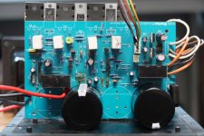
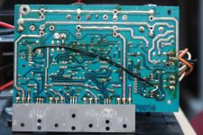
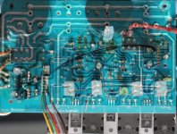
This is a learn by doing project, a chance to learn how to use KiCad and also more about class AB amplifiers. Specifically the Boston Acoustics VR2000 subwoofer I have that needs repairs.
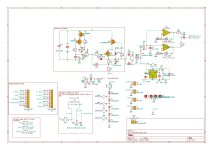
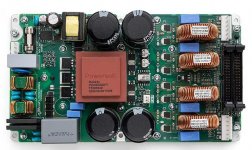
The images below are of the topside and underside of the circuit board, and I overlaid them on top of eachother in the third image to make following parts and traces easier. I drew a KiCad schematic with all the parts as best I could (keep in mind I'm new to the program!). The pdf of the schematic is attached. Some of the parts are difficult to read, especially the 5 color code resistors at times, so some of the values might not be correct. Also the output transistors are in pairs and I didn't feel like drawing extra stuff to keep it simple, so I labeled them and moved on.
Here are the problems. First, the bulk capacitors in the power supply were no good so I replaced C2 and C3. Then it worked for about a week or two, and broke again. The -12vdc voltage regulator failed, so I replaced both U2 and U3, along with their capacitors C13, C17, C18, and C19. Then it worked for a little while and broke again. Or maybe it broke again right away, I don't remember, I've been slowly working on this for a long time.
So right now the main power transistors on the negative rail (Q7/Q9) are shorted out and they pull enough current to blow the fuse moments after turning it on. The output transistors and the resistors on their base and emitter sides are all parallel. I didn't draw it perfectly since I'm barely hanging on to how this thing works, so I drew "Q7/Q9" and "R32/R33" instead of actually drawing out another set of parts.
I bought new transistors for both the + and - rails, a modern complimentary pair was recommended to me (2SC5200-OQ-ND and 2SA1943-OQ-ND). I'm ready to solder those in and see what happens, but that's $13 that can go up in smoke if I didn't fix the root cause, which I'm unsure of 😕
J26 goes to the DSP circuit board full of op-amps and other stuff I don't think is broken. U1 is a speaker protection chip that enables relay RL1 if everything looks good. Q3 and Q2 are part of some kind of feedback loop, I think. Q10 is for biasing the output transistors, I think. How can I tell if this potentiometer is set correctly? I've tried reading about setting bias currents, but I'm not sure how to apply that to this schematic. The bias adjustment is not on the output transistors, so where should I be measuring currents and such?
Yesterday I removed the final four power transistors and powered it up and it doesn't blow a fuse. I tried tracing the audio signal with an oscilloscope and I see a nice sine wave at "AudioToAmp" entering Q1 and Q2, then mostly square waves downstream of that. I'm not sure that's right. What should I see on a scope within the output transistor chain? I think it might change depending on if there is a load attached or not, is this right?
Last, near the power supply is some kind of voltage divider that is used by the feedback loop, formed by a resistor/zener pair Z1/R4 and Z2/R1. All four of those are discolored like they overheat often (see picture below). They may not be working as intended. I think those are zener diodes, but I could be wrong. What are those for, and how can I tell if they are working as intended?
Last last, all of the resistors are 5 band colors, and it's really hard to figure out what's what on some of them. I might have some values wrong somewhere.
Any other obvious things to look for before I solder the new power transistors back in?
I hope there's someone here willing and able to give advice:
Just having received a miniSHARC and Vol-FP kit incl. a 2x8 plug-in (at a good rate 😉) the usage idea is to use this as a 4-way xover. The DACs are located in the active 4-Way speakers, so two SPDIF cables carry the dig. signal to the speakers.
This requires two Stereo SPDIF outputs per side and the miniSHARC handily offers eight I²S outputs.
The remaining hurdle for me: How to/With which device convert the 8 I²S outputs to four SPDIF outputs?
I've searched for a converter and found some for one stereo SPDIF output, but investment for 4 such devices seems high and compatibility with miniSHARC looks questionable as well.
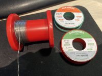
Have had a big spool of solder for many years. It has worked just perfect for all my soldering from wire to the smallest SMD components.
I'm not sure which brand it was as the label has come off, but I think it was Weller, and I'm sure it was containing a bit of Silver.
I'm now trying to get some now solder, but have not been successful yet, and hope someone can help me here
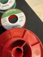
I have bought a small spool of Stannol Sn95,5,5Ag3,8Cu0,7 so that means lead free for SMD (2% flux), and a small spool of Stannol Sn60Pb40 (1% flux)
Both 0,5 mm as is my old solder.
The lead free is maybe a bit better than the leaded, but both is really not easy to apply .... like they do not want to stick on the pcb.
Maybe it is because the old solder has a higher amount of flux .... when using flus on the pcb it flows better, but still not at all like the old solder!!
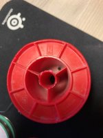
There is small markings on the red spool, H .... something and the number 63/37-E .... might mean Sn63Pb37 maybe .....
I standardized PCB mounting hole spacing and board sizes so I can drop various circuits onto that size and have common mechanicals for future projects.
I was fretting on how to trim the heatsinks to size and get a mirror finish cut. Well a slitting saw on the mill works fantastic. In the video I'm using a slitting blade on the mill with Anchor Lube.
Previous to this cutting operation I drilled the mounting holes and fins on the CNC. I'll be making about 30 of these for future boards. And probably come up with a few other standardized sizes and hole spacings for bigger boards. It should save time over mechanicals all having random mounting holes. A pet peeve I have about people who offer nice PCB's for sale regulators, preamps, stages, etc. then when they upgrade the version they change all the mounting hole spacings! I guess they don't want people to upgrade their projects to the new board version, because they are making people re-drill their chassis a huge inconvenience over just mounting the new version board.
We got into a vigorous discussion of power supply regulators in the Pass P3 Phono Pre thread. (The P3 uses 7815/7915's) To avoid "thread-jacking" detracting from this really nice design by Wayne, I thought it would be appropriate to start another thread. https://www.diyaudio.com/community/threads/pearl-3-burning-amp-2023.404054/
Pick your continent and you've already experiencing 50/60Hz and 100/120Hz on the rails...but there are other nasties which do impair the quality of sound. One of those is the distortion that a regulator error amplifier can inject onto a preamplifier. This was pointed out by a correspondent to the LinearAudio article commenting upon the article comparing various regulator topologies. I did as suggested and le voila, the LM317 (which rated poorly) did have a THD component when a 1kHz signal was injected into the error amplifier.
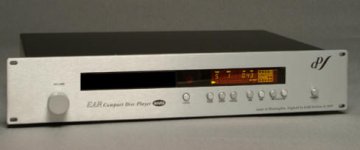
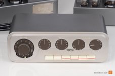
Got my hands on this Ear Yoshino CD-player cheap, but the remote control is missing. It doen't respond to any the remote controls in house, so is there someone who knows what type of replacement remote control that can be used - universal or branded?
Thanks in advance 🙂
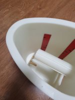
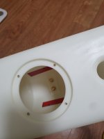
I have a couple of questions about these old Maggies:
1. Electronically there are separate bass and mid panels. I’d like to know if these are capable of being physically separated or is it physically just one panel with 2 electronically separate areas ?
2. If the ribbon protector strips are missing, how easy would it be to otherwise protect the ribbons from damage when transporting them?
Thanks
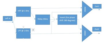
Please find attached the block diagram of Equalization I would like to implement in miniDSP. I have 2 way plugin with me. Is it possible to do it in miniDSP at all, if yes then using which plugin?
I recently picked up a used 97 Lincoln Mark viii with the JBL audio. I'm surprised at how much I enjoy the sound of it. It needs a touch more brightness up top, but that's partly because my ears are old. The linear response down to about 60hz is quite pleasant.
Since the car sat in a garage for a decade before I unearthed it, the speakers have quickly deteriorated in the last 6 months. Surrounds are toast, cones have some dampness damage from condensation, and they're just done. For the first time I'm not looking to really upgrade. I could go the whole way and go HU/amp/speakers, but I'm not really looking to spend a ton on a cheap daily. I just want to pick drivers that will match well with the existing setup and not end up sounding completely different. JBL and Lincoln spent a lot of money on little tricks to make it sound good and be relatively proprietary, so I'm hoping to be able to pick drivers that will restore things, but I have a feeling that an upgrade won't be a good match.
So how do I sift through parameters to find something that might work well?
Anyone else on here using a compressor/limiter for TV sound?
We live in an apartment and enjoy action movies. We got fed up of turning up the volume to hear the dialogue then turning it down so we don’t disturb the neighbours during the action sequences. Figured a compressor could improve the situation
Got a Behringer MDX2600 for £40 on eBay and it works well. Probably not the last word in sound quality, only suitable for stereo (or 2.1 if before the crossover) and only has balanced inputs on XLRs, but made a massive difference to late night watching. TV headphone out -> small mixer -> MDX2600 -> power amp
Are better quality devices, or something more suitable available for sensible money?
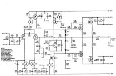
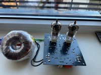
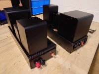
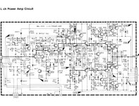
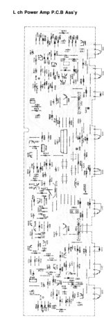
I've got a more complete write-up appearing in Bas Horneman's diy magazine, but wanted to put up some schematics for those who want to get a head start. It's easy to build, sounds great, and is a good answer for the common question, "Does anyone know a good 15W amp I can build...?"
First, the basic signal circuitry. Input stage is ECC81 (preferably JJ). Output stage is EL84 (again, JJ is a good choice).
I wanted to share this with you guys. Birch plywood has become very difficult to source (at least in the UK) and the price has doubled since this time last year. This is due to the fact a lot of Birch comes from Russia and well.. you know.
This is an alternative I actually like more than Birch plywood! It is alternating layers of Poplar (AKA Tulipwood) and Globulus (AKA Eucalyptus). The thing I really like here is the amazingly clean edge grain appearance. Birch ply, even high grade stuff, has lower quality cores than the faces and this leads to some dots and streaks on the edge grain.
This one is made by Garnica (Spanish) and distributed in the UK by James Lathem. They do one shown here with Maple faces (more expensive) and one with the Poplar as faces. I sanded and clear-coated. I'm not saying you should buy this exact one, but knowing such a thing exists is good.
The configuration is Raspberry Pi 4 + ALLO KALI Reclocker + Audiophonics I-SABRE Es9028Q2M DAC
The volume is very low. The issue is the same with Volumio and moOde.
Have you any idea?
Regards, Gábor
dmesg:
[ 5.672770] snd-rpi-i-sabre-q2m soc:sound: snd_soc_register_card() failed: -517
[ 5.689523] cfg80211: Loading compiled-in X.509 certificates for regulatory database
[ 5.741565] cfg80211: Loaded X.509 cert 'sforshee: 00b28ddf47aef9cea7'
[ 5.758132] cfg80211: loaded regulatory.db is malformed or signature is missing/invalid
[ 6.107685] brcmfmac: F1 signature read @0x18000000=0x15264345
[ 6.108921] snd-rpi-i-sabre-q2m soc:sound: snd_soc_register_card() failed: -517
[ 6.195965] brcmfmac: brcmf_fw_alloc_request: using brcm/brcmfmac43455-sdio for chip BCM4345/6
[ 6.201195] usbcore: registered new interface driver brcmfmac [ 6.299189] snd-rpi-i-sabre-q2m soc:sound: snd_soc_register_card() failed: -517
[ 6.514002] brcmfmac: brcmf_c_preinit_dcmds: Firmware: BCM4345/6 wl0: Nov 1 2021 00:37:25 version 7.45.241 (1a2f2fa CY) FWID 01-703fd60 [ 6.538018] snd-rpi-i-sabre-q2m soc:sound: Audiophonics Device ID : 20
[ 6.541812] snd-rpi-i-sabre-q2m soc:sound: Audiophonics API revision : 20
[ 6.721786] i-sabre-codec-i2c 1-0048: ASoC: error at snd_soc_component_update_bits on i-sabre-codec-i2c.1-0048 for register: [0x00000020] -121
[ 7.108284] 8021q: 802.1Q VLAN Support v1.8
[ 7.429501] brcmfmac: brcmf_cfg80211_set_power_mgmt: power save enabled
[ 7.628421] bcmgenet fd580000.ethernet: configuring instance for external RGMII (RX delay)
[ 7.631060] bcmgenet fd580000.ethernet eth0: Link is Down
[ 9.308799] hwmon hwmon1: Undervoltage detected!
[ 11.712934] bcmgenet fd580000.ethernet eth0: Link is Up - 1Gbps/Full - flow control off
[ 11.714438] IPv6: ADDRCONF(NETDEV_CHANGE): eth0: link becomes ready
[ 12.827162] IPv6: ADDRCONF(NETDEV_CHANGE): wlan0: link becomes ready
[ 14.787556] ICMPv6: process `dhcpcd' is using deprecated sysctl (syscall) net.ipv6.neigh.eth0.retrans_time - use net.ipv6.neigh.eth0.retrans_time_ms instead
[ 17.372677] hwmon hwmon1: Voltage normalised [ 25.199003] i-sabre-codec-i2c 1-0048: ASoC: error at snd_soc_component_update_bits on i-sabre-codec-i2c.1-0048 for register: [0x00000020] -121
[ 27.647484] brcmfmac: brcmf_cfg80211_set_power_mgmt: power save disabled
[ 29.468841] hwmon hwmon1: Undervoltage detected! [ 30.201826] i-sabre-codec-i2c 1-0048: ASoC: error at snd_soc_component_update_bits on i-sabre-codec-i2c.1-0048 for register: [0x00000020] -121
[ 33.500749] hwmon hwmon1: Voltage normalised
Hi all dose anyone have or know where i can get the plug from the valve panel that connects it to the main Avo unit part of the meter, for the Avo twin panel tube tester.
Wanting to model some driver combinations I decided to try WinISD since it seems popular. (I used to use LEAP and loved that thing but now...it would be just too much work to try and get that to run on some ancient hardware...).
I figured out how to enter new driver parameters and scale to absolute SPL. Yay me!
My next question is: how can I duplicate a driver entry? In other words I want to take an existing driver entry, duplicate it, and change a parameter like mass or BL, without re-typing all the stuff.
I maybe can't even find where the right driver file is...I can "see" something in File Explorer but can't duplicate and rename that raw file.
Can anyone help me. I have a problem with my AHT (American hybrid technology) phono stage. I am getting a reading of 16 volts from both outputs. I have replaced the6 op-amps but still the same 16 volts is read with the supplied voltage tester. Anyone’s help would be much appreciated. Thanks.
Thanks in advance to those who may respond. I'm putting an Adcom GFA-5400 in my theater setup as the fronts driving Thiel 3.5's with the bass module and I've adjusted the DC offset to nigh onto 0.0 and am in the process of tweaking the bias. I've upped it to 0.053+/- and the temp of the heat sink is about 42C. Nelson Pass in a post biased his by touch but he didn't state a preferred voltage. Has there been an accepted bias voltage maximum for this amp? As I'm sitting here, the v has gone to 0.055 and the temp to 44C. Does Bias tend to run away with increased temps?
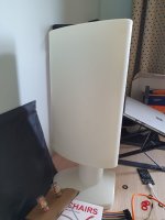
Just spotted this on facebook marketplace and figured people would find it interesting. A prototype speaker made for the world's fair. I'm not the seller or have any affiliation.
Hello friends,
I was thinking of making a spud test bed to serve as either preamp or headphone amp, where i can evaluate a lot of different tubes (most interested in DHT's) using a daughterboard, avoiding having to rebuild a new amp each time while also giving excellent performance.
I know its not exactly classical and a lot of people will raise there eyebrows and scoff at the lack of iron, but here are some design requirements:
-Should be able to run headphones with low distortion using even anemic DHT's
-Great performance into light loads (preamp duty)
-No iron, not as choke load or output (such as parafeed) - complicates things in many ways, not the least of which is that its hardly repeatable for others who wish to build, as everyone will find different iron, and doubles the BOM cost
-OTL
-Transparent representation of a certain tube (i.e, not having to have an amp with several stages, mixing and matching various input and output tubes for the amp to perform well, at which point sound depends on interplay of too many things, in addition to each stage bringings its own color, in theory also complicating the harmonic spectrum and so on)
-Run 24/7, for months on end
-No (global) feedback
Naturally a hybrid mu-follower (gyrator) fits the bill and sounds excellent and transparent. The output impedance is 1/gfs of bottom device in the gyrator which we can select for, and does not depend on the tube, which automatically opens a door for driving all sorts of loads. In addition it provides a high impedance load to the tube. Gain is nearly mu. PSRR is very high. A lot has been written on the topic already that can be found elsewhere, Ale Moglia's presentation is an excellent primer.
In addition I also wanted to add an optional buffer output stage, this one using OPA1656.
-Modern opamp like OPA1656 in unity gain, <2Vrms, is indistinguishable from a piece of wire (IMHO)
-Takes care of heavy lifting, provides even lower Zo, can use small high quality coupling capacitor instead of 50uf+ film chonkers
-Easy to implement (low component count, low cost)
-Now in addition to rolling tubes, you can also be a snob about rolling opamps, all in the same amp!
-Futureproofs it for use with 32R headphones, and enables use of anemic toobz with no issue
-Takes care of any possible slew rate issues, tube not wanting to run the HP cable capacitance, etc..
-Since this will be powered 24/7, i might also decide to run lower currents and be able to get away with it, in addition to essentially having the front end just be a preamp working into a very easy load, giving low distortion (remember these are not speakers where amp is almost negligible, HD650s are very revealing)
-Any other output stage i tried performed worse than just taking the output off the gyrator, while wasting a lot of power and requiring cooling solutions (i.e MOSFET source follower etc), so if we're gonna have anything at least make it not worse than gyrator alone.
-If we dont want to use it, we dont have to. Its just there as an option
For powering the opamp, the simplest solution seems to be a very low noise, very high PSRR LP5097-4.5 LDO. It will just about accept up to 6.5v input so i can take it from the filament heater, and OPA1656 will just about work with 4.5, so we squeeze through this hurdle. Since it will work rail to rail, means we can eek out 1.5Vrms, which is 107db on HD650's, about the loudness of a car horn, I dont think listen to half as loud.
First jumper JP2 just adds a high value film cap, used when driving headphones. Then the following selection jumper either goes out to output, or to the aformentioned opamp buffer. The opamp does have resistors for adjusting gain just in case (because it would be difficult to tack on later), but the jumper JP3 and JP4 turn it unity-gain. The R10 100k resistor is just so the amp is never unloaded, but if we select the opamp jumper it forms a voltage divider with R13, so that the input is on 1/2 the rail supply, since the supply is unipolar.
You might notice there's no toob, that's the whole daughterboard bit. There's a header J7 and J6 to hold a different board that will have the relevant bits (noval, octal, etc socket). Could make a number of those daughterboard depending on what you want to put on there, but i also made the daughterboards so you can jumper things around if necessary to match the pins. By default, it is pin pefect for ECC88 family of noval tubes, because there's a lot of tubes there you can just drop in with no finnicking.
Cathode biasing is using SiC diode, though you could just as well solder some LED's if you so prefer. Using the jumpers you can select the voltage, each step adding about 0.9V. There's one jumper extra at the top giving the ability to disable the SiC array alltogether, allowing either a resistor to be added in place, or to futureproof if i later decide to have biasing on one of the daughterboards.
On the bottom right there's also a selector for running either 6.3v heaters or 12.6v heater tubes on 6.3v, again selection jumper.
You might also notice JP19, used for when DHT tubes are installed, since the heater is the cathode, then you would unjumper JP17 and put the filament reg on pins 2 and 3 of JP13. The reason JP19 is is 2 way selectable is i dont know yet if it makes any difference to have the biasing on pin 8 or 1-7 (for tubes like 4P1L where it is common to "fold" the cathode for more even heating)
In the bottom left corner the 3 jumper ( JP14, JP15 and JP16) are to run tubes that have 2 triodes in the same envelope (like a lot of novals) in parallel. Since you're wearing out the tube anyway might as well make use of both. Again something to experiment with.
There's probably too many jumpers on this board but i hate when i wished i had put one when i hadnt, more than the other way around.. if there's ever a v2 a bunch of them could be dropped
It is relatively simple and nothing much to say, but since im the kind of person that would fall inside an open manhole i'd like a sanity check and any thoughts, any obvious fails or suggestions...
Philips n2400 Casette Deck
I only use this part of the circuit, I need to make a preamp can you help me?
Since the circuit is a cassette player circuit, I disabled its own preamp section (due to hum noise).As a result, output watt is reduced by approximately 60%.
Can you help me by making a circuit diagram?
I sometimes use this circuit, which I removed from its own circuit, as a tone control.
Raspberry running Ropieee mounted on a StationPi Pro
FifoPi Q7 mounted on the clean Side
MonitorPi Pro mounted on the dirty side of the FifoPi Q7
ProtoDac mounted on the clean side of the FifoPi Q7
StationPi Pro Raspberry side powered by a 5V linear PS
Jumper on J9 of the StationPi
FifoPi Q7 5V by LinearPi + UcConditioner
FifoPi Q7 3.3V by LinearPi + UcConditioner
Here is the troubleshooting that I have done so far:
1- I first have installed the Protodac on top of the Raspberry and good sound was comming out of it
2- I then installed the Raspberry on the StationPi and ProtoDac on the clean side of the StationPi and the sound was comming out good also
3- I then installed the FifoPi on the clean side of the StationPi with the MonitorPi and the ProtoDac on top. There is bit rate and all the data showing that the song is playing on the MonitorPi and both I2S and Lock led are green, but no sound from the ProtoDac anymore...
Anybody have an idea why there is no sound going thru the ProtoDac?
These were gently used in an MTM project that saw some casual listening for about 6 months. They were never pushed and performed fine. My father has since become a full-range enthusiast, and is moving on in that direction. $105/pair plus shipping.
I'm selling some mixed tubes. My tubetester is out of order, but those below have been tested with PS and compared to specifications, probably unused.
Located in Sweden. Shipping not included.
Does anyone have experience with https://cyberstore.ee/?
I placed an order more than a week ago and money has been withdrawn but I'm yet to receive shipping notifications and they're not responding to my emails asking for an update.
I have a vintage Sony STR-6045 amplifier that I managed to restore with the help of the wonderful users of this forum. There was one last thing to do on it: to reduce the dc offset on the left channel that was 95 mV. The task was fairly simple as it was involving replacing Q701 and Q702 with a matched pair of transistors. In the process, I managed to break the legs of other transistors (Q756 and Q703). Since they were old and noisy, I decided to change all those transistors type (4 2SA706) and (3 2SC1124) with Toshiba TTA004B and TTC004B.
Stupid me, I misread the pinout and created a good light show with my bulb tester.
Since then, I have re-soldered correctly the seven transistors and get no more light but I have lost the left channel. So far:
Q704 was damaged and I replaced it.
Tested D702 (a varistor?), it has the same resistance and voltage drop as the right channel.
Tested on board and out of the board a few transistors with diode tester function.
Tested RT701 (the variable resistor that is used to set the 25mV bias). Resistance does change when turning it but no more voltage on R721-722.
I have highlighted in yellow the voltages that are far from expectation. 30.7V at the emitter of Q757 being the one the most suspect, but I think the schematic is wrong since the right channel is working.
I am at lost as to what I could have missed. Would someone with experience understanding circuits could suggest what else to verify? Voltages in BLUE are actual and in RED are expected.
I am new to tube based guitar amps. I do have hifi tube amps, preamps, and headphone amps.
This Vox, a 2018 AC30S1 is new to me, but came used from online retailer/GC.
Anyways, I have a little bit of hum on the speaker, and according to my scope it is 120Hz.
I have 2 questions, as I am used to hifi tube amps being dead mostly quiet.
Is this part of the design of the amp?
Given a no/maybe to question #1, what should I troubleshoot?
Things I have checked/tried:
Tightened all transformer mounts and chassis grounding nuts. Input nut, switch nuts. (I didn't check all the pot nuts. Whoops)
Pull the 2 preamp tubes (2 x 12ax7)
one at a time (no audible change)
both at once (no audible change)
Pull all 4 el84s (hum is GONE)
Pull 1 el84 (hum is LESS)
Pull 1 pair of el84s (no audible change)
Tapped on the circuit board while hooked up to the scope (looking for dodgy connections); this didn't seem to have any effect on the scope output.
Changes in the Gain/Volume/Bass/Treble/Reverb controls do not affect the loudness of the hum.
I assume the full set of tubes are the original tubes. All read "China" no brand name.
What is the diagnosis? Is this normal for the amp design?
Not a lot of AC30s floating around last time I was at the local shop, so I don't have a lot of mental comparison points.
What else should I try before pulling boards/reflowing solder etc?
Hey everyone - getting close to having my cabinets finished (18" Bass / Mid-bass up to 388hz) in a 2 way system.
These are bandpass enclosures that GSG Audio custom cut for my woofers and application (MBM) with a single slot port.
They have incredible bracing - but I'm trying to decide on either polyfill (don't want lots of loose filling), or something like this
along the back wall behind the woofer:
A couple questions - I like the Acousta-Blue at first glance - easy to work with, neat, will look professional when applied.
Will it increase the apparent "cu ft" of the enclosure as polyfil will, or will it reduce it?
The AE Speakers link shows cu ft for mid-bass is 2-3 cf, and for bass is 4-8cf.
I have some playing around to do and testing, just wondering what everyone's opinions are.
System is a 2-way with a 22" Circular Horn mated to a 7" (5" VC) Compression Driver crossed at 388hz. Already ran the tests with REW and UMIK1 and 388 was the sweet spot for the compression driver and horn.
Now we are just waiting for the Acoustic Elegance woofers and finishing the bass / mid bass cabinets.
I decided to recap my amp, as it's 22 years old this year. I've removed all caps from the power supply board and now looking for the best replacement for the two large filter caps: 12000uF 63V 85'C.
I've found two good options that are in stock, but can't decide. I don't have the ripple current rating of the old caps and no idea how much is present in my amp which has 95 watts per channel into 8Ω in class AB mode and 25 watts in class A. Should I get the lower ESR cap (21 mOhms) with 6A ripple current rating or the slightly higher one (33.9 mOhms) with 8A? I would prefer the lower ESR one, but worried about ripple current. What would you recommend?
I built the classic 6v6 from Dynaco, I really liked the process and I'm learning a lot.
I was looking at several posts here in the forum about NFB or FB in general.
I read some articles from audionote, as well as from Japanese amp builders about the FB, and realized that they don't like it very much.
And that's where my curiosity comes in.
I read here, I don't remember where, that ultralinear OPTs are a kind of local FB, how true is that?
My query is:
I was doing some simulations in LTspice, with and without FB (the one in the schematic).
How accurate is this representation in LTspice in terms of reality?
Do my valves and transformers behave the same?
and if so, I leave you 2 tests that I did, one with FB and the other without FB.
What happens with the signal, is it what happens in reality?
I notice that without the FB, I turn up the volume of the amp and it seems like it is screaming in my face, it makes sense.
As I told you, I am learning from you all the time and I want to continue doing so.
I've done a lot of research on the forum and found many great threads around this question, but I still don't have a clear picture.
On my OB (really nude) with waveguided tweeter, I'd like to extend the dipole behaviour to the highs.
Few years ago on a similar setup I had the TPL-150, it was great really, airy, detailed, super sensitive and flexible for xo.
I only remember its vertical size being a little issue, at the time on MTM.
Sold everything when I moved, then restarted from scratch, for 2 years I was happy, I also had many other things to focus on the system.
Few months ago I went with Azura horns and faital CDs (for many reasons like added sensitivity for tube amp, flexibility, smooth dispersion of the JMLC, curiosity, and just beauty of the object).
But the itch is coming back, I need to find out what I'm missing with a real dipole up there in this room that is now much bigger (around 150m3).
So I'd like to test without breaking the bank, before I sell my pair of tw29bnwg and/or pair of Azuras, do you see anything that could fit the need for an acceptable price, like around 400eur for 4 tweeters or 2 AMTs?
I'd like to avoid selling the current ones as I'm sure I will regret for potential future projects, so many times I sold stuff and needed it later.
The TPLs would have the best dipole behavior, but are expensive (only the tpl-200 are available at TLHP).
I need either high sensitivity or good power handling to match current midrange
Small enough to be attached back to back, with or without a baffle (none right now).
Since I'm also planning to try a different mid range, I need some flexibility on the crossover, for probably a 2kHz high pass, active.
I thought about
finding a CD that I can open the back, but here I would have a discrepancy between front waveguide and back unguided.
Seas 27TFFNC or SBacoustics SB21SDCN, just not sure they can accept a low crossover, and seem limited on power.
smaller AMTs like the TPL-75 (back can be opened too) or SATORI AT60NC (don't know if can be opened), they are not that cheaper, and I might regret getting the big ones.
As always writing this helped me to clean my thoughts, it seems the SB29SDNC is a very good option, price/power/spl/size, except dispersion.
Or do you have any other idea?
Any details I forgot to help you propose something? Thx!
I am new to amplifier circuit design so please excuse my ignorance.
I noticed that some amplifier circuit have an output inductor parallel with a 8 to 10 ohm resistor. Could someone educate me as to the function of the inductor? What is the benefit of this part? For a high current amplifier driving a low impedence load, this part would seem to contribute considerable amout of DC resistance or cause the inductor to go into saturation. I may be mistaken about this saturation stuff since it is an air core inductor.
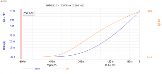
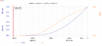
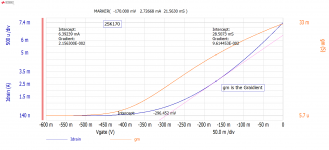
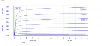
I have been playing with the software and hardware. Here are some of the plots of the JFET(s) I have been looking at.
First 2SK170. It is interesting that the RIP old K170 get all the talk, people are looking for a substitute.
In future post I will take a look distortion and noise; you know things that would make a JFET less attractive. For this look at distortion I am thinking of looking at the Common Source Amplifier.
See the attached K170 plots;
Vg ID transfer curve with gm curve with IDSS Marker
Vg ID transfer curve with gm curve with CutOff Marker
Vg ID transfer curve with gm curve with Marker and tangent line AKA gm.
Vd vs. Drain current with 0.1V Gate Volt steps.
The OP07 opamp has an BJT input. Typically this means a lower input impedance/resistance. Why is this not the case for the OP07? The reason I ask is that I was looking at the ProCo Rat schematic and was curious as to why it's typically listed as a 1M/500k input impedance circuit when it has an BJT opamp at its input stage.
I just got a free Panamax 5500-EX power conditioner that has a loud transformer buzz that starts up about 5 seconds after being plugged in. Is this something that can be easily and inexpensively repaired, or should I put it back where I found it? I've reached out to Panamax and they have no interest in servicing it; I'm waiting to hear back from them as to whether they will provide a schematic, but I'm not coding my breath.
I have an old Echo Layla 3G audio interface box that has a faulty headphone volume potentiometer. (makes crackle noises when I adjust the volume)
The problem is I'm not an audio engineer so I have difficulty trying to figure out what a suitable replacement might be for this part (see pic)
All I can ascertain is, it's a A10K - and there's 6 pins.
Google search reveals umpteen amount of these things in various form factors and I have no idea of what the technical differences between them are.
There is also what looks like a company logo on the part, but so far nothing has turned up with any clear indication as to who it might be..
If any kind souls familiar with this kind of thing could point me in the right direction that would be most marvelous as I plan to revive this box for a bit of fun.
Every time I buy resistors, I buy more than I need (Mouser bulk pricing usually means 10 cost less than ~4). So, I have a ton of extra resistors, in a wide variety of values. So far I haven't found a way of storing them that is a significant improvement from "toss them all in a bag". What do you guys do?
I am starting on a subwoofer project, the intended bandwidth is 25Hz to 200Hz. I have a couple of drivers with me and in a dilemma to choose the drivers.
I could use 6.5" x 4 drivers or a 12" car sub driver. Which is better and why?
Hello.
Been going through some transistors, and found theese, might be interesting for some of you
For example rare sanken 2sc2608, I believe I have mor and its counter parts.
And some high current Darlingtons.
And off course the mj21193g from on semi.
All are Nos except the sanken, they were briefly used in a prototype amp
Price?.
I'm now a full-time instrument maker, and thinking about how I allocate resources in 2020. I've been into DIY hifi since a teenager and want to resurrect two pet projects (1. Curve Tracer and 2. Audio Analyser) for my little company (Electron Plus) - thinking about which might have the most impact. Would love to hear feedback, what people are using and perhaps what's on their wishlist. The very basic specs as I left them before I got busy with sub-contract work:
Curve Tracer
PC connected
-200 to +200V collector supply
-20 to +20V / -200mA to +200mA step generator
<1uA to >5A
Dual channel option/version
2nd step generator/SMU option/version.
Audio Analyser
2channels
Fully floating input and fully floating output sections
>+20dBV outputs
Balanced ins and outs
48/96/192 and possibly 768KHz rates
I built working prototypes of both a few years back - but would probably refresh both designs (certainly restart the digital side of things). Probably got enough resource to do one of these projects only.
Intrigued by the LITEMOD 4HC design.
4 x 700 W @ 4 ohm
Appears to use only 2 x IRFH5020 mosfets per channel, PQFN 5X6 mm packs!
These are very capable devices: 200V, 43A, 55mOhm, but probably the most interesting feature is the body diode reverse recovery speed of trr = 45 nS!!
I would guess that there is a thick aluminium plate underneath the pcb (just under the fets) linking this to the back plate for thermal transfer, using vias in the PQFN 5X6 decal to link upper side with lower side.
Don't seem to use either snubber, flyback or series diodes. The lack of the diodes is of course because of the very high speed of the body diode.
Thinking of using IRFH5020 for my next project 😉
Does anyone have a picture of the underside of the board??
A service manual or schematic would of course also do 😉
In post #4 under https://www.diyaudio.com/community/threads/compensation-capacitor-cdom.105453/
I read this: The Cdom is the easy and very effective solution that virtually guarantees stable operation of a three stage "LIN" topology. But the downside is reputedly poor sound quality.
Try the non-inverting input for improved sound quality.
And use a very low capacitance transistor for VAS to reduce the current that gets sucked out of the LTP.
D. Self does not mentioned various alternatives - only the usual circuit topology for Cdom from collector to base of VAS transistor is described.
The only way I know to avoid Cdom at whole is the use of only one voltage gain stage - this means mostly a folded cascode (like realized in the AVM mono blocks and in the internal circuit of AD817 and AD797.
But this means in discrete versions less open loop gain.
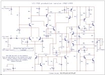
Some other approaches in power amps with two gain stages (i. e. LTP+VAS) is the attempt, to use the inverted input for Cdom (often with serial resistor) - check out the schematics in attachment three and four.
But I want to know exakt design rules for compensation steps at whole (without typical Cdom to avoid unwanted oscillation).
Thanks for any advice.
P.S.:
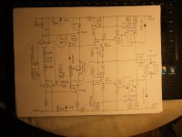
This desire arose after I receive a Horch 3.0s power amplifier that have unwanted oscillation - check out schematic with two voltage gain stages in the first attachment.
Here are to find some capacitors for compensation - partly at unusual places.
But at the usual place for Cdom in the VAS stage there are no capacitor to find (also not at the input for low pass function).
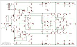
Most other amplifiers with similar topologies use there capacitors - go to the second attachment for an example (schematic of Leach amp).
Maybe an important fact to determine this exactly is the kind of output stage configuration (darlington emitter follower or CFP power output stage - go to the attachment five and six) so as the sequence of the serial inductor and the Boucherot cell (Zobel network) at the speaker output - go to the last attachment (Zobel network sometimes behind the inductor, sometimes in front of the inductor - i. e. just on the power amp output, which seems more plausible to me - go to https://www.diyaudio.com/community/...an-inductor-on-my-class-ab-amp-output.346796/
and read from post #7)
Ceramic capacitors are used in amplifiers for different applications
a bypass for electrolytic capacitors on voltage regulators
for low-pass filtering at the input and
for compensation to avoid unwanted oscillations (e. g. Cdom in the Vas stage, output load of VAS stage and bypass cap in parallel to the NFB resistor between output and input).
Aging does not have a destructive effect on the first both applications, but it may have a significant effect on the last application, because the resulting unwanted oscillation can destroy the transistors of the output buffer stage of a power amp.
This is because during this oscillation - as with an interrupt between the base of the Vbe multiplier transistor and pot for idle current - the maximum possible current that the mains transformer is capable of delivering flows through the power transistors of power output buffer.
This means that the power transistors will be destroyed instantly unless fast fuses provide protection.
There are to find a wide range of different versions for the ceramic caps at this place and from the first impression it is not possible to assume which dielectric material is used in the capacitor in question - thus there is no way to assess the effects resp regarding drift of critical parameters due aging after 10, 20, 30 and 40 years.
What kind of caps should one prefer in general for the aim of compensation in vintage power amplifiers in order to maintaining good RF behavior and also in order to maintaining good long-term stability - that is the main question for me in the moment.
Perhaps there are certain empirical values regarding this question - thank you very much for an information.
Currently I ask this in order to replace various ceramic caps of unknown kind in a power amp from Horch Elektroakustik model "3.0s" which provide unwanted oscillations around 2-3MHz on both channels - schematic and various images from PCB of this model under https://www.diyaudio.com/community/...d-3-0s-what-to-3-power-output-devices.379808/
and I have heard from an other owner, that several years ago the manufacturer itself in such cases always replace all the ceramic capacitors.
After a long search, numerous bumping threads, I finally got my Holy grail Alpine 7909 30th anniversary model, #291/300.
Someone had contacted me stating they had a mint in box unit. I paid $700 shipped which was fair. 🙂
Anyways, I havent installed it yet, so heres some pics.
Hi everyone,
since my music listening room has now given way to a children's room, I will be parting with some of my projects, which are either already assembled or not fully assembled.
Accordingly, I will describe what each offer includes.
I offer:
1 set of boards F5 (partly equipped) - since the dual “F5 mono bridged” design was planned, the additional boards are not equipped.
the set includes 2x Main Board and 2x Additional Boards
the 2 main boards are equipped with high-quality components (PRP resistors, ELNA Simic II, ...)
the additional boards unequipped (absolutely new, not yet used)
Power supply not yet set up, hand wiring was planned (without circuit board)
high-quality components available (Nichicon KG Super Through 10000uF / 63V + brackets, Vishay MKP1837 0.01uF 100V 1% 5mm, ClarityCap PX Series 250VDC Film Capacitor, Vishay Bridge Rectifiers 35 Amp 600 Volt, ....)
2 transformers Müller Rondo R3-0650-0006 - unused
(with shield winding Cu foil, magnetic shield in the housing; d=154mm, h=100mm)
Detailed list of the components used can be sent as a PDF
1 document - component overview, assembly instructions and notes
negotiable Price: 666€ (+ shipping)
Location: 1070 Vienna, Austria
Payment: cash payment or Paypal as a friend.
The boards and components can be sent or picked up personally from me.
Please ask if there are any questions left!
additional pictures can be sent upon request.
If interested please send me a PM.
regards,
Michael
As with all private sales. The right to guarantee or warranty is hereby excluded. No returns or exchanges possible.
Here is the detailed component list for the main boards:
Number of components is to be understood per main board.
The power MOSFETs (each matched octet available) are not yet soldered in.
and the component list for the power supply(s):
the following structure was originally intended for the two power supplies:
Hello all, have been lurking for a while and would love some help. Looking to turn a Quad 22 box into fully digital Roon endpoint and phono input!
Backstory
Currently in the process of rebuilding a couple of Quad Monoblock's and going back to basics as the units had failed when a previous owner 'upgraded' to EL34s. The Quad 22 was also in a very sorry state and instead of going analogue, want to turn this into Quad on the Outside, Raspberry HiFi running Roon on the inside.
Project Scope
My ecosystem is Roon and Tidal, and love the work @iancanada has done, where it looks like the STATIONPI PRO Raspberry Pi and HAT Boards Adapter Station will fit perfectly into the Quad 22 box. Want to try and keep the front panel as close to the original layout and am thinking:
Original Volume Control and Balance: Install Digital Volume Control and forget aboyt the balance.
Stereo/Mono Switches: Turn these into unit On/OFF. Yes have an aluminum CnC guys and engraver lined up.
Inputs Selectors: Use Position 1 and 2 on the input selector for DAC and Phone Input, which leaves me 2 spare.
Tone Controls: Remove and replace with round digital display for DAC info.
Help Needed
Would greatly appreciate thoughts or recommendations on how to best:
Phono: Get a quality phono input into the system and switching to the outputs to feed the Quad Monos?
Digital Volume: Recommended DAC that support 24/192 and can to the volume thing!
Displays: Any alternate ideas for the 4 round tone control cut outs, anyway of getting 4 displays running off a single Ropieee xl (I suspect not)
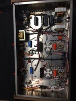
Hello all - I have a Kenwood DP-SG7 CD Player which won't power on.
I've opened it up and first port of call is a board with a transformer. I have 240v going in and on the ribbon cable that connect to the main board I am getting a reading of 13-14v. According to the service manual, if I am reading it correctly it should be more like 10v - see pin 1 below.
Is this in itself an issue?
I have also had a poke around the main board with a multimeter and I have found a FET which is giving an open circuit (beeping) when I test across Gate and Source in diode mode. The FET is still on the board though, does this indicate damage?
Also I have broken the ribbon cable connector that provides power to the main board - anyone know what type of connector this is:
Forgive me if this is a painfully rudimentary question. ELI5?
I keep my my system ultra simple. Small dedicated laptop. Win 11. Foobar installed. USB connected to DAC. DAC connected with RCA to vintage integrated amp. Ext harddrive backup.
I'm shopping for a used amp. Wondering if I can broaden my choices by simply using a PC plugin (software) pre-amp and bypassing the need for a hardware pre amp.
I can only find information on this online in discussions about music production. I find little information about consumer setup. But I'm sure it's just a matter of not knowing how to frame the question
I recently built a pair of Jericho horns using the attached drg. and fitted new DX4 drivers, the mids and highs are good, but the bass is very much lacking.
I built the same speakers 15 years ago with EX4 drivers and dont remember any issue with lack of bass.
I know very little about theoretical speaker design and based my choice on past experience, and have a few questions:
1. have i made a complete mis-match
2. if so can i improve the bass at all with eq filter or other means
3. what is a tried and tested combination for the DX4
so i was thinking of buying an old broken delta for spares for mine but then thought what if i could fix it myself but I'm having a hard time finding some some capacitors
this is what is needed i can find the resistors already of the mosfets and ill get some heatshrink for the legs but i cant find any film polystyrene caps rated for 22pf or 10pf, Digi key only goes down to 33pf, i can find 22pf on RS components but then when i look at the datasheet they go down to 25pf and i also don't trust buying from RS components.
I was reading a lot in this forum as my NAD 2600 has some issues and lot of good information here!
From one day to the other my NAD 2600 was stuck in protection, after reading in this forum, I started testing and found that one channel has a problem (I have checked the protection relays and they are working, nevertheless I ordered the upgraded relays). I found that left channel out I measure 94,5V on the other channel I have 0V. So I already unsoldered and identified transistor Q301 to be broken, also the resistor R339 was getting extremly hot… but there are probably mor parts broken. So is there another way than unsoldering all transistors to be able to check them?
After I disconnected the left channel power amp board, the amp seems to work with the right channel and the protection relays are switching after few seconds.
But what confuses me after testing all the voltage measurements from the service manual:
out should be ~0V but has 94,5V
the +- 95V rail is good and measurement +-94,5V
where it says 1,77V I can measure also 94,5V
I checked the 35V and 18V and they are good
—> so all the wrong Voltage on left channel probably due to some broken parts.
BUT: The +-72V rails from the service manual confuses me cause mine has +-57,6V! On both channels, but right channel is working with that voltage. So first I thought this is correct and maybe I habe a wrong service manual or different version. And I can measure the 57,6V already on the outs of the rectifier…
So is this incorrect or correct? is there another version which is not described in service manual? Is the rectifier or transformer broken or something else?
Would be glad if anybody could help with the voltage and maybe have a clue which other parts can be broken on the left channel.
I have a good sized heatsink and it is cooled by a fan - at this point using 38 volts with ra7's TDV. Biased at 2.6 A the heatsinks never get hot, not even close to hot. Nowhere near as hot as the SIT 1s would get which was HOT.
Would higher voltages allow the use of sightly less current - my scheme is to use closer to 55 volts? Even higher if possible. My capacitors are rated 100 volts and higher. I know the current would be greatly reduced just trying to figure out where to begin ... if at all.
Would the output power go up appreciably or would it be negligible?
Wish I could answer this for myself but I have no idea.
It is my first subwoof. Pretty basic, no dsp on the back panel so this must be done upstream of it. My Emotiva PT2 has a sub out with a variable low pass and it seems to work well. It also has a variable high pass on the pre out. I thought it might be hard to get it integrated with my speakers but so far, so good. It does stand up bass and cello nicely which is low enough for me.
I am need of help from the community. I am looking for the original T/H parameters for a VIFA M18SJZ4-04. It came out of a Sony SS-X70ED. Both are drivers are toast in each cabinet. I can normall come up with my own T/H but given they are damage, this is not possible. I have looked everywhere for the data sheet but it eludes me.
I’m looking to design a speaker specifically for sound healing frequencies.
Since the audio will not be heard, the volume won’t need to change, the only thing that needs to change is the frequency.
With the same excursion the driver could be driven by an electric motor that varies only in speed.
I’m looking for a designer to design this in CAD, I understand that this would require specialised knowledge and isn’t something normal. I will compensate you well if you have the skill set to do this!
If anyone knows any companies I should reach out to, knows any people that build drivers or have any ideas for the project please let me know!
I have a pair of relatively cheap 18" woofers. I have used one in a MEH as the bass part for quite a while with open back and I liked it. The new round MEH will not play as low, but I thought I might use these in a sort of bandpass sub, but with open back - like on the large MEH. The Hornresp record is attached. It needs some eq, but compared to a simple H baffle or a bass reflex box of the same dimensions, I get more efficiency and acoustic bandpass filtering as a bonus. It comes with the cost of boosting the low end need and needing more amplifier power and not much output below some 35 Hz. Amplifier is not a problem and it did not play lower in the MEH anyway, so this seems like a good compromise.
The plan is to have a simple 60 x 60 x 66 cm (OD) box serving as a stand for the round MEH. Would any other enclosure style in this volume have some advantages?
I have been looking at a few amplifier schematics recently and noticed two things that seem very common on class AB amps. one is a series inductor on the output, typically 1 or 1.2 uh, sometimes in parallel with a 200 ohm resistor, sometimes not.....and the second is an rc circuit to ground, ,not usual to see like .047 uf cap in series with a 10 ohm resistor to ground?
I’m thinking of creating over-engineered loudspeakers. They might be something such as the 3.5 ways floor-standing with 4 active drivers and 2 passive drivers, i.e.,
A 1” tweeter at the top of the front baffle
A 2” dome midrange below the tweeter
Two 10” woofers below the mid-dome in which the upper woofer is responsible for lower midrange and bass, and the lower woofer is for only bass
Two 10” passive radiators for deep bass at the bottom and on both sides of the cabinet, e.g., Acoustic Research AR-9/ AR-90 series.
If compared with a conventional 3-way system, will it be better than the 3-way? Assume all the crossover design is performed with the same techniques, by the same designer.
It’s just like comparing a multi-link suspension with a semi-trailing arm suspension.
I am selling my entire collection due to extreme hearing loss unfortunately. THD+N (Nick) on AK built me this 300b amp with attention to quality parts and professional build quality. I don't think you will disagree by looking at the pictures. Most of all this amp sound amazing!!! Built with Edcor iron and includes a pair of Shuguang 300B-98. NOS Sylvania 6SL7 GT tubes with 5U4G rectifier.
1850.00 OBO
Will ship at owner's expense.
Pay Pal F&F
Local pick up is always welcome in Clarksville TN
Thanks
Rich
Hello to everyone!
This is my first post here on this forum, and I hope there are going to be many more.
So right to the point:
I have an Adcom GFA-5500 power amp. One of the best I ever had. Sadly, it now looks like one of the main power capacitors have started leaking. So I'm looking for replacements.
I have found some high grade Mundorf ECaps with the same dimensions and the same terminal spacing, rated 22000uF, 100V. The originals are 18000uF.
Is it a bad idea to replace the originals with ones with higher rating? Or is it just good to have more reserves in the power supply. Will it stress other components?
I have a pair of Mission M33i floorstanders here that need replacement mid/bass drivers (amp malfunctioned and died).
The speakers didn't cost me anything and I don't want to spend much on a solution. The usage will be playing loud rock music and EDM in my workshop whilst me and the wife workout in our gym.
I can find the right size (hole spacing & cutout) easily enough.
My question is, the frequency response. The original drivers are 48Hz to 20,000Hz.
The replacements are likely to be ~35Hz to 8,000Hz.
My understanding (from a mate who may or may not know) is that for my intended use, I don't need frequency response much above 8,000Hz, recognising this is not an audiophile kind of setup at all. It just needs to be clear and loud. Overtones, harmonics, headroom etc, not so important (I think).
The specs of the originals can be found here: Mission M33i
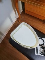
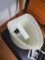
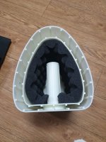
A little project I've been working on the past few months. I wanted some "ultimate" desktop speakers and with my limited workspace thought 3D printing would be a way to go about it. Still a WIP, but some first impressions...
The drivers are Markaudio Alpair 5.3. I used WinISD to create an EBS3 alignment which turned out to be 4.4 liters tuned to 58Hz. The cabinet design calls for a bit of EQ at the bottom end: 2.8dB at 74Hz with a Q of 0.707
Above is the "final" design. There are some aesthetic points and a few printing issues that I'm not 100% on board with, but overall I'm pleased with the way they turned out. Waiting for paint...
The design shown is a two piece (top and base) hollow printed design. Meaning I designed each part as a solid piece and the printing service I used removed extra material in order to have a hollow closed shell as opposed to the prototype which I designed as open shells to be printed solid and closed with covers (see attached). It saved a bit of money and hassle giving the solid design to the printing service and letting them adjust as needed. I intend to fill the hollows with epoxy resin at some point but it feels like a little bit of overkill for now. They are lined with eggcrate foam, connectors put in place, wired, and then the top is press fit onto the base.
Listening impressions:
Wow! For the first few hundred hours on the drivers I had them sitting on my piano bench in the prototype boxes to break in. One day I put on Harry Connick Jr's eponymous album and went about my business in another room. I kept catching myself thinking someone was playing my piano, haha!
Now that I've had these properly set up and gotten some good listening sessions in, I have to say that these are really exceptional for near field listening. The imaging and sound stage are crystal clear. I can close my eyes and see each cymbal strike, make out the exact separation between instruments in an orchestra, on some tracks from The Beta Band 3EPs for example I realized that notes can have different shapes. Bass is clean, clear, and precise and is more than competent to all but the lowest EDM notes. I've become addicted to playing Billie Eilish's "Billie Bossa Nova" and James Blake's "Limit To Your Love" as the bass presence is just amazing.
The only issue I have with them is that they only really come alive at a louder listening volume than I'd like. These are intended to be desktop speakers for somewhat background listening. They do sound very good at those listening levels, but get better as they get some more power.
When I get a quiet moment I'll do some measurements. I especially want to see before and after of the result of filling the hollows.
Hi, currently I'm using pair of floor standers with single fullrange driver MA Alpair 10p.
Due to ongoing furniture replacement I decided to make new bookshelf enclosures for the A10p and then add a single subwoofer for 2.1 system.
The space for the sub is next to the TV stove - the red box on the picture and it will be next to a entrance to another room.
The available space will be enough for a box with external dimensions (from the point of view) WxHxD 260x650x480 mm
The gross internal volume is 60L (2.11ft3)
What do you guys think is suitable for this scenario?
The sub out of my 2+1 amp is rated as 38W@8ohms and 75W@4ohms.
I'm not going to use it for parties just for normal listening and movies.
I'll very much appreciate driver suggestions!
Thanks!
Bought brand new long time ago have been using to power my klipsch center channel speaker in my home theater
Can watch for long period of time everything fine but many times in the middle of changing over from commercial to a TV show or in the middle of a movie where the sound stops the amp clips and cuts out completely and then immediately restarts. What in gods name is this?
I am planning to build a sound system utilizing Art Welter's Keystone subwoofer design, outfitted with one of the suggested B&C 18inch drivers. Question I had was whether to go with 4ohm or 8ohm driver variants. 4Ohm seemed preferable because it would allow for greater amplifier headroom for a given amplifier, but then I came across a thread somewhere that suggested something to the effect of: "All else equal, a higher impedance driver/amplifier combination will sound tighter." I interpreted this as: Running from the same amplifier, 100db from an 8ohm driver would tend to sound tighter than 100db from an otherwise-identical 4ohm driver.
This led me down a rabbit hole, where I uncovered the following: this thread here partially answered my question with respect to physical construction of drivers. Summarizing posts #8 and #11: "lower impedance means not only thicker wire and less turns, but more moving mass in the voice coil - therefore, voice coil movement becomes "sluggish", compared to different , lighter coils, high frequency response suffers, same with "sharpness", transient attack". I also found another thread that I can't re-find that suggested the following, focusing on the amplifier & current: With total output power being equal, the higher voltage into the 8ohm driver equates to the amplifier having a stronger 'grip' on the driver. The hose analogy was invoked - for the same amount of water, the 8ohm load sees a higher pressure and therefore should be more responsive. Ok, got it - higher impedance has sound quality advantages.
The downside then would be current draw & amplifier strain/headroom, since an 8ohm system will draw more current than a 4ohm system run at the same power/volume and also utilize more of an amplifier's maximum output power. (Edited to correct backwards math.)
I'm willing to believe that the sound quality difference is meaningful, and I will prioritize SQ to the extent possible, but I don't have an unlimited amplifier budget for amps to provide ample headroom for the 8ohm load.
So - which way to go? I'm sure some of you pro audio techs have wrestled with this before - is the extra ~3db of headroom (assuming roughly double the power at 4 ohm is available from a given amp model vs 8 ohm) worth the tradeoff?
Greetings.
Need to add some “tube goodness” to the newest generation of class D modules. I could use around 3-5 db of gain. My question is, HOW do I choose the tube circuit topology when there are many options?
Let's start with unbalanced version and 3-5 db of gain.
Be able to drive 20K input impedance, not add a lot of noise and most importantly, give me some tube sound.
Of course, I would prefer simplicity and real good sound! What am I missing with lets say, Decware zkit4, one tube, double triode, as simple as it gets? Why go further and what would other designs bring to the table?