Hi all,
I was reading a lot in this forum as my NAD 2600 has some issues and lot of good information here!
From one day to the other my NAD 2600 was stuck in protection, after reading in this forum, I started testing and found that one channel has a problem (I have checked the protection relays and they are working, nevertheless I ordered the upgraded relays). I found that left channel out I measure 94,5V on the other channel I have 0V. So I already unsoldered and identified transistor Q301 to be broken, also the resistor R339 was getting extremly hot… but there are probably mor parts broken. So is there another way than unsoldering all transistors to be able to check them?
After I disconnected the left channel power amp board, the amp seems to work with the right channel and the protection relays are switching after few seconds.
But what confuses me after testing all the voltage measurements from the service manual:
out should be ~0V but has 94,5V
the +- 95V rail is good and measurement +-94,5V
where it says 1,77V I can measure also 94,5V
I checked the 35V and 18V and they are good
—> so all the wrong Voltage on left channel probably due to some broken parts.
BUT: The +-72V rails from the service manual confuses me cause mine has +-57,6V! On both channels, but right channel is working with that voltage. So first I thought this is correct and maybe I habe a wrong service manual or different version. And I can measure the 57,6V already on the outs of the rectifier…
So is this incorrect or correct? is there another version which is not described in service manual? Is the rectifier or transformer broken or something else?
Would be glad if anybody could help with the voltage and maybe have a clue which other parts can be broken on the left channel.
Thanks a lot
Attachments
Are you sure? I do not think this will work…
e.g. I identified the broken 2SA1370 PNP transistor because when unsoldered beside the Base-Emitter and Base-Collector joints. I got a reading between emitter and collector as well on the DVM in diode function and it should not be connected, the other ones emitter and collector are isolating and no reading, but when they are soldered in the PCB I always get a reading between emitter and collector because it connects over the PCB even if transistor is ok, so when soldered I would not be able to identify the one which was broken, or do I get something wrong?
The same applies to the diodes, when soldered, none of my diodes is blocking one way, I have readings on the DVM in both polarities on every diode, when unsoldered, they correctly connects one direction and block the other…
But my bigger Problem is the question where the 56,7V come from and if there is a bigger Problem with that because the other channel is working with that voltage but service manual says 72V…?
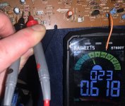
yeah I am using the diode test function so to correct me when I wrote I have a reading I meant measuring a voltage drop…
but for diodes, a correct one would mean measuring a voltage drop in one direction and no reading (or OL) in the other direction but when soldered, I can measure a voltage drop in both directions, I guess because of the wiring on the PCB.
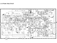
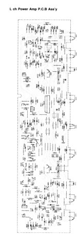
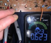
Attached are some pics of measuring and the schematic of the left channnel power amp PCB, also attached the service manual where you can see the complete schematics on page 15
problems is that output has 94,5V instead of 0V and instead of 72V mine has 56,7V (on both channels and working on the other one)
but for diodes, a correct one would mean measuring a voltage drop in one direction and no reading (or OL) in the other direction but when soldered, I can measure a voltage drop in both directions, I guess because of the wiring on the PCB.
Attached are some pics of measuring and the schematic of the left channnel power amp PCB, also attached the service manual where you can see the complete schematics on page 15
problems is that output has 94,5V instead of 0V and instead of 72V mine has 56,7V (on both channels and working on the other one)
Attachments
Are you using the meter "diode test" function with all the NAD power off, discharged, and its AC cord unplugged?
Normally, the DVM gives a beep if the diode is ok. The test uses the internal meter battery to activate the device's pn junction.
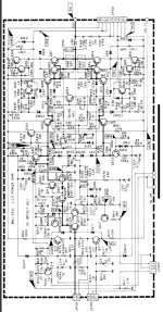
Unfortunately, that schematic is really bad.
Normally, the DVM gives a beep if the diode is ok. The test uses the internal meter battery to activate the device's pn junction.
Unfortunately, that schematic is really bad.
The 72V applies if the impedance switch is set to 8-16 (high). 60V is more like what you would see if the switch is set to 4-8 (normal). That part of your amp is probably ok.
To get 95V on the output there must be shorted transistors. Look for collector to emitter shorts on the output transistors and work back towards the input, checking collector to emitter of all transistors in the path. Start with Q317, Q313, Q309, Q305 and move towards the input.
To get 95V on the output there must be shorted transistors. Look for collector to emitter shorts on the output transistors and work back towards the input, checking collector to emitter of all transistors in the path. Start with Q317, Q313, Q309, Q305 and move towards the input.
Thanks a lot for all the info!
I tested all the transistors on the left channel and the only one which is broken is Q301 where e to c shorts…. have not found any other broken part and all diodes and resistors looking good. First I thought that resistor R369 is broken too because when measuring the Ohms when soldered this resistor shorts but should have 4,7Ohms, so I unsoldered it but when unsoldered the resistor measurement is correct with 4,7Ohms. When soldered this one shorts, but this is probably by circuit design, so I was wondering if I do need this resistor anyway, because of the short running the amp without this resistor must be the same I guess…
Anyway the broken transistor Q301 is a 2SA1370-E (attached is the datasheet). Those are not available anymore and Mouser electronics does not have a similar one with the same specifications. Does anybody know a replacement transistor for 2SA1370-E which is widely available preferably at Mouser??
Also the big Nichicon caps (want to replace them too) are not available anymore and specs from Mouser electronics are a little bit different, but I guess that using a 125V or 150V cap instead of the built in Nichicon 80V and 120V caps would also be ok as long as they fit in and have the correct value of 10mF. Or would a bigger cap with eg 12mF better?
Thank you for the help!
Attachments
L301 is in parallel with R369 which looks like a short circuit at DC. At high frequencies the L301 inductor impedance rises and the 4.7 Ohm resistor dominates the impedance. What you measured is normal. These parts are for amplifier stability.
It is too soon to be concerned with the big caps. In any case they are not precision parts and 12000uF is essentially not different than 10000uF.
It is too soon to be concerned with the big caps. In any case they are not precision parts and 12000uF is essentially not different than 10000uF.
- Home
- Amplifiers
- Solid State
- NAD 2600 Voltage measurement