Greetings.
Need to add some “tube goodness” to the newest generation of class D modules. I could use around 3-5 db of gain. My question is, HOW do I choose the tube circuit topology when there are many options?
Let's start with unbalanced version and 3-5 db of gain.
Be able to drive 20K input impedance, not add a lot of noise and most importantly, give me some tube sound.
There are so many options that I have found, just Broskie alone has at least 6 different ones.
Deware zkit4: https://www.decware.com/newsite/zkit4.htm
Allen Kimmel mu linestage
Broskie aikido, https://glass-ware.stores.yahoo.net/9pinccda.html
lampizator anode follower with 6n6p
Of course, I would prefer simplicity and real good sound! What am I missing with lets say, Decware zkit4, one tube, double triode, as simple as it gets? Why go further and what would other designs bring to the table?
thanks!
Last edited:
How much 2H crap to you want added to the signal?Let's start with unbalanced version and 3-5 db of gain.

Adding a tube input to a class D amp is a great idea. https://darklanternforowen.wordpress.com/2014/01/29/je-labs-linestage/
Many choices here...
Many choices here...
>How much 2H crap to you want added to the signal?
not much, I just like the sound of tubes without too much hassle! Is it H2 or other distortion -- no idea!
>Zin of the Class D amp
20K ohm
vilfort, what's that line stage?
But how much gain do you need for a modern class D amp? This line stage will give about 11V out for 1V in.View attachment 1140118
You can use a 6SN7 as the input stage. May have to play with the cathode resistor a bit. 1K seems a better choice.
Also, I'd make Rk 470R and Ra 24k to match the follower (6SN7 or 6CG7), Or make both load resistors 10k, the cathode 240R and use 6N1P, 6DJ8, or 6N6P.
Ya never quite figured out the db to voltage scale. My calculator says 1V in and 11V out is almost 21 dBV though.
Apparently 6 dBV is twice the voltage... (1V in 2V out)
You could build the above but change the plate load to 22k, add an input coupling cap, and add a 10k resistor under the cathode resistor. Less gain but less distortion, too.
Apparently 6 dBV is twice the voltage... (1V in 2V out)
You could build the above but change the plate load to 22k, add an input coupling cap, and add a 10k resistor under the cathode resistor. Less gain but less distortion, too.
That would be 20 log out / in. out / in is 2. Log of 2 to Base 10 is 0.301. So we get 20* 0.301 or a hair greater than 6 db.I need the line stage to add no more than 6 db gain.
Log of 11 is 1,0414. In that case out / in is 20*1.0414 or 20.83 db. In my mind the project is don't waste your time.
I had a Decware SV83 / EL84 vers amp here on the benh a couple of years ago.What am I missing with lets say, Decware zkit4
It was unable to make a real Watt of audio.
Some of my observations follow.
DIY Dec 30 21
SMPTE Official Definition
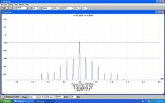
SMPTE intermodulation distortion test: The amplifier is fed a dual tone signal, 60Hz and 7kHz in a 4:1 ratio. The intermodulation distortion is the percentage of the residual RMS measured at the output (after filtering the test tones out) compared with the total RMS measured at the output.
Or how I do it with the PicoScope 3224 SA attached.
I ran a Decware clone on the test bench, the IMD was 9.74% while the output was 260 mWatts. The Decware amp always clipped at less than one Watt.
For a point of comparison I pulled an all 2V tube PP 33s amplifier off the shelf & ran the same test. At 820 mWatts the IMD was 2.67% . The PP 33 Amp clips at ~4.8 Watts.
To determine the internal resistance of the amplifier as seen by the load I measured the output voltage with & without the load connected. The internal resistance at One KHz looks like 5.09R, so the Damping Factor (DF) is 7.5/5.09 or ~1.47. About what we would expect from much biased pentodes with only 8 db NFB. But how much of that is the OPT?
Another set of similar measurements at the primary of the OPT shews a much better result. The internal resistance at that point looks like 3.39K, so DF is 6.7/3.39 or ~1.98. The amplifier could benefit from a better OPT.
Running the audio up slowly I found the 3H to be less than the 2H at ~10.5 KHz. But more at other levels. People building distortion cancelling circuits may not be getting what they expect!
Attachments
I would propose a ring-of-two topology similar to this:
https://www.angelfire.com/planet/funwithtransistors/images/FIG-5-06.gif
https://www.angelfire.com/planet/funwithtransistors/images/FIG-5-06.gif
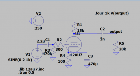
Something like what ive attached should work too, ECC82 or ECC88(would need to change some things for ECC88). It has less than 6dB of gain and seems to do well for a 20K load. Strong second harmonic for that tube sound too. Far from perfect(probably dont build this), just wanted to show that it can be done in a single tube
Attachments
I love the theory that if you stick a couple of valves (tubes) in front of an amp it will sound "better"
>No real bother of type or layout, just put them in and off to go!
Wait a minute! that's why I'm here, to get a recommendation on the type and layout! Are you recommending anything in particular?
You should look at the distortion profiles of each of those circuits you found and find the one that gives you the audible 2nd harmonic distortion you are looking for without the higher order harmonics that are not what you want to hear. Tube circuits can be modeled in LTSpice and the distortion can be estimated there without building anything. You can adjust the distortion of any of those circuits by changing the amount of feedback. To be audible I would think you would shoot for about 0.5% of 2nd order distortion. I spent several hours yesterday screening tweeters with the spectrum analyzer mode of Arta. After a while I found that I could screen them by listening to a 1000 Hz sinewave tone. I could hear the 2 kHz distortion tone clearly come through at about 0.5%. Of course I was looking for tweeters that were below that level.
About the H2 distortion:
look at this photo.

I am not sure that I am looking for H2 distortion as I have built and listened to diy h2 generator that I purchased right here on DIY audio store. It is H2 distortion and that is not the sound I’m looking!
On the other hand right next to it is sitting the Decware zkit4. Although it is too noisy, but at least it is the sound that I’m looking for. Therefore I raised this topic to learn if there are other tube and input stages that I should consider, where a lot of gain is not needed. Quiet, simple circuit with tube magic. NOT h2!
look at this photo.
I am not sure that I am looking for H2 distortion as I have built and listened to diy h2 generator that I purchased right here on DIY audio store. It is H2 distortion and that is not the sound I’m looking!
On the other hand right next to it is sitting the Decware zkit4. Although it is too noisy, but at least it is the sound that I’m looking for. Therefore I raised this topic to learn if there are other tube and input stages that I should consider, where a lot of gain is not needed. Quiet, simple circuit with tube magic. NOT h2!
Personally I would always prefer a DHT over an indirectly heated tube. When you talk of "tube sound" it's not the "warm" kind of sound you may be imagining, but instead a more transparent sound with more subtle tone to acoustic instruments. Addictive once you start using DHTs. Or in this case I'd suggest a simple circuit in filament bias with a 4P1L which has a low output impedance and can be used in a simple circuit with anode resistor. You strap it as a triode with G2 and G3 to the anode. It needs 25mA through it or even 30mA. Plenty of information on the long thread for 4P1L as a preamp. Filament bias would use a pair of V9 regulators from Rod Coleman at Lyrima, and he would give you all the circuit details you'd need.
- Home
- Amplifiers
- Tubes / Valves
- choosing a Tube input topology for Class D module