Hello to everyone!
This is my first post here on this forum, and I hope there are going to be many more.
So right to the point:
I have an Adcom GFA-5500 power amp. One of the best I ever had. Sadly, it now looks like one of the main power capacitors have started leaking. So I'm looking for replacements.
I have found some high grade Mundorf ECaps with the same dimensions and the same terminal spacing, rated 22000uF, 100V. The originals are 18000uF.
Is it a bad idea to replace the originals with ones with higher rating? Or is it just good to have more reserves in the power supply. Will it stress other components?
Thanks in advance
18kuF to 22kuF certainly won't be an issue. The tolerance on older electrolytic caps (when new) could be much much wider than you might ever imagine with historic worst case figures of -20% to +80% being seen in some cases. -/+20% is probably closer to the mark for something like your Adcom but the message is 'no problem'.
At the same time, I would also remove all screw connections, sockets, eyelets, plugs... and solder the strings directly. This will clean up and purify the sound enormously. Much less noise will be the result.
Aren't there also fat brass bars screwed in as ground? I would also remove them and replace them with cables. Will enormously concentrate and clean up the sound.
And the channel-separated power supplies I would still connect. That brings again really much in cleanliness and focus and spatiality.
Aren't there also fat brass bars screwed in as ground? I would also remove them and replace them with cables. Will enormously concentrate and clean up the sound.
And the channel-separated power supplies I would still connect. That brings again really much in cleanliness and focus and spatiality.
Thanks everyone! I love working on old amps, cant wait to order the capacitors and begin. Will see what I can do about all the connectors and if the cables can be soldered instead.
I have already replaced all the small caps with Elna Silmic II (as someone told me that N Pass suggest using Silmic II), and the sound difference was quite huge.
But, I have also started to experience some white noise in the tweeter when the amp is idle and there is no signal in. It's in both left and right tweeter, a little in the midrange. I use Infinity Kappa 9.2i
Some have an ide what the reason can be?
So the white noise problem actually comes from my preamp! I think. Because there is complete silence in the speakers without the preamp connected. There is a gain switch on the back, it was set to "high", I switched it to "low", and the noise is gone 😁
I have ordered the 4 big Mundorf ECaps, but I'm also considering replacing the 8 smaller ones that rate at 1000uF, 100V.
Would it be a good idea to replace them with for example 1500uf? Since I'm increasing the capacitance on the big ones. Mundorf Mlytic have ones that will fit.
And what are the 8 small caps in the power supply for anyway?
More is not always better. You need to understand how the power supply works and how the bridge rectifier only conducts for a short period of time each cycle.
The amp draws the same power from the supply whatever size cap you fit. If the cap is small the ripple is higher and the bridge rectifier conducts for longer per cycle to replenish that energy back to the caps. If the cap is large the conduction time (or more correctly angle) is less but the same energy still has to be put back.
The large cap causes very high peak currents in the bridge and in the wiring and most importantly in the transformer windings and this can cause the transformer to saturate and run hot and inefficiently.
I would stick to the original values give or take a reasonable margin.
Thanks Mooly! I'm only a hobby electrician 😅 understand that it is a completely different thing repairing an amplifier or replacing some part, than building one or understanding how it actually works!
But could you tell me, if I put in too large capacitors, how will this affect the sound? Besides the wirings and transformer going hot?
I will read more on this topic to understand it better
But could you tell me, if I put in too large capacitors, how will this affect the sound? Besides the wirings and transformer going hot?
I will read more on this topic to understand it better
The two IRFD210 MOSFETS on the input long-tail-pair of the GFA-5500 run pretty hot, and the solder connections get cracked from thermal cycling, which can cause noise. Perhaps it doesn't make the noise without the input terminated by the preamp...? Anyways, the fix is to re-flow the solder joints, and affix a small heatsink across the two of them with thermal epoxy. There is supposed to be a copper bar here already, but they often fall off. The heatsinks I use are meant for DIP-14 or DIP-16 packages, and it cools better than the stock copper bar.
While you're at it, the eight 1000uF/100V caps are problematic in this model. They cause weak bass when they go bad. Go for something 105C, meant for power supply duty not "Audio" grade.
While you're at it, the eight 1000uF/100V caps are problematic in this model. They cause weak bass when they go bad. Go for something 105C, meant for power supply duty not "Audio" grade.
The two IRFD210 MOSFETS on the input long-tail-pair of the GFA-5500 run pretty hot, and the solder connections get cracked from thermal cycling, which can cause noise. Perhaps it doesn't make the noise without the input terminated by the preamp...? Anyways, the fix is to re-flow the solder joints, and affix a small heatsink across the two of them with thermal epoxy. There is supposed to be a copper bar here already, but they often fall off. The heatsinks I use are meant for DIP-14 or DIP-16 packages, and it cools better than the stock copper bar.
Are those the Q1 and Q2 you are talking about? I will take a look at them.
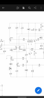
What is the correct way to adjust bias on this amplifier? In the service manual it says there should be measured ca 50mV between resistor R51 and R52, but I have read some place that this is incorrect! It's R50 and R51.
I have bought 4 low noise fans and will be mounting them on the heatsinks, two on each side. I also want to check the bias voltage, maybe setting it at bit higher to 60mV
There is a nice thread about this amp on avsforum. There a guy adjusted bias to 72mV without any problems
Attachments
And I'm thinking about putting in a softstart module.
https://www.atlhifi.com/shop/assemb...r-for-toroidal-transformers-assembled-tested/
Will thins work?
https://www.atlhifi.com/shop/assemb...r-for-toroidal-transformers-assembled-tested/
Will thins work?
Its actually the same differenceWhat is the correct way to adjust bias on this amplifier? In the service manual it says there should be measured ca 50mV between resistor R51 and R52, but I have read some place that this is incorrect! It's R50 and R51.
") Look at the circuit.
Look at the circuit.Ideally the current should be the same in each 0.68 ohm resistor (and you have ten of them) but in practice they may differ because of differences in the FET's.
50 mv between an upper 0.68 ohm and lower 0.68 means that I=V/R or 0.050/(0.68+0.68) = 37 milliamps is flowing in that pair. Its hard to immediately visualise but it doesn't matter which upper and lower set you use because they are all the same.
Set the bias with no load attached because a small DC offset can skew the result.
here is a nice thread about this amp on avsforum. There a guy adjusted bias to 72mV without any problems
More bias means more heat. Ultimately 50mv or 72mv is not high in the normal scheme of things but it is a definite consideration when you have all those parallel pairs of transistors. More isn't always better. Try it lower, a lot lower and see if you can honestly tell any difference in sound quality. Is it the same, worse, or better.
And I'm thinking about putting in a softstart module.
Does it need it? I would ask that question before adding one.
- Home
- Amplifiers
- Solid State
- Replacing power supply capacitors on Adcom GFA-5500