After more than 25 years of faithful service, it seemed that it might be time to redo my phono system. After all, I like to think that I've picked up a few tricks in the intervening years... The old system consisted of a VPI HW17-II, a Linn Ittok LVII tonearm, and a Troika cartridge. The Troika was a substitute for my previous cartridge, a Technics MM that I sorely miss. Given that the Troika cannot be retipped for anything less than a California mortgage payment, new MCs are priced like the fashion accessories that they are, and that the deck end of the phono system still worked reasonably, my attention focused toward upgrading the phono preamp and accommodating it to whatever cartridge I could dig up. That ended up being a vintage Technics MC, which was a nice find- I'm a big fan of Technics' high-end cartridges from the late '70s to mid-'80s. Second priority went to bringing the VPI up to a higher standard, but that's a story for a different time.
To celebrate the acquisition of the Technics, I decided to just chuck the old phono preamp and build a new one from scratch. The old one, a hybrid tube-FET cascode design, suffered from less-than-optimal noise and distortion, insane power supply sensitivity, and OK-not-great RIAA conformance, so the new one is designed to be better in those respects. And it turns out to be simpler than my old unit, which is a bonus.
This article will describe the preamp design and construction. An intermediate builder can duplicate this circuit in a point-to-point or perfboard build, but if you're an advanced builder, you've probably got your own way of doing things. Even if you don’t build this circuit, there are elements of the design process and result that you might find useful in considering your own designs. Beginners will probably want to use a PCB just to make sure that all is stable and quiet.
And, as usual, I will make some very unpopular design choices. Let’s go rile up the villagers!
Background
May I let you in on a little secret? All electronics are not created equal. Some parts are more critical and difficult than others. In any analog system (and music is originally and ultimately analog), there's some sort of input transducer, some sort of output transducer, and a bunch of wires and circuit elements in between. The difficult bits, and the most critical, are where the output of the electronics meets a transducer (speaker or headphones) and where a transducer meets the input of the electronics (mike amps, phono amps, tape amps). And (confession) most of the in-between is pretty trivial to do well; levels and bandwidths are generally well-defined, and there's not much “real-world” messiness.
The output part of the electronics chain has been well-handled by many fine power amp designs. In the tube world, the phono end has been much less successful. So-called classic preamps have terrible distortion and noise performance, poor drive capability, lousy headroom, and unmentionable overload recovery. Too many of the more recent designs are just lipstick on a pig; someone takes a circuit out of a tube manual, designed for the cheapest 1950s department store record consoles, slaps in a few designer caps, and proclaims it a wonder. Or a straightforward circuit is badly crippled by stuffing it full of fashion statements without regard to basic engineering. There are a few good ones out there, but not many.
I think we can do better. If you're going to do something as irrational as build a piece of tube gear, it's worth engineering it properly. And there are actually good, sound, rational reasons to use tubes for this application in the first place: headroom, overload recovery, and linearity.
Requirements
Accurate shooting requires a target. We will start by defining requirements:
1.
Low noise. The cartridge chosen has chillingly low output (0.2mV/5cm/s) making this a nontrivial point. It's unreasonable to expect 100dB signal-to-noise at these levels, but it would be nice to not add much to the cartridge’s intrinsic noise.
2.
Tight RIAA conformance. I don't think that 0.01dB absolute accuracy is necessary, but 0.2dB is a reasonable target. Channel-to-channel should be at least twice as close (if not better), and this conformance ought to be robust toward change in tube characteristics with age.
3.
Low distortion. This is where so-called classic phono amps really do a face-plant. One of the most popular "classics" drove a heavy capacitive load off the anode of a cathode degenerated 12AX7, a very high source impedance. And because of the resultant marginal gain and the economic constraints of a two tube design, the designer threw in a bit of positive feedback. The mediocre performance, then, comes as no surprise.
4.
Freedom from overload and blocking. This is another point where "classic" circuits fall flat. Let the cartridge mistrack or rattle slightly, whack the rock and lever that we laughingly call a "stylus and cantilever," and that 50kHz ding-dong resonance kicks the input stage in the groin- remember, magnetic cartridges are velocity sensitive, and though the mistrack is only momentary, that tip resonance is a lot of velocity. A minor disturbance (a swift kick) can turn into hundreds of milliseconds of overbias (rolling on the ground, gasping for breath).
5.
Capability of driving a 10k load and reasonable lengths of interconnect cables. The line stage with which this phono preamp is paired has a floating 10k input. No reason that a circuit should wuss out at this load just because it’s tubes.
6.
All-tube amplification. There are some decided engineering advantages to using tubes as the voltage amplification devices. At the top of the list are high linearity and overload immunity. My old unit was a hybrid using FETs in cascode with tubes (not unlike Allen Wright's excellent designs, though not claiming the same performance), and while it was good enough to live with for a quarter century, I still feel that its performance can be surpassed with an all-tube amplification lineup. Of course, I will still not hesitate to use semiconductors where they do best, i.e., for providing power, increasing power supply immunity, and controlling operating points- for constant voltages and constant currents, silicon is the way to go.
Design Requirement 1 is the toughest and most subtle one, and will drive some of the most painful design decisions.
A Short Digression on Noise
If you know your e
n from your i
n, you can pass over this section lightly.
There are basically two types of noise that electronic circuits can contribute, deterministic and random. Deterministic noise would include things like hums, buzzes, and rattles. These need to be fixed at the root-cause level, but they are fixable. Random noise is just that- random noise. Often white, sometimes pink, this is the “shhhhhhhh” background that pollutes many phono systems. Unfortunately, Nature sticks us with an irreducible minimum of noise from any device or source; the amount of noise voltage that a device contributes is always greater than or equal to
(1) V
n = √(4KTRΔf)
where R is the real part (resistive) of the source impedance, Δf is the bandwidth over which the voltage measurement is taken, K is Boltzmann’s constant, and T is the temperature or equivalent temperature. The derivation of this equation from first principles is shown in the Feynman Lectures on Physics, and is one of the most beautiful results in all of science. Admire it. Worship it. This equation will be with us until the end of the Universe because it is a fundamental consequence of the structure of matter.
Likewise, any random noise can be represented as an equivalent resistance, that is, for a random noise voltage of V measured over a range Δf, there is an equivalent ideal resistor R at a temperature T that is given by
(2) R
eq = V
2/(4KTΔf)
The takeaway: noise and resistance are correlated and can be inter-converted as equivalents. A random noise source can be expressed as an equivalent resistance and vice versa.
Don’t get too fat and happy. This theoretical value is the minimum noise that a real-world component can give. Real components add both random and systematic noise to the ideal resistance. This noise is often called (logically enough) “excess noise.” For example, if you measure the noise from carbon, metal film, and wirewound resistors of the same value, you’ll find that the wirewound resistor will have noise very close to ideal, the metal film will be slightly worse, and the carbon resistor to be a bit worse yet (sometimes a LOT worse). And to add to the worries, that excess noise is dependent on current… Well, we have our eyes open.
Because the source noise is random and the various sources of noise are uncorrelated, generators in series add as noise power rather than noise voltage, i.e., square root of the sum of the squared noise voltages. So for example, suppose one has three uncorrelated noise sources in series of 1mV, 0.5mV, and 0.1mV. The total equivalent noise voltage is then √(1
2 + 0.5
2 + 0.1
2) = 1.12mV. It’s notable and convenient that the noise power addition does make the largest voltage noise source overwhelmingly dominant, hence one doesn‘t need to do terribly precise calculations to get a good estimate of noise in complex circuits- simplifications will help.
A nice little calculational shortcut: if we plug room temperature and a 20k bandwidth into the noise equations, we can express the noise voltage-resistance relation as
(3) V
n = 1.8 x 10
-8 √R
Or
(4) R = V
n2 (3.1x 10
17)
And because of the RIAA equalization, any pre-equalization noise is reduced by the downward slope of the transfer function. The math is handled very nicely in a National Semiconductor application manual (Audio Radio 1980, Appendix), but the bottom line is that for a white noise source (characteristic of resistors), the effective bandwidth is reduced from 20kHz to 120Hz. So since V is proportional to the square root of bandwidth,
(5) VRIAA = V
n √(120/20k) = 1.4 x 10
-9 √R
This approximation is surprisingly accurate.
So a noise source can be expressed as an equivalent resistance R or as a generator voltage V
n. There’s one more little twist- sometimes, noise is expressed as “noise voltage density,” usually symbolized by e
n. Usually given in units of voltage per square root Hertz, it’s a way of comparing noise sources without putting bandwidth into the equation. For example, an ideal 1k resistor will (by equation 3) have a noise voltage from 20Hz-20kHz of 5.7nV. Another way to characterize the noise is to use equation 2, and rearrange:
(6) e
n = V/(√Δf) = √(4KTR)
Using this formulation, the 1k resistor is said to have a noise density of 4.1nV/√Hz. One can multiply this value by the bandwidth to get a noise voltage. Using voltage noise density is useful for situations where the noise source is not a simple resistance and where the noise voltage density changes with frequency.
As an interesting exercise, we will compute the signal to noise of the cartridge itself, just to see how quiet the preamp needs to be in order that it does not add any significant noise. The cartridge resistance is 15R. Plugging that value into equation 1, we find that the cartridge has 72nV of thermal noise at room temperature over the usual 20Hz-20kHz audio bandwidth. The cartridge’s nominal output is 0.2mV. Doing a quick decibel check, signal to noise works out to -69dB. Remember that number, it will come up again.
*
Overall Topology
There are several approaches to low noise tube RIAA stages. One is the classic feedback circuit popularized by Dynaco, Marantz, and Audio Research. These circuits are… not great. The limited open loop gain means that RIAA conformance changes with tube aging or replacement, the first stage will require a noisy cathode resistor, and the output stage will drive a heavily capacitive load at high frequencies. Distortion rises at the low end, where the feedback isn’t very effective, and at the high end, where the capacitive load reduces the available open loop gain and in some cases causes slewing distortion. What was it that Morgan Jones said about classic phono stages…?
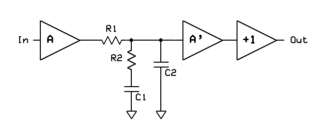
Since we’re working with tubes, which are intrinsically more linear devices than transistors and can swing considerably more voltage, there’s no reason not to use a passive equalization scheme. One quite simple implementation is the topology shown in Figure 1. In this topology, a so-called “all-in-one” RIAA equalization network is sandwiched between two gain stages. A buffer isolates the second gain stage from the load (interconnects and whatever you’re using for a line preamplifier). The all-in-one RIAA network achieves the 3180us, 318us, and 75us time constants in the RIAA standard; working equations for this circuit are given in a useful paper by Lipshitz, or you can use a handy-dandy on-line calculator which may be found at
KAB ELECTRO ACOUSTICS to get the values of R1, R2, C1, and C2.
A common variation of this topology is splitting the 75us time constant off from the other two, then sandwiching it between the second gain stage and the buffer. In many cases, this can help with noise and headroom, but I have a sneaking suspicion that it’s done that way just to make the math easy. No matter, if the first stage has LOTS of gain and reasonably low source impedance, the all-in-one network will carry no noise disadvantage and will certainly improve the headroom of the second gain stage.
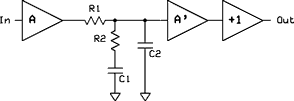
Figure 1. Passive EQ RIAA stage topology
Let’s estimate the gain we’ll need overall, taking into account the RIAA equalization. At 1kHz, RIAA is down 20dB from 50Hz. So if we want (nominally) 0.5-1V out from the phono preamp at 0.2mV and 1kHz, we’ll need about 85-90 dB of gain (taking into account the loss from RIAA). No wonder so many circuits fall flat! Now, because the 0.2mV spec is at 5cm/s groove velocity and many records have modulation higher than that, we can relax the gain a few dB and make it up in the line stage, if necessary.
First Stage
OK, I'll begin by turning off half my readers- the design will use an input transformer. This "impure" approach carries too many advantages to ignore, including nearly noise-free gain, galvanic isolation, and the opportunity to run the phono cartridge in a balanced mode without doubling the tube count. Running balanced inputs is an amazingly powerful technique to reject common-mode noise and is common studio practice for low-level mike signals. This does require a nonstandard cable, but some twisted pairs and shields never hurt anyone.
The question begged is, “Can I run an MC in directly?” Mmmm, perhaps, but at a noise penalty. Let’s say that you choose a particularly quiet specimen of tube; the very best have input-referred equivalent noise resistances in the 60-100R range. Cherry pick to get a 60R. Compared to the cartridge thermal resistance (15R), that represents a 7dB degradation of the already-marginal signal-to-noise ratio.
Massive paralleling of input tubes might prove efficacious, at a stunning penalty. Four tubes in parallel will drop the equivalent resistance to 15R, reducing the degradation to 3dB, which is still not quite there. Transformer starting to look better?
Things get worse: to get that low noise out of a tube, the transconductance will be quite high, and high transconductance means oscillation is but a moment away. The solution is generally grid-stopper resistors, but they have to be 100R-1k before doing any good, providing yet another noise source, one big enough to swamp the tube’s noise. Maybe you can wave the magic ferrite beads on the grid leads and keep things stable (I can’t). But that just takes us back to the tube noise problem. Nope, if we want tubes, we want MC, and we want quiet, we need a transformer.
Once we have crossed that Rubicon, we find that the transformer brings some intrinsic advantages of its own. One advantage that do-it-yourselfers have over appliance operators is the ability to use non-standard interfaces if that will get the job done. We can design and construct for performance and not worry about some strange item that might get plugged into either end. This can pay dividends if we consider the phono cartridge, arm, cable, and preamp as a system instead of worrying that each part be universal. Out in the Real World, where billions are made or lost depending on the engineering, balanced circuits are de rigueur for transporting low level signals from Point A to Point B. So where do audiophiles use them? Why, between preamp and power amp, where signals are large and hum is easy to prevent. And high enders love doing it inside preamps, where there’s shielding, short wire runs, and controlled grounding. The weak link, the cartridge to preamp transfer of microvolts of precious signal is of necessity outside and exposed to the cruel world. Yet it is almost invariably done single ended, making a mockery of all further effort. It becomes doubly incredible when one considers that a cartridge (the odd Decca excepted) is not inherently single-ended; it can have both ends float just as well as it can have a leg staked to the ground.
The phono cartridge unquestionably needs to be run balanced. The signals are tiny, the opportunities for hum and noise pickup are huge. As a practical matter, that involves changing two hunks of wire and designing a phono stage with a balanced input. The first hunk of wire is the tonearm wiring. In a many cases, it might be thin, twisted wire, which would be ideal for balanced connection. If not, the intrepid constructor will then need to replace the arm wiring. Looking at what that would involve for my rare Linn arm, I decided that I was not intrepid, and refused to take the arm apart to check the wiring. But please do as I say, not as I do. As it happens, the short length of uncontrolled wiring in the arm didn’t cause me any undue noise problems, but every listening room is different.
The second hunk of wire is the tonearm-to-preamp cable. This is a critical hunk, since signals are small and noise lurks around every corner. One excellent suggestion from Morgan Jones is to sheath silver wire in Teflon sleeve, twist it, then slip a shield braid over the whole shebang. One of these days, I’ll do that, at least if I win the lottery and get over my fear of triboelectricity. In the meantime, I picked up a Good Trick, and found that some shielded CAT5 cable worked well. That stuff is perfect, several sets of twisted pairs, good quality wire and insulation. The pairs can be paralleled to reduce the cable resistance. And I can spend the difference between that and the silver/Teflon approach on beer and lottery tickets.
Once that balanced signal is delivered to the preamp’s input, the last remaining link is the Common Mode Rejection Ratio (CMRR) of the input. In order to do any good, a balanced signal needs a balanced input on the preamp. That input ought to have as high a common mode rejection as possible. The classic single-ended tube input will contribute nothing. A balanced, differential input will be better, but doubles the input stage noise. The transformer still seems to be our best choice.
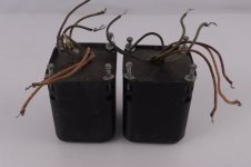
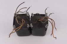
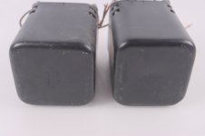
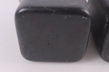
My old preamp used vintage Peerless/Altec 4722 mike transformers, which gave a very healthy 1:32 stepup. Unfortunately, this came with a bandwidth penalty because of the interaction of the secondary with its own capacitance and the input capacitance of the first stage. Thus my previously-mentioned Hobson's choice of a FET cascode, since first stage input capacitance for any high mu triode is too high for this transformer to handle without some impressive ringing of its own, right around where the cartridge is misbehaving the same way. That's not good.
Better transformers are available, and one excellent choice is the 1:10 Sowter 8055X, which was designed to have excellent input balance. The big disadvantage for the American builder is the price - after bending over for the unfavorable dollar/pound exchange rate, then paying shipping and duty, the Jensen equivalents start looking much better. Serendipitously, a friend of mine in the process of moving ran across a spare pair of the Sowters, which he sold to me for a bargain price.
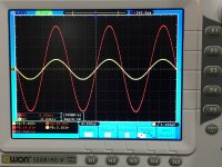
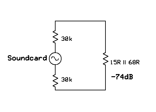
The Sowters seem much happier with capacitive loads than the Peerless units, and on the test bench, I found that from a source impedance of 15R driving the primary, a 6k8 secondary load resistor paralleled with 200pF across the secondary gave me rather beautiful square waves, free of ringing, and with a 4us rise time. That gives me quite a bit of flexibility as regards input stage capacitance- the FET can be dispensed with, and I don't need to suffer the disadvantages of cascodes (like their essentially zero power supply rejection). And the common-mode rejection was measured to be in excess of 100dB at 60Hz. All right! To make things even nicer, the secondary resistance (which determines the noise contribution from the transformer) is quite a bit lower than the competition- about 100R compared to nearly 1k in the Jensen 1:10 step-ups. This results in about a dB of lower noise, but every dB counts, doesn’t it? The nifty little attenuator I built for transformer testing is shown in Figure 2. It’s driven from the balanced output of my M-Audio Audiophile 192 soundcard, knocks down the signal level 74dB to avoid stunning the transformer, and has close to 15R source impedance like the cartridge. If you’re using a different cartridge (likely) or a different transformer, you can transform the values I used accordingly.
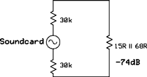
Figure 2. Attenuator for transformer tests
The 6k8 load does knock down the cartridge's output a bit, about -1.5dB to 0.15mV, but the signal to noise degrades less than that since the effective Thevenin resistance of the input system also drops from 1k6 to 1k3. But the loading still costs us a decibel of S/N.
With the transformer present and accounted for, the next most critical decision is the nature of the active part of the first stage. If we don't get it right here, we won't be able to recover later. And a good choice at this point will ease the overall design. The basic requirements here are low noise, low noise, and low noise. Secondarily, we would wish the highest gain possible- the input transformer has been kind enough to give us 20dB and we wouldn't want to let it down. We also recognize that the necessary RIAA equalization will knock down the level at 1kHz by about 20dB, so we're starting out on the wrong end of the lever. Every bit of gain will help.
The cartridge has a source resistance of 15R. This is transformed up by a factor of 100 to 1k5 by the 1:10 ratio of the input transformer. The input tube then should have an equivalent noise resistance that’s low compared to 1k5 so as not to add significant noise. It should also have a mu as high as possible to get the still-tiny signal out of the muck. That turns out to be 70-100 for practical triodes. One can get higher gain from a cascode, but an all-tube cascade that’s linear and stable is not a trivial exercise; worse yet, cascodes are superb at passing along every last bit of power supply noise, making the design exercise in ultra-low noise supplies a complex one. I think we can do as well with a classic grounded cathode triode input stage- not tricky, not glamorous, but it works.
A popular tube for this position is the 12AX7/ECC83. That can be a decent choice but requires quite a bit of design thought because of the high plate resistance (60-80k). If the passive RIAA build-out resistor isn’t large compared to the tube’s source resistance, the RIAA conformance will be dependent on the tube- not a good thing as tubes warm up, age, and change. A large build-out resistor means noise. Also not good. The 12AX7 often gets a bad rap for linearity, but the reality is that, with a very high plate load resistance (or better yet, a CCS), it has stunningly good linearity. But it does need that high plate load. Even with CCS loading, at high frequencies, the tube’s effective plate load becomes the RIAA build-out resistor, one more reason that the resistor has to be large and noisy.
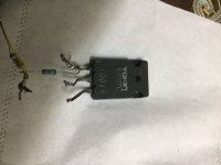
One other tube traditionally used in the first hole is the 417A/5842. This tube has a very low plate resistance (1k6) and high transconductance (25mA/V), but the mu is marginal (43). If only we could combine the low plate resistance of the 5842 with the high mu of the 12AX7…
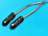
And of course, we can. The D3a is a European pentode that has become much better known in the past several years. It’s easily available, not terribly expensive ($10 is average), and can be connected in triode mode to give us a tube that’s ideal for this application. Mu in triode connection is 73 (not quite as good as a 12AX7, but 4.6dB better than a 5842), plate resistance is slightly over 2k, and the transconductance is an impressive 35mA/V. Equivalent noise resistance is 65-100R, certainly well below the 1k5 transformed source noise. It is slightly tricky to use- the high transconductance means that layout is critical and stopper resistors must be used to prevent oscillation. And there’s a lot of unit-to-unit variation, so it’s worth getting extras and doing some selection.
For the grid-stopper, I found that 100R kept things calm. And the noise contribution (compared to the 1k5 resistance of the transformed cartridge) is negligible.
Let’s choose the operating point. Looking at the D3a datasheet, we see that both plate resistance and mu vary rather steeply with current at low currents. By 20mA, they are beginning to level off, so let’s use that as a starting point. That leaves plate voltage and grid-cathode bias as the remaining interdependent variables. The bias voltage will determine the overload characteristics of the stage, so we want that to be high. But that also forces the plate voltage to be high and threatens excessive dissipation. For reasons that will soon be clear, 1.2V grid-to-cathode will work well. This results in about 140V on the plate- at 20mA, that’s a bit under 3W dissipation, so the tube is run well under its 4.5W limit and should be reliable.
Overload at the grid will probably start about 1V peak, or 0.7VRMS. Will that be sufficient? The cartridge has a 0.2mVRMS nominal output at 5cm/s. That ends up 1.5mV at the grid. Mistracking, dirt, and other vicissitudes of the LP Life will whack the stylus like little hammers, which is a lovely way to excite the high Q ultrasonic resonances to which all MCs succumb. The cartridge is a velocity transducer, so the high frequencies generate proportionately higher voltages. It’s not unreasonable to want at least 20dB of headroom above that. With our chosen operating points, we have 53dB before any input problems. I think that will do.
Now the question of bias method. Cathode bias using a resistor is a common method. But it carries the penalty of reduced gain and increased effective plate resistance. Worse, the cathode resistor contributes its own noise- the cathode is, after all, an input terminal. Bypassing can help, but requires a large cap, almost certainly an electrolytic. That can’t be good. And finally, although it’s unlikely this stage will overload, bypassed cathode resistors turn brief overloads into severe and clearly audible “choking” of a stage by extending the recovery time.
Another solution is battery bias. This is quite a good one, but I just don’t trust the stability and reliability of batteries, especially wrapped up in hot boxes full of glowing tubes.
My favorite solution, as anyone who has seen my earlier projects will know, is LED bias. The origins of this clever idea are obscure (I first saw it in the late ‘70s, proposed by Ike Eisenson), but it works like a charm. Forward biased LEDs have low dynamic impedance, low noise, high bandwidth, and provide essentially instantaneous recovery from overloads. They’re also nice troubleshooting devices- an LED that’s lit means the tube is conducting. The dynamic resistance is a function of current, so the magnitude of that and its effect needs to be considered in the design. The noise of the IR LED was too low for me to measure, probably somewhere around the Johnson noise of its dynamic impedance; even if the equivalent noise resistance were ten times the dynamic impedance, it would be negligible.
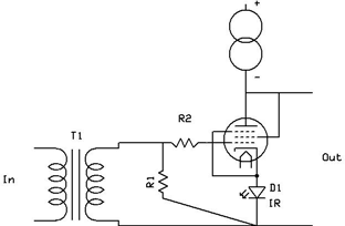
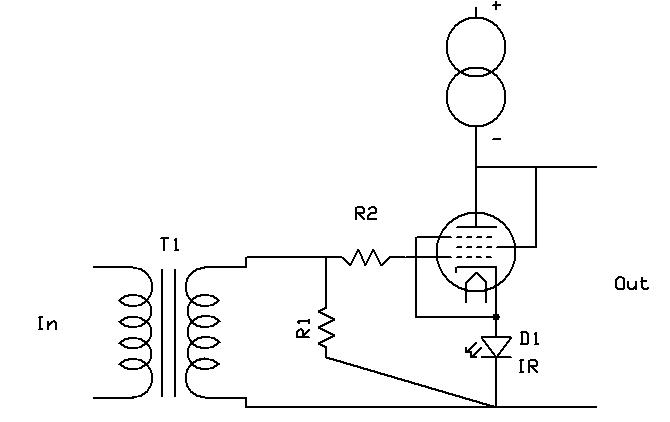
Figure 3. First stage topology
OK, we have our 1.2V bias, we’re running 20mA through it, we know from the datasheet that the plate voltage is going to be 140V, the last bit is the plate load. We can determine a good one by putting a dot on the D3a plate curves and pivoting a ruler around to find a good load line. But the most linear of all is a perfectly horizontal line, that is, a constant current. Constant current also maximizes the gain to near mu.
Constant current sources as plate loads bring some other advantages to the party. Constant current means that the variation in LED dynamic impedance with signal can be safely ignored. The plate voltage is automatically adjusted tube to tube and as tubes age to maintain the correct operating point. And power supply rejection increases dramatically- the CCS acts like an enormous (100M or more) series resistance, and that resistance forms a voltage divider with the tube’s plate resistance. So any noise from the CCS or the power supply rail is knocked down another 80-90dB or more.
The best bang-for-buck CCS also happens to have exceptionally high performance. The DN2540 depletion mode MOSFET is perfectly suited to make a simple cascode CCS with output impedances north of 100M and exceptionally low noise (14pA/√Hz, an insanely minuscule amount when multiplied and integrated with the D3a’s low plate resistance). So our basic gain block will look like the circuit in Figure 3.
We will check the input capacitance. The gain of the stage will be about 73. The grid to cathode capacitance is 7pF, the grid to plate capacitance is 2.7. Plugging gain and the latter capacitance into the Miller equation, then adding in the former capacitance and another 5pF for strays, we end up with about 210pF. Say, wasn’t that what we wanted to load the input transformer’s secondary? Hmmmm, quite a coincidence…
This exegesis on the first stage may seem overly long, but it’s the single most critical part of the design- anything wrong here will be faithfully passed down the chain and can’t be fixed.
Let’s see where we are: the input-referred equivalent resistance of the tube is 65R. Source resistance of the transformed cartridge plus transformer secondary resistance plus grid stopper is 1k5 + 100R + 100R = 65R = 1R765. From equation 1, this is equivalent to 0.76uV. Our 0.2mV signal has been transformed to a 1.5mV signal by the transformer, so our signal to noise is -68 dB. Remembering that the cartridge’s thermal noise limits the maximum obtainable signal to noise to -69dB, we’ve gotten through the first stage relatively unscathed! Our signal is now approximately 0.15mV * 10 * 73 = 113mV, which is well out of the muck and something we can deal with. At that swing, the distortion from the D3a drops to below any reasonable measurement limit. In the spirit of democracy, let’s move on and equalize!
The EQ Network
This is the easiest part. Once we make one basic decision, it’s all rote calculation. The D3a stage has an output impedance of about 2k2 or so. Referring back to Figure 1, R1 comprises the source impedance of the D3a. Adding a series resistance will make the loading on the tube kinder, limit the drift of EQ accuracy with tube aging, and provide a convenient way to trim the network for accuracy. If we choose the value of R1 to be about 10 times the plate resistance, the gain will hardly budge and neither will the distortion. A 10% drift in the tube’s plate resistance will only cause a 1% change in the effective value of R1. The only penalty is slightly more noise. We can take comfort in the observation that many well-regarded designs use much bigger (and hence noisier) resistors in this position, but we’ll quantify that momentarily. By jiggering things around a bit, we can try to get as many standard values as possible. With the total R1 (resistor plus tube) of 21k7, C1 works out to be 0u1, R2 to be 3k15, and C2 to be 33n5. Given the tube’s output resistance, R1 will be somewhere north of 18k- I used a 20k, then used large resistors (>200k) in parallel to trim it. Likewise, R2 can be 3k3, with a large resistor (100k) in parallel to trim it into place. C2 came very close to 33n, a standard value, and could also be trimmed with a few hundred pF.

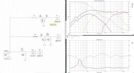
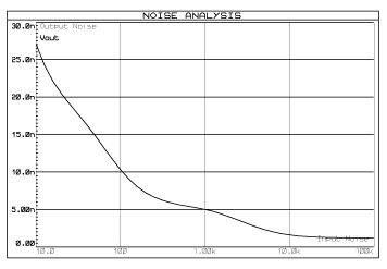
Figure 4. Thermal noise from RIAA network
Now, what will be the noise contribution of this network? In this case, because of the shunting effect of the various capacitors, the voltage noise density will have a strong frequency dependence; it won’t be just be R1, it will be somewhat smaller because of the parallel reactances of C1 and C2. There’s at least two ways to handle the complication of the shunt caps. If you’re a He Man, you’ll follow the procedure that National Semiconductor outlined in the early versions of their Audio and Radio Applications handbook. This involves dividing up the audio spectrum into frequency bands, computing noise from each band, then power summing the contributions.
The wuss way (but far more accurate) is to send a schematic to someone who can actually use SPICE (I am totally inept) and have the computer run a much more accurate simulation. Being a wuss, I pawned the task off onto a Dutch elf and ended up getting the graph of Figure 4, which shows e
n as a function of frequency.
To determine how much effect this noise source has on our circuit’s signal to noise, we unfortunately have to do some He Man math (though in truth the computer could have done this for us). First, note that because this is a log frequency plot, the rise at low frequencies has very little effect- Δf is pretty small. No matter, let’s do our sums. Divide the plot into three segments, 10-100 Hz, 100-1000 Hz, and 1000-20,000 Hz. For the first band, e
n runs between 10 and 25 nV/√Hz. Let’s approximate it by 15 nV/√Hz. Δf is 100 Hz, so the voltage contribution from that band is 0.15uV. The next band has e
n at about 6 nV/√Hz. Δf is 900 Hz, so the noise voltage contribution is 0.18uV. And finally, the last band averages out to something like 2 nV/√Hz with a Δf of 19,000 Hz, for a noise voltage contribution of 0.28 uV. Total noise from the network is then the power summation of the three sources, or 0.37uV. We have 113mV of signal which is knocked down 20dB at 1kHz by the RIAA EQ, or 11.3mV. The noise voltage from the RIAA network is then seen to be better than 90dB down from the signal. I think we need not worry about the RIAA network’s contribution to the noise!
There’s one little twiddle to this that we’ll implement in the final circuit; tune in later for The Case of the Missing Zero.
The Second Gain Stage
The hard part is done- the signal is of decent size, the equalization has been implemented, and now all we need to do is get the signal just enough bigger that we can hand off duties to the line amp. If we wish the nominal 0.15mV signal at the input to give us something like 0.5V on the output (leaving room for “hot” cut records to go significantly higher), then the 11.3mV signal at 1kHz will require the next stage to have a gain of about 35-40. This stage will be handling the biggest input signals and have to swing the most volts at its output. Simply because it will give a gain of 35 and I have had a lot of positive experience with it, the next tube in the chain will be a 6DJ8/ECC88 or one of its variants. These tubes are relatively inexpensive ($10), quite linear, and have an equivalent noise resistance of 200R-250R, well below the input noise.
Being the lazy sort, I will use the same topology as the first stage, though the bias voltage will be larger in order to give a bit more headroom. From previous work, I found that with 10mA of current and 1.7V of bias, the ECC88 was at a very nice linear point, with about 90V on the plate. So the LED in the cathode becomes a red one (1.7Vf) and the plate CCS is adjusted for 10mA. And that’s pretty much it.
A few minor details, though. First, because the transconductance is fairly high and the interelectrode capacitances are fairly low, the ECC88 will oscillate if you give it half a chance. So, don’t go without protection- use a grid stopper, preferably as tight as possible to the tube’s grid pin. Second, there’s the question of coupling the first stage, the RIAA network, and the second stage together. One popular method is RC coupling right after the first gain stage and before the RIAA network. This has the advantage of keeping high DC voltages off of the RIAA components. The disadvantage is that the network is now driven by a source that changes impedance with frequency at the low end. This can be overcome by using a HUGE coupling cap, but why bother? Let’s put the RC coupling after the RIAA network and spend the (perhaps) extra dime using 400V caps in the RIAA.
In order that the RC coupling not load down the RIAA network and attenuate the signal, we want a nice, large grid leak resistor. 1M is a safe value and barely disturbs things. The usual 0u1 coupling cap completes the picture, and is large enough that the 1M resistor is shunted by the much lower impedance of the RIAA network at frequencies above 100Hz, so contributes pretty much diddly squat to the noise.
Finally, a key requirement of this stage is overload immunity- we don’t want blocking. Fortunately, the RIAA network really hammers down the treble frequencies most likely to cause an issue. And in the midband, the overload margin is ridiculously high: 11.3mV versus slightly more than 1.6V to cause overload- that’s 40dB of cushion. You won’t see anything like 0.15mV from the cartridge at low frequencies, but even if you did, that translates to 120mV input to the second stage, well below the overload point.
Well, that was easy, wasn’t it?
The Output Buffer
There’s a temptation to take signal right off the second gain stage plate. After all, the ECC88 has a plate resistance of about 3k… Remembering Design Requirement 5 (ability to drive interconnect cables and a 10k load) should give us pause. Putting a reactance in the plate load and swinging the load line vertical will significantly reduce the gain (from 35 to 26) and increase the distortion. We don’t want that, do we? Of course not, so it’s probably a good thing to insulate that tube from the vicissitudes of the Real World by attaching a buffer.
I’ve made no secret of my affection for a properly designed cathode follower. Though there is a quasi-religious objection to this simple and wonderful circuit, the fact remains that not only does a cathode follower measure nearly perfectly, but no one (and that means NO ONE) has ever demonstrated that they could hear the effects of a competently designed cathode follower inserted into a signal chain. The objections are either from experience with badly designed followers (and there are many of those, sadly) or theoretical philosophy, which gives me heartburn. I’ve tried fancier circuits (bootstrap, mu follower, White follower) and never found one that actually worked better for the requirements of an audio preamp.
So with simplicity our key, I’ll refer you to my article on The Heretical Preamp for an overly detailed analysis of the Right Way to design a follower.
Part of the Right Way is using a high transconductance tube, since follower source impedance is inversely related to transconductance. Another part of the Right Way is using a current sink to set operating points and maximize the follower’s load. Let’s consider each of these in turn.
First, tube choice. We already used an ECC88 as the second voltage amplifier- we have a section left over, so why not use that as the follower? Transconductance is good, and the Heretical showed that with a CCS in the cathode, the distortion performance of the ECC88 is impeccable. How convenient!
Now, we have two good choices on how to set up the follower. One method is to direct couple from the plate of the second voltage amplifier to the grid of the cathode follower. This puts the cathode some 90V above ground, plenty of room for the CCS load to operate. The output is then capacitively coupled. An alternate method is to capacitively couple from the plate of the second voltage amplifier to the grid of the cathode follower, then return the CCS load to a negative voltage rail. This allows the output of the preamp to be direct-coupled and servoed, a la the Heretical. The advantage of the second method is that it replaces a large coupling capacitor on the output (on the order of 1 uF to keep the LF rolloff below 2 Hz) with a much smaller capacitor on the follower input (on the order of 0u01 for the same rolloff). The disadvantage is the need for a negative rail and considerably more complication in the circuitry.
I've opted for the first method due to simplicity, but would not argue with anyone who wanted to implement the second method instead. Either way, the stage will have a source impedance in the low hundreds of ohms, and a set of interconnects and 10k at the far end will not faze it a bit.
The blocks are arranged and outlined. Time to look at the whole package and put together a finished design.
Design Integration and Details
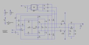
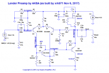
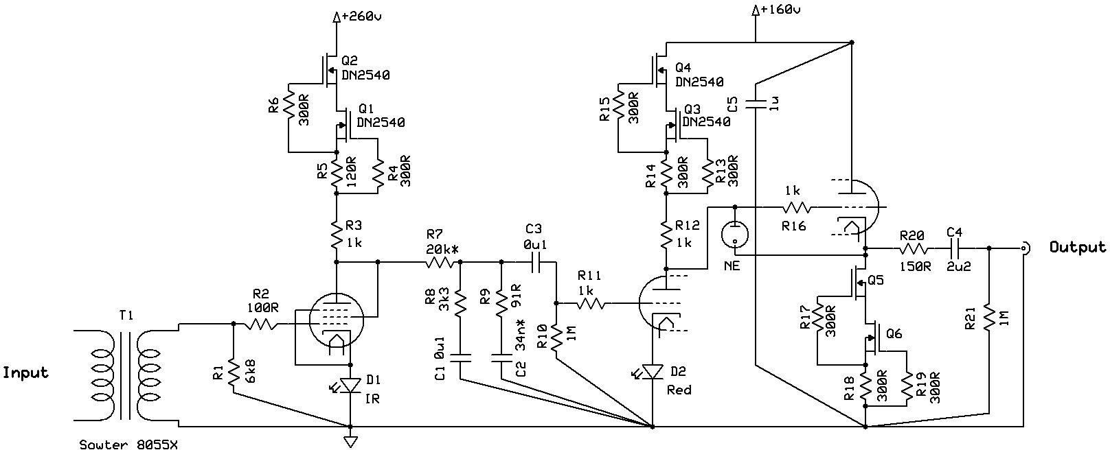
The schematic of the signal section is shown in Figure 5. The blocks will look completely familiar, but there's a few details that need explaining.
The implementation of the CCS loads is identical to that of the ImPasse preamp (I'm lazy and prefer to re-use good circuit blocks in all kinds of places). And like the ImPasse, each CCS is held at arms length from its tube by a resistor (R3 and R12). R5, R14, and R18 set the CCS currents, 20mA for the first stage, 10mA each for the next stage and the buffer. The values may have to be adjusted slightly, depending on the particulars of your batch of MOSFETs; this is most easily done by attaching the + end of the CCS to a power supply (24V or more) and the – end to a 100R dummy load resistor connected to ground. The 20mA CCS should be adjusted to get 2V across the dummy load, and (naturally) the 10mA CCS adjusted to get 1V. Exactitude isn't critical.
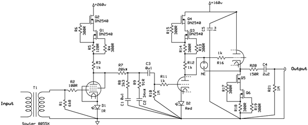
Figure 5: Signal Circuitry
Next question- what's R9 doing in there? This part is optional- some claim that there's a missing zero at 3.18us due to the rolloff of the Neumann cutter heads used to cut many records. Huge sonic advantages are claimed by adding this Missing Zero. Others disagree. Frankly, I can't hear a difference with the resistor in circuit or shorted out (though admittedly my old ears would be lucky to hit 15kHz on a good day), but am leaving it in the schematic as an option for those who believe that they CAN hear it.
The neon bulb between cathode and grid of the follower protects the tube at turn-on by limiting the voltage between grid and cathode to about 70-80V. This isn't quite as safe as the usual reverse-biased diode, but it's probably below the flashover point and doesn't have the nonlinear capacitance of a reverse-biased semiconductor diode. The neon will fire at turn-on, then go out as things start to warm up.
The output features a cathode stopper which helps ensure stability at the expense of slightly higher output impedance.
Q2 dissipates the most power of any of the devices so should get its own little heatsink. You can do the same for Q4 and Q5, but it's not quite as critical.
Pretty straightforward!
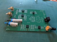
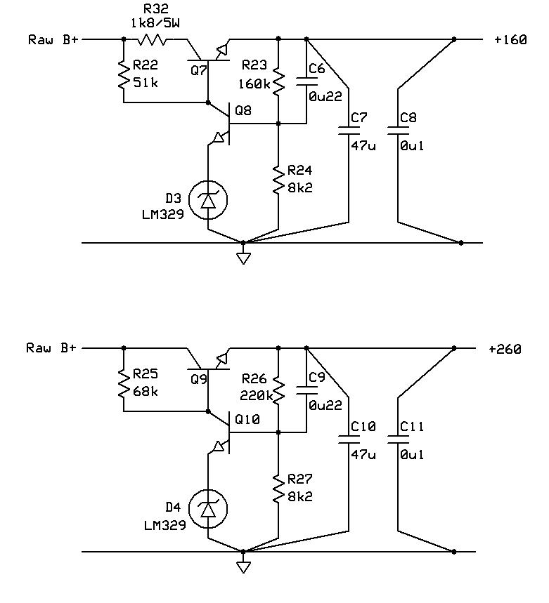
We move to the regulator circuits, shown in Figure 6. For the HV regulators, four are needed, two at 260V, two at 160V. This allows each channel to have separate regulation. Don't separate the feeds for the second gain stage and the cathode follower - things are most stable if they share a supply. These regulators are nothing fancy, but Good Enough considering the power supply rejection afforded by the extensive use of CCS loading. They're variations of the classic two transistor regulator I used for the Heretical and, in fact, I pressed some leftover Heretical circuit boards into service. Noise is low, stability is high, and the simplicity is appealing. One might substitute a MOSFET for the pass transistor, but the cheap plain-vanilla TIP50 works very well indeed.
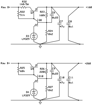
Figure 6: HV Regulators
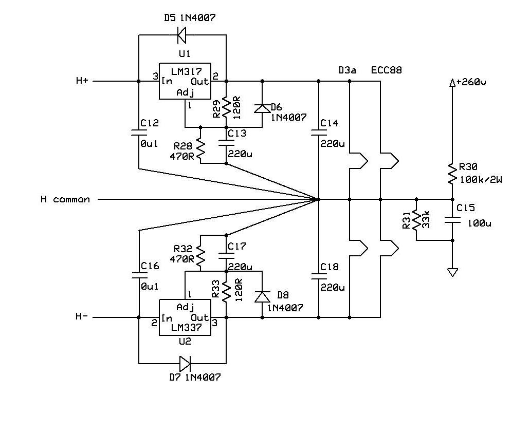
The regulator for the heaters is shown in Figure 7. As before, this is quite straightforward, an exercise in three pin regulation. But there are a few little twists. First among them is the seemingly odd choice of using two 6V regulators instead of one 12V regulator. This choice greatly increases common mode rejection, an Achilles' Heel of most heater power supplies; a common-mode choke will make things even better, but I just didn't have one. If you do, feel free to use it.
The more well-known twist is the use of R30 and R31 to elevate the heaters 65V above ground. This has two salutary effects - first, it reduces the heater-to-cathode strain of the cathode follower. For that tube, the cathode is roughly 95 volts above ground. Without this heater elevation, the heater-to-cathode voltage well exceeds the 50V limit for triode section one and strains the limits of triode section two. With 65 volts of elevation, the heater-cathode potential for the follower is a balmy 30V.
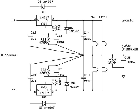
Figure 7: Heater supply regulators
The second salutary effect is that heater supply noise is less likely to be injected into the first or second stage cathodes. One thing that helps is that the cathodes are pretty well tied to AC ground (not degenerated). Nonetheless, noise can couple efficiently between heater and cathode via a diode-like interaction. Elevating the heaters seems to ameliorate that coupling. C15 ties the center of it all to AC ground. In the Raw Supply section, I'll mention one more trick to rid us of heater circuit noise.
In any event, the required heater current is about 600-700mA (depending on which ECC88 variant is used). With a raw H supply of about +/-10V, each regulator dissipates about 2.6W, so should be heatsinked.
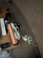
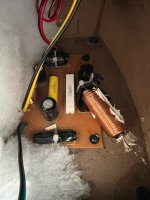
The External Power Supply
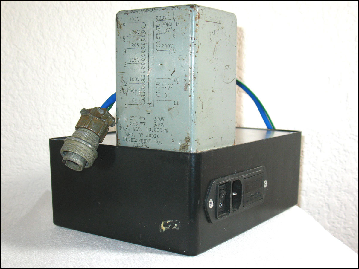
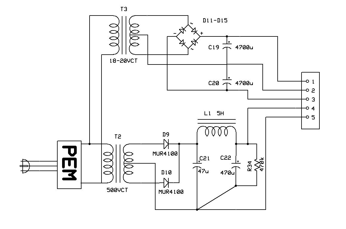
The raw supply is even more embarrassingly straightforward. It's built into a separate box using only the finest Radio Shack $10 cabinet (figure 8). I used mostly on-hand and surplus parts, but have given part numbers for some currently-available units. The HV power transformer was a lovely surplus item, potted and shielded. The one in the parts list is amazingly well-priced and should work fine. I'd avoid toroids since they are superbly efficient at coupling mains noise into the circuit.
A nice trick- use a separate transformer for the heater supply rather than the usual extra winding on the HV transformer. The reason for this is that, even using high speed soft recovery diodes, rectifier hash from the HV supply will be coupled to the heater winding, providing unwanted rattle. This is a minor effect, but we're handling microvolt signals…
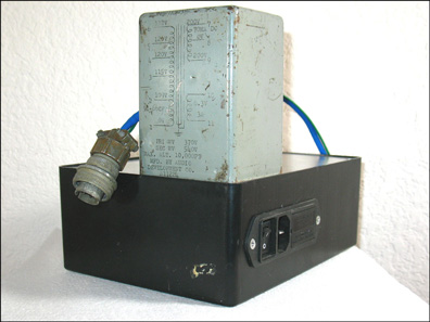
If you're extremely lazy (who, me?), there's a nice cheat that works great and saves money and effort- there are lots of wall-wart supplies available surplus. Find a couple of nice heavy ones (conventional supply rather than switching brick) rated at 9V/1A; I dug mine up for $2 each. They can be fit inside the power supply box in place of the discrete circuits. Nonetheless, I have indicated more generally available parts, but don't hesitate to visit a surplus shop and improvise. Again, laziness compelled me to use a power entry module (PEM), a chunk of plastic containing an IEC inlet, power switch, fuse, and RF line filter. I dug a pile of them out of a surplus bin for maybe $3 each- you should be able to do as well. The earth ground should be securely attached to any exposed metal parts (in my case, the top plate and HV transformer).
The sharp-eyed might have noticed that the transformer in the photo only has a 200V secondary. This was boosted to 230V by connecting the mains to the lowest primary tap. The raw B+ comes in at 285-300V, depending on the transformer, which allows a nice 25-40V cushion for the regulator (the higher the better).
The schematic for the raw supply is shown in Figure 9.
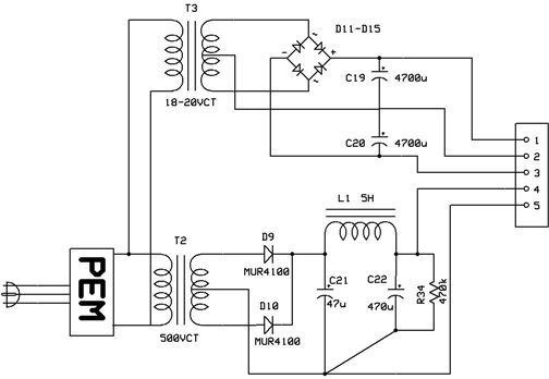
Figure 9: The raw supplies, high voltage and heater
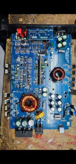
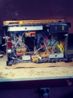
Building the Signal Circuit
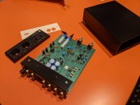
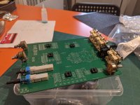
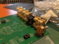
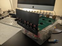
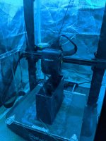
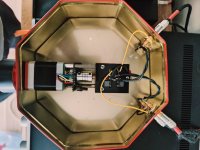
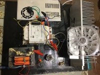
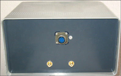
I freely admit that my first prototypes are usually a bit… rough. This one was no exception. The next build will be lovelier. But it does work. I found a Collins S-Line-style cabinet in the back of a surplus shop so grabbed it immediately. The front received a 5 pin DIN connector for the balanced phono, the rear took a surplus Amphenol connector for the power and RCA plugs for the single-ended output (Figure 10).
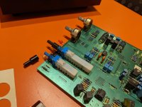
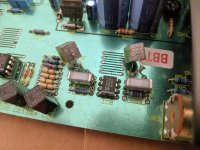
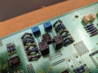
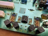
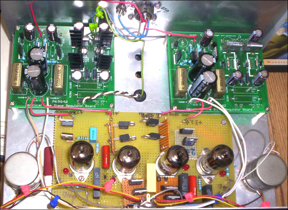
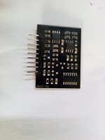
The internals are shown in Figure 11. Some digging around and filing got me a place to mount the perfboard. All signal and ground wiring was done with solid silver wire with Teflon sleeving. The schematics give a clue about the grounding- I used a combination of star and bus, with all grounds returning to a large solder tag right next to the input DIN jack.
Since the photos were taken, I've added heatsinks to the "upper" CCS transistors in the phono stage, twisted the gray and white transformer secondary leads on the lower right (I think forgetting that was one of my late-night moves), and added a 1k8/5W resistor in series with the collectors of the pass transistors for the 160V rail. I've also moved the earth ground lead from the raw supply from the chassis next to the power input plug (the blue wire) to the single point earth ground to the chassis next to the DIN input connector. This made a major difference in the noise floor, with a sharp reduction in odd harmonics of 60 Hz.
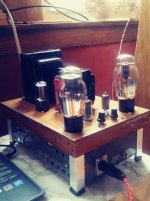
Tubes are, sadly, microphonic. This is one case where fanatic antiresonance measures and shock mounting really pay off. Me, I just put a piece of foam rubber on an old VPI turntable platform and stuck the preamp on there. No huge ringing problems, but a nice build will mechanically isolate the signal circuit so that I don't hear the constant whining about how trailer-trash the whole setup looks.
Designer components may be nice, but I just don't see the point. Use good-quality polypropylene coupling caps, carbon resistors for the gate and grid-stoppers, and 105°C-rated electrolytic caps in the power supply and regulators. As long as you don't look inside, the sound will be every bit as good as the fancy spread.
Trimming the RIAA network isn't too hard. Adjust the buildout resistor R7 to get the 1kHz response to be 20 dB below the 50Hz response. Then adjust C4 to give response at 20kHz at about -19dB with respect to 1kHz (if you're using the Missing Zero) or -19.6dB if you're not.

The cabling between power supply and signal circuit is likewise straightforward, but make sure you include a separate earth ground lead between the boxes so that all exposed metal parts are at safety (third pin) ground!
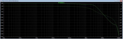
Proof of the Pudding
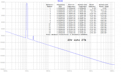
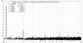
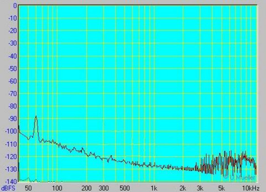
A noise spectrum of this box of gain, with the cartridge connected, is shown in Figure 12. It clearly follows the RIAA curve indicating that the primary noise source is indeed the cartridge and first stage. Total noise was measured over the range 20Hz to 20kHz with a 60Hz notch filter (the hum seems to be a function of how I run the cartridge-to-preamp interconnect) and found to be (unweighted) 0.16mV, which is very close to the noise prediction of -68dB with respect to 0.5V.
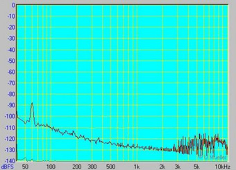
Figure 12: Noise spectrum with cartridge attached
The 60Hz spike was bothersome and, in fact, when I turned the volume to 11 and stood very near the speakers, I could barely hear it. But I could hear it… This was one of a continuing set of lessons in Small Things Count- I discovered that I had neglected to twist together the leads between the input transformer secondary and the D3a; once that was done, the tiny bit of residual hum disappeared.
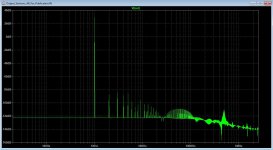
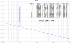
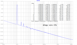
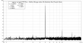
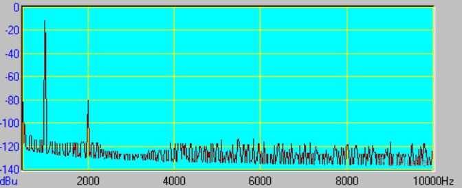
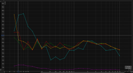
The spectrum of a 1kHz tone at 3VRMS output is shown in Figure 13; this was generated by feeding a signal through the attenuator in Figure 2, not from the actual cartridge. The second harmonic dominates at -70dB (0.03%). The THD is a strong function of the tube choice for the second voltage amplifier. For example, substitution of a 6KN8 raised the distortion to 0.06% (still predominantly second harmonic). An Amperex Bugle Boy clocked in at slightly under 0.05%, and the champion was the Siemens CCa at 0.03%. Swapping input tubes made almost no difference.
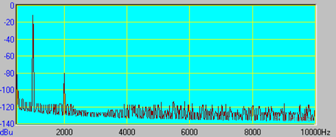
Figure 13. Spectrum of 1kHz tone at 3VRMS out
Speaking of input tubes, most D3a that I've checked needed some time to burn in before their grid current stabilized. One way to do this is to bake the tubes as suggested in "Valve Amplifiers," 3rd edition. I'm a bit leery of that method, worrying about compromising the glass-to-metal seal where the pins enter the envelope; my own choice is to burn in the tube
in situ, grinning and bearing the sound until all has reached equilibrium.
Enhancements
This preamplifier has several compromises for practicality. Chief among them is the coupling methods mentioned before- an all-out version would have a direct coupled output with a servo. I won't argue with anyone who'd go in that direction.
For more gain, the second stage tube could also be a D3a. Set its CCS load at 10mA and use a 1.7V red LED in the cathode. True studs will also use a D3a for the cathode follower- the transconductance and gain give it a theoretical advantage. In the Real World, the follower's performance is already quite impeccable, so this is really more for show than for go.
Sonics
I'm not one who is much for the purple prose of audio writers. Nor did I do a rigorous double-blind level matched test comparing this preamplifier to my old one. But, my uncontrolled subjective impressions were consistent with the measurements- quiet, clean, and unobtrusive. The shattering mistracking and noise on some of my older, lousier records seems to be much less noticeable. No oddball blats, buzzes, or shrieks. It's really pretty delightful.
Acknowledgments
So many discussions with so many people about phono stages! But I really should point to John Curl, Morgan Jones, and Allen Wright (
Vacuum State - High End Hifi Equipment) for many long and involved arguments that really shaped my thinking here. Many of the critical parts came out of Mr. Jones’s Locker. Tim de Paravicini declared this a "terrible" design, and I appreciate his input. Dave Dlugos (
planet_10 hifi) scrounged up the Technics MC, an amazing feat (can you find an EPC100C Mk4 that’s been in stasis?). Without Cynthia Wenslow, the mechanics of this article would have been impossible; all the good photos were hers (and her copyright, used with her kind permission), lousy ones were mine. Jan Didden (
Jan Didden audio diy and other human frailties place) was kind enough to run the SPICE simulation of the RIAA network and provide noise graphs, and suggested the name of this project. Following massive consumption of alcohol, I convinced Morgan Jones to read through the manuscript and make many helpful (and some downright insulting) suggestions, and for this I most sincerely thank him.
And as usual, great discussions amongst the denizens of diyAudio.com were a constant inspiration.
References and Further Reading:
Jim Hagerman, "On Reference RIAA Networks,," available at
www.hagtech.com/pdf/riaa.pdf
Morgan Jones, "Valve Amplifiers," 3rd edition, Newnes 2003.
Walt Jung, audioXpress 4/09 "High Performance Current Regulators Revised"
R. Landee, D. Davis, and A. Albrecht, "Electronic Designers' Handbook," McGraw-Hill 1957.
Stanley Lipshitz, "On RIAA Equalization networks," JAES 27:6, 458, 1979.
National Semiconductor, "Audio Radio Handbook," 1980.
Allen Wright, "The Tube Preamp Cookbook," 2nd Edition, Vacuum State Electronics, 1997.
Stuart Yaniger, audioXpress 2/09 "The ImPasse Preamplifier"
Stuart Yaniger, "The Heretical preamplifier," available at
SYclotron Audio The Heretical Preamp
PARTS LIST: SIGNAL CIRCUIT (one channel, two needed)
C1, C3 0u1 400V
C2 36n* 400V (33n plus trim for RIAA)
C4 2u2 250V
C5 1u 400V
D1 IR LED (1.25V)
D2 Red LED (1.7V)
D3-D4 LM329
NE Neon bulb (NE-2 or equivalent)
Q1-Q6 DN2540A
R1 6k8 0.5W
R2 100R 0.5W
R3, R11,
R12, R16 1k 0.5W
R4, R6, R13,
R14, R15, R 17,
R18, R19 300R 0.25W
R5 120R 0.25W
R7 20k* 0.5W (trim for RIAA)
R8 3k3 0.5W
R9 91R 0.5W
R10, R21 1M 0.5W
R20 150R 0.25W
T1 Sowter 8055X, 1:10 step-up transformer
V1 D3a pentode
V2 ECC88 or equivalent dual triode
PARTS LIST: HV REGULATORS (One channel, two needed)
C6, C9 0u22/400V
C7, C10 47u/400V
C8, C11 0u1/400V
Q7, Q9 TIP50A
Q8, Q10 MPSA42
R22 51k/2W
R23 160k/1W
R24, R27 8k2
R25 68k/2W
R26 220k/1W
PARTS LIST: HEATER REGULATOR (both channels, one needed)
C12, C16 0u1/100V
C13, C14,
C17, C18 220u, 25V
D5, D6
D7, D8 1N4007
R28, R32 470R
R29, R33 120R
R30 100k/2W
R31 33k/1W
U1 LM317
U2 LM337
PARTS LIST: RAW SUPPLIES (both channels, one needed)
C19, C20 4700uF/35V electrolytic capacitor
C21 47uF 450V electrolytic capacitor
C22 470uF 450V electrolytic capacitor
D9, D10 MUR4100EG fast recovery diodes (4A, 1000V)
D11-D15 5A, 100PIV (or more) rectifiers or bridge
L1 Choke, 5H/100mA or greater (Triode Electronics M100D)
R34 470k/2W
T2 Power Transformer, 250-0-250V, 100mA (Edcor XPWR001)
T3 Power transformer, 18-20VCT, 1A (Xicon 41FJ010 or Edcor PWRC20V1A-1)
PEM IEC Power entry module, 3A, with line filter, fuse, and switch
FIGURE CAPTIONS:
Figure 1. Passive EQ RIAA stage topology
Figure 2. Attenuator for measurements
Figure 3. First stage topology
Figure 4. Thermal noise from RIAA network
Figure 5. Signal circuitry
Figure 6. HV regulators
Figure 7. Heater supply regulators
Figure 8. The external raw supply
Figure 9. The raw supplies, high voltage and heater
Figure 10. Low-rent casework; a) DIN balanced in; b) RCA single-ended out
Figure 11: Low-rent innards. See text for changes since this photo.
Figure 12. Noise spectrum with cartridge attached.
Figure 13. Spectrum of 1kHz tone at 3VRMS out.