This Tuba PCB contains both an LC filter, to get rid of >50 kHz SMPS hash noise; AND also a of pair linear voltage regulators, to get rid of 100 Hz / 120 Hz hum. It's 2X filters. And just as 2X4 lumber is called two-by-four, this board is two-by-filters. Common mis-pronunciation is "two buh four" aka "tuba four". This board is thus "two buh filter" aka "tuba filter". Yes I know: too much information.
Each amplifier channel gets its own linear regulator, so Tuba provides an almost-dual-mono power supply arrangement. The left channel has no idea what the right channel is doing, or how loudly, so you get better stereo separation. Among other dual mono benefits.
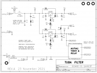
The key component which makes Tuba possible, is the LD1084 voltage regulator IC from ST Microelectronics. It's a 5 ampere, low dropout regulator, which gives excellent hum reduction (>60 dB @ 100 Hz) without dropping much supply voltage. That's the second, downstream filter.
The first, upstream, filter is a critically damped LC network, using an inductor whose DC resistance is only 0.067 ohms. Even at the SMPS max rated current (4.4 amps), it drops less than 0.3 volts. This is paired with a "DC Link" polypropylene film capacitor, for lowest possible ESR. I suggest you actively consider the Epcos B32653A4105 , or if that's not available, the Kemet R75GI41005 . Both have truly mind boggling specs for dV/dt. The LC resonant circuit is critically damped by C2 and R1, reducing its Q well below 0.5, thereby eliminating any possibility of ringing.
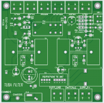
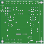
Gerbers are attached below; I very strongly recommend that you order PCBs with double thickness copper ("2 ounce copper"). There's nearly 5 amperes flowing in these traces! Make them thick and let the board run cool, run safe.
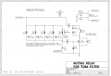
There is also a thump prevention relay circuit, on page 2 of the schematics. It is just a slightly fancier implementation of the thump preventer on the N-channel VFET supply filter board, designed by Nelson Pass. The same two-pole switch ("DPST") from the Nch VFET filter board is used. One pole turns power on and off, the other pole gives the thump preventer circuit a warning that the supply is about to collapse Right This Moment.
The speakers are muted "instantly" (with no delay) at power off. And the speakers are only un-muted after a long and leisurely delay from power on. PCB jumper options J9 thru J12 let you, the builder, choose the un-mute delay after power on: either 1, 5, 10, 15, or 20 seconds. Both of the beta testers set their PCBs for 10 seconds. And both were so happy with the results, they didn't bother to try the other delay options.
Tuba's choice of relay is mostly dictated by what parts are on the shelf today and not backordered for 24 months. That means: avoid the high demand relays (with 12 volt coils) and use the low demand relays (with 24 volt coils). Also avoid the small and cute, low profile relays; instead, use the big clunky ones that take up too much PCB realestate and are too tall. So I chose 653-G2R-24-DC24. Other relays that fit the board and work well are 655-RTE24024F and 651-2961192 .
The board fits inside the Modushop VFET chassis and its mounting holes align with the ventilation slots on the bottom cover, so you don't need to do any drilling. Its mounting holes are also aligned on the same 10 x 10 mm grid as the standard steel baseplate of the Modushop non-VFET chassis such as the Deluxe.
CAUTION
The Tuba filter is definitely NOT an appropriate project for a beginning or junior-intermediate builder. There's quite a few amperes of current flowing, and a very real possibility of destroying components by setting the board up incorrectly. It's also possible to ruin the board merely by adjusting it incorrectly (!) So unless you are a confident, experienced, knowledgeable builder -- don't mess with Tuba. Let someone else blow up their lab and their one of a kind VFET amp.
Because Tuba is a project for advanced hobbyists only, there isn't much more documentation than you see here; no "training wheels" build guides or Mouser shipping carts or troubleshooting tutorials. If you think you need those, maybe Tuba isn't the right project for you just yet.
ADJUSTING THE TRIMMERS: IT'S ALL ABOUT THE IN-TO-OUT VOLTAGE DROP
Find the three test points "TP1" , "TP2" , and "TP3" on both the schematic and the PCB. Adjusting the trimmers depends critically upon the voltages between these points. Solder a piece of 22AWG solid-core wire, sticking up about 1cm above the PCB, in each of those three places. Or use explicit "test pin" parts made by Keystone or Harwin. And get out your most accurate digital voltmeter.
Before you ever apply power to the Tuba board, turn both trimmer knobs ("VR1" and "VR2") all the way clockwise, to the right. This commands the LD1084 regulators to set their output voltage to the maximum possible value. Aha! Maximum Vout gives minimum (in-to-out) voltage drop.
With no load attached, and certainly with no front end boards or amp channel boards attached, connect Tuba to the on-off switch and to the Mean Well SMPS. Turn it on and wait 60 seconds. While you're waiting you'll hear the muting relay click; that's the un-mute delay. If you don't see any flames or smell any smoking parts, proceed.
Connect your DVM positive lead to TP1 using crocodile clips. Connect DVM negative lead to TP2 using crocodile clips. Now slowly turn trimmer VR1 counterclockwise while watching the voltmeter. Keep turning until the meter reads 2.0 volts from TP1 to TP2. That's the in-to-out voltage drop of the CH1 regulator. Congratulations.
Now move the DVM negative lead to TP3 instead of TP2. Slowly turn trimmer VR2 counterclockwise while watching the voltmeter. Keep turning until the meter reads 2.0 volts from TP1 to TP3. That's the in-to-out voltage drop of the CH2 regulator. Congratulations. You've completed phase 1 of the adjustment. Now you can finish wiring up Tuba's DC outputs
PHASE 2 OF ADJUSTING THE TRIMMERS: WITH ALL BOARDS POWERED
After you've connected all of the wiring among all of the PCBs, it's time to perform the final adjustments on VR1 and VR2. Start by attaching your DVM to TP1 and TP2, and turning the amplifier on. Wait 60 seconds. If you don't see any flames or smell any smoking parts, proceed.
Check the in-to-out voltage drop from TP1 to TP2. Connecting the high power, class-A amplifier boards to the SMPS, has probably caused a change in this voltage. It's probably not 2.0 volts now, and that's normal. Slooooowly turn VR1's knob to return the in-to-out voltage back to 2.0 volts.
If turning the knob a little bit (1/4 turn) has no effect: STOP!! Your setup is somehow wrong. Your meter is connected to the wrong test points, or you are dialling the wrong trimmer, (VR2 instead of VR1), or you've made some other mistake. Don't keep turning the knob, you'll probably destroy the Tuba board. Turn power off, unplug the power cord, and take a 15 minute break. Then double and triple check your setup.
Once CH1 has got 2.0 volts from in-to-out (i.e. from TP1 to TP2), move the meter lead from TP2 to TP3 and work on CH2. Slooooowly turn VR2's knob to return the in-to-out voltage back to 2.0 volts. Done! Victory!
TUBA CONTAINS TWO FILTERS . . . BUT NOTICE WHAT IT DOESN'T CONTAIN
Tuba doesn't include great big electrolytic capacitors. All it's got is 33 microfarads on the input and 33 microfarads on the output, of each regulator IC.
There simply isn't room.
In my opinion, thanks to the Class-A load current, Tuba doesn't actually _need_ great big electrolytic capacitors on either input or output. In my opinion, Tuba will work quite well with the Class-A VFET amps and deliver great sound. And Tuba will also annihilate that 100 Hz peak on your FFT plots, whether it was audible or not.
There are probably diyA members who don't agree; folks who firmly believe that Tuba's lack of 33,000 microfarad capacitors is a fatal flaw. Which is fine; simply accept that Tuba is definitely not what you want, and move on. Or maybe perform some experiments which attach additional supply capacitance somewhere else inside the chassis, but not on the Tuba filter PCB.
Or maybe, create a new and bigger filter PCB of your own, which does contain all of the electrolytic capacitors that you believe are necessary. Perhaps including some of the elements on Tuba (damped LC filter for >50 kHz noise // LD1084 voltage regulator for 100 Hz noise // thump prevention relay) or none of the elements on Tuba. It's your drafting table, draw up whatever appeals to you.
_
Each amplifier channel gets its own linear regulator, so Tuba provides an almost-dual-mono power supply arrangement. The left channel has no idea what the right channel is doing, or how loudly, so you get better stereo separation. Among other dual mono benefits.
The key component which makes Tuba possible, is the LD1084 voltage regulator IC from ST Microelectronics. It's a 5 ampere, low dropout regulator, which gives excellent hum reduction (>60 dB @ 100 Hz) without dropping much supply voltage. That's the second, downstream filter.
The first, upstream, filter is a critically damped LC network, using an inductor whose DC resistance is only 0.067 ohms. Even at the SMPS max rated current (4.4 amps), it drops less than 0.3 volts. This is paired with a "DC Link" polypropylene film capacitor, for lowest possible ESR. I suggest you actively consider the Epcos B32653A4105 , or if that's not available, the Kemet R75GI41005 . Both have truly mind boggling specs for dV/dt. The LC resonant circuit is critically damped by C2 and R1, reducing its Q well below 0.5, thereby eliminating any possibility of ringing.
Gerbers are attached below; I very strongly recommend that you order PCBs with double thickness copper ("2 ounce copper"). There's nearly 5 amperes flowing in these traces! Make them thick and let the board run cool, run safe.
There is also a thump prevention relay circuit, on page 2 of the schematics. It is just a slightly fancier implementation of the thump preventer on the N-channel VFET supply filter board, designed by Nelson Pass. The same two-pole switch ("DPST") from the Nch VFET filter board is used. One pole turns power on and off, the other pole gives the thump preventer circuit a warning that the supply is about to collapse Right This Moment.
The speakers are muted "instantly" (with no delay) at power off. And the speakers are only un-muted after a long and leisurely delay from power on. PCB jumper options J9 thru J12 let you, the builder, choose the un-mute delay after power on: either 1, 5, 10, 15, or 20 seconds. Both of the beta testers set their PCBs for 10 seconds. And both were so happy with the results, they didn't bother to try the other delay options.
Tuba's choice of relay is mostly dictated by what parts are on the shelf today and not backordered for 24 months. That means: avoid the high demand relays (with 12 volt coils) and use the low demand relays (with 24 volt coils). Also avoid the small and cute, low profile relays; instead, use the big clunky ones that take up too much PCB realestate and are too tall. So I chose 653-G2R-24-DC24. Other relays that fit the board and work well are 655-RTE24024F and 651-2961192 .
The board fits inside the Modushop VFET chassis and its mounting holes align with the ventilation slots on the bottom cover, so you don't need to do any drilling. Its mounting holes are also aligned on the same 10 x 10 mm grid as the standard steel baseplate of the Modushop non-VFET chassis such as the Deluxe.
CAUTION
The Tuba filter is definitely NOT an appropriate project for a beginning or junior-intermediate builder. There's quite a few amperes of current flowing, and a very real possibility of destroying components by setting the board up incorrectly. It's also possible to ruin the board merely by adjusting it incorrectly (!) So unless you are a confident, experienced, knowledgeable builder -- don't mess with Tuba. Let someone else blow up their lab and their one of a kind VFET amp.
Because Tuba is a project for advanced hobbyists only, there isn't much more documentation than you see here; no "training wheels" build guides or Mouser shipping carts or troubleshooting tutorials. If you think you need those, maybe Tuba isn't the right project for you just yet.
ADJUSTING THE TRIMMERS: IT'S ALL ABOUT THE IN-TO-OUT VOLTAGE DROP
Find the three test points "TP1" , "TP2" , and "TP3" on both the schematic and the PCB. Adjusting the trimmers depends critically upon the voltages between these points. Solder a piece of 22AWG solid-core wire, sticking up about 1cm above the PCB, in each of those three places. Or use explicit "test pin" parts made by Keystone or Harwin. And get out your most accurate digital voltmeter.
Before you ever apply power to the Tuba board, turn both trimmer knobs ("VR1" and "VR2") all the way clockwise, to the right. This commands the LD1084 regulators to set their output voltage to the maximum possible value. Aha! Maximum Vout gives minimum (in-to-out) voltage drop.
With no load attached, and certainly with no front end boards or amp channel boards attached, connect Tuba to the on-off switch and to the Mean Well SMPS. Turn it on and wait 60 seconds. While you're waiting you'll hear the muting relay click; that's the un-mute delay. If you don't see any flames or smell any smoking parts, proceed.
Connect your DVM positive lead to TP1 using crocodile clips. Connect DVM negative lead to TP2 using crocodile clips. Now slowly turn trimmer VR1 counterclockwise while watching the voltmeter. Keep turning until the meter reads 2.0 volts from TP1 to TP2. That's the in-to-out voltage drop of the CH1 regulator. Congratulations.
Now move the DVM negative lead to TP3 instead of TP2. Slowly turn trimmer VR2 counterclockwise while watching the voltmeter. Keep turning until the meter reads 2.0 volts from TP1 to TP3. That's the in-to-out voltage drop of the CH2 regulator. Congratulations. You've completed phase 1 of the adjustment. Now you can finish wiring up Tuba's DC outputs
PHASE 2 OF ADJUSTING THE TRIMMERS: WITH ALL BOARDS POWERED
After you've connected all of the wiring among all of the PCBs, it's time to perform the final adjustments on VR1 and VR2. Start by attaching your DVM to TP1 and TP2, and turning the amplifier on. Wait 60 seconds. If you don't see any flames or smell any smoking parts, proceed.
Check the in-to-out voltage drop from TP1 to TP2. Connecting the high power, class-A amplifier boards to the SMPS, has probably caused a change in this voltage. It's probably not 2.0 volts now, and that's normal. Slooooowly turn VR1's knob to return the in-to-out voltage back to 2.0 volts.
If turning the knob a little bit (1/4 turn) has no effect: STOP!! Your setup is somehow wrong. Your meter is connected to the wrong test points, or you are dialling the wrong trimmer, (VR2 instead of VR1), or you've made some other mistake. Don't keep turning the knob, you'll probably destroy the Tuba board. Turn power off, unplug the power cord, and take a 15 minute break. Then double and triple check your setup.
Once CH1 has got 2.0 volts from in-to-out (i.e. from TP1 to TP2), move the meter lead from TP2 to TP3 and work on CH2. Slooooowly turn VR2's knob to return the in-to-out voltage back to 2.0 volts. Done! Victory!
TUBA CONTAINS TWO FILTERS . . . BUT NOTICE WHAT IT DOESN'T CONTAIN
Tuba doesn't include great big electrolytic capacitors. All it's got is 33 microfarads on the input and 33 microfarads on the output, of each regulator IC.
There simply isn't room.
In my opinion, thanks to the Class-A load current, Tuba doesn't actually _need_ great big electrolytic capacitors on either input or output. In my opinion, Tuba will work quite well with the Class-A VFET amps and deliver great sound. And Tuba will also annihilate that 100 Hz peak on your FFT plots, whether it was audible or not.
There are probably diyA members who don't agree; folks who firmly believe that Tuba's lack of 33,000 microfarad capacitors is a fatal flaw. Which is fine; simply accept that Tuba is definitely not what you want, and move on. Or maybe perform some experiments which attach additional supply capacitance somewhere else inside the chassis, but not on the Tuba filter PCB.
Or maybe, create a new and bigger filter PCB of your own, which does contain all of the electrolytic capacitors that you believe are necessary. Perhaps including some of the elements on Tuba (damped LC filter for >50 kHz noise // LD1084 voltage regulator for 100 Hz noise // thump prevention relay) or none of the elements on Tuba. It's your drafting table, draw up whatever appeals to you.
_
Attachments
Last edited:


Thanks, Mark - that looks very interesting !
I've long been a fan of the similar LT1084 regulator - have used that and the sadly discontinued LT1083 for more than 10 years, from tube filament regulators through bias supplies, preamp PSUs to Raspberry Pi DAC regulators ... 🙂
Regards, Claas
I've long been a fan of the similar LT1084 regulator - have used that and the sadly discontinued LT1083 for more than 10 years, from tube filament regulators through bias supplies, preamp PSUs to Raspberry Pi DAC regulators ... 🙂
Regards, Claas
Many thanks for designing and sharing this, Mark! Very generous.
Hash filter and ripple-filter/reg all on one board - what's not to like? Should work great with my MoFo build.
cheers, Derek
Hash filter and ripple-filter/reg all on one board - what's not to like? Should work great with my MoFo build.
cheers, Derek
This is great! Thanks Mark!! I especially like the ‘variable’ thru holes for the smaller electrolytics. Smart.
Thanks Mark!
this is designed for the first VFET p-chn amp?
Does it eliminate the both the on and off thumps (the latter being the more annoying one)?
Does this substitute the original SMPS filter or is in addition to that?
this is designed for the first VFET p-chn amp?
Does it eliminate the both the on and off thumps (the latter being the more annoying one)?
Does this substitute the original SMPS filter or is in addition to that?
I have 10 boards due to arrive around 12-8....there will be 8 to sell at cost if interested.
Thanks for making a run of these!! I'll take 1!
I have 10 boards due to arrive around 12-8....there will be 8 to sell at cost if interested.
If you can send these to the UK, could I have two boards please?
Best wishes.
Thanks for making a run of these!! I'll take 1!
Yup….as soon as they arrive I’ll get the details. I’ll let ya know.
If you can send these to the UK, could I have two boards please?
Best wishes.
Yup….as soon as they arrive I’ll get the details. I’ll let ya know.
Looking forward to the PCB Monk55! Thank you again for facilitating the PCB run!
My mouser parts are ordered. Some parts are running at low quantity. I'm usually a Digikey guy, but they were sold out of some the parts. Mouser had all of the parts I need for this that weren't already on my shelf, plus what I needed on 2 other little projects.
My mouser parts are ordered. Some parts are running at low quantity. I'm usually a Digikey guy, but they were sold out of some the parts. Mouser had all of the parts I need for this that weren't already on my shelf, plus what I needed on 2 other little projects.
Seems like the relay options were all significantly less expensive at Mouser, last time I looked. Biggest single line item cost is for the AWG-10 capable terminal blocks, oof.
- Home
- Amplifiers
- Pass Labs
- Tuba SMPS filter: two linear regulators inside VFET/Theseus chassis; incl thump kill