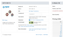
If you're going to pull (2 x 2.5 amps) through one inductor, I recommend you choose a part whose max rated current is at least 20% higher, namely 6A or more. Such as the 7A inductor shown below. Changing to two inductors (one L+C+DampingSnubber filter per regulator) would provide an even greater margin of safety.
I recommend 2V for the in-to-out voltage drop, because it gives a safety margin in both directions. If your voltmeter is wrong by -10%, or wrong by +10%, in either case the regulator will still remain not-dropped-out and the power dissipated into the heatsink {at 2.2 amps per channel -- the maximum possible output current of the VFET amp's Mean Well GST160A36 SMPS} will still keep the regulator IC's junction temperature in spec. 2V also gives some safety margin if you set the trimmers at one air temperature, but run the amp at a different air temperature.
If a builder wishes to reduce the in-to-out voltage drop below 2V, that's not what I recommend. It might work; it might work GREAT; I simply don't know. The Tuba Filter's design is aimed at the VFET amp with a 160 Watt, 36 volt switcher -- and nothing else. The circuit tradeoffs and optimizations assume that specific SMPS and operating condition. If somebody wants to try it in a different environment, they are welcome to go right ahead; just don't pretend there's any guarantee or expectation of success. It might work; it might work GREAT. I simply don't know.
I do suggest that anyone planning to dissipate more than (2.2 amps X 2.0 volts = 4.4 watts) per regulator, really ought to invest in some Keratherm Red thermal pads from the diyAudio Store. You're going to need to all the (thermal) help you can get.
_
Attachments
Many, many thanks Mark. Much appreciated.
I acknowledge and accept that off-label use of your TUBA filter and reg comes with some risks/unknowns. But it's just such a nice, compact board that it cries out to be used in other setups. I will experiment and see. I am using Keratherm Red pads. And I'll test the voltage drop with a freshly calibrated diy millivolt meter. I'll go with 1.8V to be on the safer side.
cheers, Derek
Hi Mark,If you're going to pull (2 x 2.5 amps) through one inductor, I recommend you choose a part whose max rated current is at least 20% higher, namely 6A or more. Such as the 7A inductor shown below. Changing to two inductors (one L+C+DampingSnubber filter per regulator) would provide an even greater margin of safety.
I recommend 2V for the in-to-out voltage drop, because it gives a safety margin in both directions. If your voltmeter is wrong by -10%, or wrong by +10%, in either case the regulator will still remain not-dropped-out and the power dissipated into the heatsink {at 2.2 amps per channel -- the maximum possible output current of the VFET amp's Mean Well GST160A36 SMPS} will still keep the regulator IC's junction temperature in spec. 2V also gives some safety margin if you set the trimmers at one air temperature, but run the amp at a different air temperature.
If a builder wishes to reduce the in-to-out voltage drop below 2V, that's not what I recommend. It might work; it might work GREAT; I simply don't know. The Tuba Filter's design is aimed at the VFET amp with a 160 Watt, 36 volt switcher -- and nothing else. The circuit tradeoffs and optimizations assume that specific SMPS and operating condition. If somebody wants to try it in a different environment, they are welcome to go right ahead; just don't pretend there's any guarantee or expectation of success. It might work; it might work GREAT. I simply don't know.
I do suggest that anyone planning to dissipate more than (2.2 amps X 2.0 volts = 4.4 watts) per regulator, really ought to invest in some Keratherm Red thermal pads from the diyAudio Store. You're going to need to all the (thermal) help you can get.
_
How about going lower voltage? Something for the ACA mini and the 24V SMPS? Could at least the LC+RC filter portion be adapted to that?
thanks
Mark,
after looking at your schematic, the datasheets and the application note for HV use of the LM317 and derivatives I would like to ask 2 questions:
1. What is the reason you settled on 12.75V (ish) for the delta on Vin - Vout for the regulator (that's the way I understood it at least)? Halfway between Min and Max as per Datasheet ?
The only other correlation I could find was the current on the Adj pin getting somewhat higher at voltages above say 12V, but I don't see how that would be critical.
2. Why did you choose not to bypass the Adj resistors by a cap as suggested by Datasheet for higher ripple rejection ?
I understand you stated trade-offs etc. in the very first post of your thread etc. but would be curious to understand your reasoning.
I am absolutely not proficient in EE stuff, rather the classic painting by numbers guy and will totally accept a "simulate and/or measure it yourself" type response.
Thanks,
Max
Here's a pic of my "Franken-Tuba", built for 24V @ 2.5A per channel with a separate hash filter for each channel. To get 24V output, I used 1K5 ohms resistors for R2 and R3. The filter and reg is paired with two Mean Well RS-150-24 smps each rated for 6.5A with adjustable output voltage of up to 26.4V.
If I can get cleaner scope traces, I will post some scope shots this wknd. I don't have fancy differential probes, so my first attempts at measuring ripple and hash noise were plagued by coupled interference. But I was able see a sawtooth ripple pattern out of the smps and after the hash filter (which wouldn't be expected to smooth the ripple, just eliminate HF hash noise), and then, most importantly, a somewhat fuzzy but flat trace for the dc output after the reg. Much if not all of the fuzz is likely coupled noise from the environment. This wknd, I will try to gerry-rig a poor man's version of differential probes using the "subtract" function on the scope - something I saw on EEVblog.
But long story short: it works! Very pleased. Many thanks again to Mark for sharing his design.
Edit: I now need to figure out how to modify the Thump killer circuit for 24V. I'll work on that next week.
@grataku: the 1084 datasheet provides the formula and method for changing the output voltage: Vout = 1.25*(1+R2/R1). In the Tuba filter, R2 is comprised of the series combination of R2 (or R3 in the case of the other channel) and the 1K trimmer pot; and R1 is 120 ohms. Since I wanted a regulated output of 24V, I solved for R2 and got approx. 2K2 ohms. Since the 1K trimmer can be adjusted from 0 to 1K ohms, I arbitrarily picked it's midpoint of 500 ohms, which meant I needed R2 and R3 values of about 1K7 ohms. I didn't have any resistors in that value on hand, but had a bunch of 1/2W 1K5 resistors, and so I used them. But to deal with the voltage drop across the 1084 reg, you'll need a supply of approx. 26V to get regulated 24V out. I'm not sure if the 24V Mean Well wall warts permit adjustment. As per above, my smps allows for up to 26.4V output.
cheers, Derek
I should add that for the purpose of the Vout formula above, R1 of the formula is R4 (or R5) on the Tuba board: 120 ohms.
Looks good!I should add that for the purpose of the Vout formula above, R1 of the formula is R4 (or R5) on the Tuba board: 120 ohms.
Thanks! I would be happy with just having the filter adapted with no regulator.
If you just want the hash filter, why not try Mark's "PO89ZB": po89zb-an-inline-dc-filter
It's currently sold out at the diyAudio Store, but Mark has posted the gerber files in Post #1.
cheers, Derek
It's currently sold out at the diyAudio Store, but Mark has posted the gerber files in Post #1.
cheers, Derek
What is the reason you settled on 12.75V (ish) for the delta on Vin - Vout for the regulator (that's the way I understood it at least)? Halfway between Min and Max as per Datasheet ?
The IC regulator's (Vin - Vout) is 2.0 volts after adjusting the trimmer potentiometers. See the section of post #1 in this thread, headed "It's all about the in-to-out voltage drop".
The trimmers (appear to) have a needlessly large adjustment range. On the other hand, they also have a needlessly fine grained tune-ability thanks to being 25-turn pots. The latter cancels the former and the result is good flexibility without fiddly (1/16th turn) micro-adjustments.
I have two extra boards that I will send for free to anyone in Canada or the US. They are 2 oz boards. Although I don't want payment, please consider a making a small donation to diyAudio (for example, $5).
PM me with your address if interested.
cheers, Derek
PM me with your address if interested.
cheers, Derek
Mark,The IC regulator's (Vin - Vout) is 2.0 volts after adjusting the trimmer potentiometers. See the section of post #1 in this thread, headed "It's all about the in-to-out voltage drop".
The trimmers (appear to) have a needlessly large adjustment range. On the other hand, they also have a needlessly fine grained tune-ability thanks to being 25-turn pots. The latter cancels the former and the result is good flexibility without fiddly (1/16th turn) micro-adjustments.
Thanks for that reply, I was mistaken about the Vin -Vout delta, the question I wanted to ask actually is why a 14V Zener, I understand it's to extend the voltage range... but I'll read up further on the topic and should find answers!
1 board left - although the future recipient of the first board has indicated that he will take both boards if no one else expresses interest. So if you want the last board, please left me know by tomorrow (Thursday) before 1 pm EST (NYC/Toronto time).
cheers, Derek
cheers, Derek
I had a fun and educational afternoon studying and breadboarding Mark's thump kill circuit and then modifying it to work with 24V V+. I think I managed to figure out its basic workings -- the only thing that confuses me is the purpose of the reverse diode across the 470K resistor that forms part of the first leg of the timer section of the circuit. My guess is that it allows the 33uF cap to quickly discharge (thus turning off the mosfet) on power down/interruption. If that's the case, am I correct in thinking that the cap drains through the grounded resistive divider that sets Vout on the 1084 reg???
I used an LED to indicate when the relay switched "on" (you can also just listen for the click sound, but that's difficult to capture in a photo ... 😗). After testing the circuit with stock values @ 36V to make sure I breadboarded it correctly, I modified and tested the circuit at 24V by replacing the stock 12V zener in front of the relay coil with a piece of wire, and replaced the stock 24V zener that feeds the gate of the mosfet with a 12V zener. With the 470K forming the first leg of the timer circuit, I get a turn on delay of about 13 seconds or so - which is fine by me.
Here are a couple of pics. The meter shows the voltage across the 33uF cap. It was interesting to watch the cap charge -- quickly at first and then slowing, as one would expect.
Am I missing any other needed changes?
cheers and thanks, Derek
D1 discharges C7 if some dunderhead decides to turn the amp off by cutting the AC mains, instead of flipping the power switch to its OFF position. They beg Nelson for a thump killer, he designs one, they build his thump killer PCB, they upgrade to the not-inexpensive Tuba board with its extra fancy thump killer, and then they completely circumvent its functionality. Ugh.
When the mains is cut, both amplifier channels continue to draw 1.6 amperes of class-A bias current, for as long as they can. This discharges the supply rails right quick like.
When the mains is cut, both amplifier channels continue to draw 1.6 amperes of class-A bias current, for as long as they can. This discharges the supply rails right quick like.
Many thanks Mark for the explanation. Not sure if the "circumventing its functionality" concern was directed at me. Have I done that? I was aiming for the opposite: to preserve all functionality, but at 24V supply. Although I did wonder whether I should reduce the 43V zener protecting the mosfet to a lower value (e.g, 30 to 32V) in light of the lowered V+....they upgrade to the not-inexpensive Tuba board with its extra fancy thump killer, and then they completely circumvent its functionality. Ugh.
No, the member who uses his "Home Automation" system to cut the juice to his audio rack. D1 is a last ditch attempt to make THAT thump smaller.
@Monk55
I just noticed the board came with oversized holes for many components. I can't tell if it was designed like that or was a production issue.
There maybe others but I am one one of those that abandoned switches a while ago.
I just noticed the board came with oversized holes for many components. I can't tell if it was designed like that or was a production issue.
I think It's directed at me. I turn off the stereo with a wifi power plug from the phone. 😉Many thanks Mark for the explanation. Not sure if the "circumventing its functionality" concern was directed at me. Have I done that? I was aiming for the opposite: to preserve all functionality, but at 24V supply. Although I did wonder whether I should reduce the 43V zener protecting the mosfet to a lower value (e.g, 30 to 32V) in light of the lowered V+.
There maybe others but I am one one of those that abandoned switches a while ago.
Last edited:
The Tuba PCB does have big holes, to facilitate repairs. Un-soldering and removing components is a lot easier with big holes, especially when using vacuum tools like the Edsyn Soldapullt or the Hakko FR-301.
Understood.The Tuba PCB does have big holes, to facilitate repairs. Un-soldering and removing components is a lot easier with big holes, especially when using vacuum tools like the Edsyn Soldapullt or the Hakko FR-301.
- Home
- Amplifiers
- Pass Labs
- Tuba SMPS filter: two linear regulators inside VFET/Theseus chassis; incl thump kill