Black TUBA boards, with lovely 2oz traces, arrived from China this afternoon. As did the Mouser order.
Finishing up SissySIT R3 this week. Hope to listen to it while assembling TUBA, and perhaps other boards for VFET (OS, Bulwark, Dreadnought) this weekend
VFET pre-orders over now, I think. 2-3 months for the chassis? Might as well take my time on board building.
Finishing up SissySIT R3 this week. Hope to listen to it while assembling TUBA, and perhaps other boards for VFET (OS, Bulwark, Dreadnought) this weekend
VFET pre-orders over now, I think. 2-3 months for the chassis? Might as well take my time on board building.

My room is too full of stuff right now To be ordering more stuff. Once I finish the boards I have, I’ll consider others waiting for the chassis.
I had this same thought. I assume this is only for VFet amps and not for others like F-5My apologies up front - this is probably an extremely dumb question...
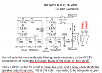
I think I understand how this circuit works and it's very cool. I've ordered one for my VFET OS2 kit. But my question is: Why doesn't shorting the output to ground damage the output section? Other amps I've worked on are easily damaged if the speaker outputs are shorted together.
The output is coupled through a 10000 uF cap. At turn on, it is a dead short and so the speaker will see 18V. That’s when you want to short the output to ground. After the cap charges up, it is like an open circuit for DC.
I got the boards, thanks.Sure, PM me your info and I’ll get a pair out to you.
Just send me a private mail and i shall send you oneInterested in a Tuba PCB. If you have one you can spare, let me know. Located in US.
Thx
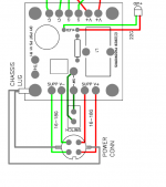
"SUPP_V+" and "SUPP_GND" each have a 2-hole wire-to-board Euroblox connector, because Nelson Pass's original VFET power supply filter board also had 2 holes for V+ (red in picture below) and 2 holes for GND/V- (green in picture 1 below). If you decide to solder all four of these wires to the panel mounted DIN connector that brings in DC from the Mean Well brick (as Nelson's picture shows), the Tuba board provides Euroblox connector holes for all four of them. Tuba is backward compatible with original VFET lottery amps.
However, if you decide to only solder two wires to the DIN connector (as suggested in the diagram of post #97 above) then you only use two of the four Euroblox connector holes and leave the other two empty.
The connection from V+ to switch pole 1 is already provided on the PCB; you don't need the external wire shown in picture 2 below, and installing it is an unnecessary risk. Especially since you may forget the contents of this message between today and when you service the amplifier.
Tuba is designed to work with either a DPST switch or a DPDT switch. For the latter, the connections shown in post #97 are correct. Use your connectivity tester / DVM to discover the proper pin connections, so the OFF and ON markings on the switch are right side up.
_
Attachments
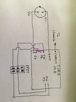
Thanks Mark! And thanks for crossing out the line on my diagram. I drew it to represent the connection on the PCB, not an external wireand so, yes, it need not be shown.
But I am glad I got the rest of it right. It is a little odd when the switch connections go to the PCB and it took me quite a while to figure it out.
I plan to use just one set of wires from the power connector to the PCB.
But I am glad I got the rest of it right. It is a little odd when the switch connections go to the PCB and it took me quite a while to figure it out.
I plan to use just one set of wires from the power connector to the PCB.
My Tuba board works fine for making V+, both channels function great for that. The muting circuit is not working though. When I first fired up my VFET amp, I got no sound. Appropriate voltage at OS boards. I detached the connections from the speaker connections on the Tuba board, and without being muted, the amp makes music.
I’m assuming that I put something in backwards, causing the mute to be permanent. I plan to disassemble the amp over the 4th of July weekend, to check over the parts. That chassis is too small to see anything.
Any ideas on the prime suspects? Some situation that keeps the mute circuit activated.
I’m assuming that I put something in backwards, causing the mute to be permanent. I plan to disassemble the amp over the 4th of July weekend, to check over the parts. That chassis is too small to see anything.
Any ideas on the prime suspects? Some situation that keeps the mute circuit activated.
- Home
- Amplifiers
- Pass Labs
- Tuba SMPS filter: two linear regulators inside VFET/Theseus chassis; incl thump kill