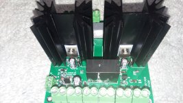


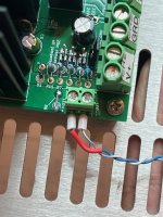
A couple thoughts; the pads for the variable could be larger as could the ones for the stakes on the heat-sink. You can see I just made a nasty big solder ball on the stake for stability. Also, you can see where it's not a good idea to bend the 5W diode when mounted flush. A slightly larger hole for the stake hole too. It's just able to fit the diode, and makes removal precarious with regards to pads. This is an older design from Mark, but if you are planing on having a board made, you might consider these few changes.
I got around to testing the Tuba today, something isn't right, I have 35V on the outputs and a drop of 1v across the test points, and VR does nothing. I checked all the diodes and resistors, all appears to be right there. All the caps are correct. The relay works as it should. I have LM1084 in place of the LD1084, as far as I can tell that should be okay?
It's a pretty simple circuit, but I'm missing something.
I followed Marks power up and test procedure too.
It's a pretty simple circuit, but I'm missing something.
I followed Marks power up and test procedure too.
Last edited:
Update & Warning!: The LM1084 is not a direct swap, for those that can't find the LD1084. I'm sure it would work with some tweaks, but not as designed. I found some LD1084s I didn't know I had and swapped them in... adjustment perfect, no issues at all.
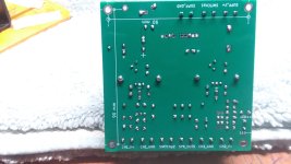
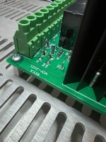
The holes are pretty close to the component size on these and I pulled a trace and had to pull a cap and solder that pin from the top. Hint: if you have very close ID/OD I found it best to heat, or even add solder then heat all and pull the part. After the part is removed, you can go back and clear the holes. 😉
The holes are pretty close to the component size on these and I pulled a trace and had to pull a cap and solder that pin from the top. Hint: if you have very close ID/OD I found it best to heat, or even add solder then heat all and pull the part. After the part is removed, you can go back and clear the holes. 😉
Last edited:
I would like to use this tuba board with an SMPS of 24v.
What changes need to be made to make it work properly?
What changes need to be made to make it work properly?
I hope that some of the successful builders might help me out with an issue with my TUBA. Was able to build and successfully dial in the 2.0V at the respective test points and have output voltage at 34V. As I was changing the power supply also modification to my N channel Lottery VFET also added a Nimitz with Tucson card to just verify that everything was functioning. On test speakers everything works and the tucson sounds like it did on the M2X.
The start up thump was not audible with a 10 sec delay although I had the DC offset started about 15mV at relay click and climbed to 852mV as per my Fluke 87 min max function. Offset slowly declined over several min to 3-4 mV. There was NO turn ON thump. Music was great.
THE problem is I have big Turn OFF Thump. It is 85dB as per my SPL meter on audiotools on iphone. Measures as per my Fluke at 667 mV Right channel and 527 mV on left channel using min max function at speaker terminals.
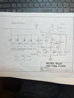
I Measured voltages in the relay circ rel to GND and see attached.
I noticed with the M2X certain of the input cards had more turn off thump than others and tried a norwood card and turn off thump was the same. Music sounded great though.
So not sure what to pursue next.
1. Is issue with tuba and possible wrong part installed? But works great and voltages fine just the turn off issue.
2. Could this be issue with the switch? Should this be replaced? Does a DC supply like this need a cap as does a conventional supply? Can arcing be a problem?
3. As I was one of the builders who was concerned with thump issue when I first built my VFET was grateful and excited to have this option with the added benefit of "dual mono" voltage regulated supply! Could this the issue with the output stage somehow? Although again functions great and sounds great.
4. As to not appeal only to Mark should I also post this to the VFET or Theseus Thread?
5. Pics of Nimitz show a bonehead error with 330 ohm Resistors instead of the 330k ohm resistors. Those have been replaced and the amps behavior is noted above. Didn't change the Turn off thump.
Thanks. The M2X cards have been such a revelatory experience want to have them in this gem. Also have a Dreadnaught built and waiting testing. Just want to resolve this issue first. Thanks
The start up thump was not audible with a 10 sec delay although I had the DC offset started about 15mV at relay click and climbed to 852mV as per my Fluke 87 min max function. Offset slowly declined over several min to 3-4 mV. There was NO turn ON thump. Music was great.
THE problem is I have big Turn OFF Thump. It is 85dB as per my SPL meter on audiotools on iphone. Measures as per my Fluke at 667 mV Right channel and 527 mV on left channel using min max function at speaker terminals.
I Measured voltages in the relay circ rel to GND and see attached.
I noticed with the M2X certain of the input cards had more turn off thump than others and tried a norwood card and turn off thump was the same. Music sounded great though.
So not sure what to pursue next.
1. Is issue with tuba and possible wrong part installed? But works great and voltages fine just the turn off issue.
2. Could this be issue with the switch? Should this be replaced? Does a DC supply like this need a cap as does a conventional supply? Can arcing be a problem?
3. As I was one of the builders who was concerned with thump issue when I first built my VFET was grateful and excited to have this option with the added benefit of "dual mono" voltage regulated supply! Could this the issue with the output stage somehow? Although again functions great and sounds great.
4. As to not appeal only to Mark should I also post this to the VFET or Theseus Thread?
5. Pics of Nimitz show a bonehead error with 330 ohm Resistors instead of the 330k ohm resistors. Those have been replaced and the amps behavior is noted above. Didn't change the Turn off thump.
Thanks. The M2X cards have been such a revelatory experience want to have them in this gem. Also have a Dreadnaught built and waiting testing. Just want to resolve this issue first. Thanks
Attachments
Well perhaps I might have had too great of expectations. Having reread the the VFET threads and Marks response in this thread
"Post photographs of your power on/off switch and its connection to your SMPS filter PCB. Are you using a 2-pole switch having four or more terminals?
I have seen at least four possible "turn off thump reduction" techniques for the N-channel VFET amplifier, discussed on these Forums.
1. The one designed by Nelson Pass and included in the N-channel VFET kit, on its SMPS filter PCB
2. The one called "Theseus PSFILT", whose PCB Gerber files are freely downloadable at LINK_1
3. The one called "Tuba", whose PCB Gerber files are freely downloadable at LINK_2
4. The Zen Mod redesign which asks you to modify your existing Nelson Pass PCB (cuts + jumps + new components), discussed at LINK_3"
I think I'll try living with it or try the two switch solution. Might change out the switch first and likely will be a good reason to also try the PSFILT and see if tuba or PSFILT makes any difference in subjective sound.
Or the ultimate solution might be to just leave it on all the time. 😊
It is surprising to learn that your Tuba-powered amp has a thump at turn-off. If you look at the circuit schematic (attached to #166 above) you'll see that the on-off switch directly and immediately removes the 653-G2R-24-DC24 relay's coil current (through connector J13). When the relay coil current immediately disappears, this causes the relay's armature to release within 5 milliseconds according to the relay's (datasheet). When the armature releases, the relay contacts short out the loudspeakers. So if the board is working correctly and wired up to the switch and to the speakers correctly, you are getting a turn-off thump in the first 5 milliseconds after the switch event. That's unexpected and surprising.
I'd recommend that you disconnect the SMPS from the amp (unplug the DIN connector), wait 60 seconds, and then carefully verify that the on-off switch is wired to the Tuba board correctly. Verify both poles of the switch. Check both ends of all wires visually, and double-check with your DVM on continuity test "buzz" mode. Also verify that when the switch is in its "off" position, the two pins of connector J13 do not have continuity. They are an open circuit.
Then carefully verify that the speaker terminals are wired to the Tuba board correctly. Check both ends of all wires visually and double-check with buzz testing. Also verify that each pair of speaker binding posts is solidly shorted together by doing an ohmmeter test instead of a buzz test. It should read 0.0 ohms.
My cousin Jimmy Jim-Bob Boudreaux, who lives in Fordyce Arkansas, would probably suggest that you consider temporarily trying a voodoo experiment. He'd say maybe it might help and certainly it can't hurt. Temporarily add at least 330 microfarads more capacitance between CH1_V+ and GND, and another same size cap between CH2_V+ and GND. 50 volts rating or higher. Maybe just using alligator clips and masking tape to insulate everything. Why would he pick that number of microfarads? Because it's ten times greater than what's on the board right now. If 33 is too small, 330 is likely to tell you so.
Last edited:

Thanks for the helpful and thoughtful response. I've become more comfortable with the Jenga VFET Chassis. Still is the most time consuming part of this debug. My usual algorithm for solving these problems is as follows
1. Whisper sweet words of encouragement into the gate of a mosfet.
2. Lightly caress the least warm component in an amplifier.
3. Voodoo.
4. Call Jim-Bob and usually a bigger hammer.
5. Search for any post of Nelson's that has phrase, "works like glue"
As I have the TUBA out for further testing. Have revised the board that came with the kit and used the Zen Mod redesign with the various cuts, and parts. Haven't been able to test with the amp portion yet. I do notice that the CIT relay doesn't seem to have audible click. Search of prior threads didn't have hits for click. I assume relay is fine just not audible like the G2R. Also seems that the time till relay click on start up as per your cal was 2.9 sec for the CIT.
Will try the larger capacitance with the TUBA and see what happens. Have spent some time trying to figure out how to use my oscilloscope to trigger with switch and them measure the time till relay shorts speaker output to ground, but that level of familiarity with my scope is lacking. Think that this issue will provide a nice experiment to see if I can discern any audible differences with the "dual mono" Tuba vs the "original ZM modification" when I get this figured out. Have built enough of these projects to realize that in the face of many other successful builds by others that the problem is somewhere in my sandbox.
Thanks.
Another Tuba up and running in a Sony N-VFet. Works like a charm.
I had boards produced using the gerbers in Post #1 with 70m um (2 oz) copper, per Mark's suggestion.
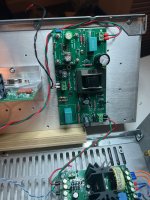
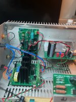
I didn't have any troubles getting 2.0 V across the regulator, although as predicted after connecting it to the amplifier the voltage dropped (in my case to about 1.5 V). I let the whole thing soak and adjusted the voltage up a few times - after an hour or so the VFet was 'warm' and I didn't note any more fall off. I also reset the drain voltage on the P-mosfet because it too had fallen off a bit (13.8 V rather 14.0 V). After that everything seemed pretty stable. Here is a picture of the internals:

There is no thump at all (now) and the timing circuit is just about bang-on on the 5 second delay.
Too, I was surprised and delighted by the improvement in channel separation and imaging with Tuba installed. Not a night-and-day improvement but more than simply noticeable.
Someday I'll try a new front end card and clean up the wiring a bit while I am in there.
This is a good piece of kit, and for those with VFet amps its a worthwhile upgrade for a fairly modest price. I'll probably put the extra boards from my PCB order in the Swap Meet sometime soon for those who might be interested.
Thanks Mark - this is a keeper.
I had boards produced using the gerbers in Post #1 with 70m um (2 oz) copper, per Mark's suggestion.
I didn't have any troubles getting 2.0 V across the regulator, although as predicted after connecting it to the amplifier the voltage dropped (in my case to about 1.5 V). I let the whole thing soak and adjusted the voltage up a few times - after an hour or so the VFet was 'warm' and I didn't note any more fall off. I also reset the drain voltage on the P-mosfet because it too had fallen off a bit (13.8 V rather 14.0 V). After that everything seemed pretty stable. Here is a picture of the internals:
There is no thump at all (now) and the timing circuit is just about bang-on on the 5 second delay.
Too, I was surprised and delighted by the improvement in channel separation and imaging with Tuba installed. Not a night-and-day improvement but more than simply noticeable.
Someday I'll try a new front end card and clean up the wiring a bit while I am in there.
This is a good piece of kit, and for those with VFet amps its a worthwhile upgrade for a fairly modest price. I'll probably put the extra boards from my PCB order in the Swap Meet sometime soon for those who might be interested.
Thanks Mark - this is a keeper.
Congratulations on a tight and tidy build! Very lovely.
If you ever do decide to build a new front end card, (this post #329 in another thread) makes a recommendation.
If you ever do decide to build a new front end card, (this post #329 in another thread) makes a recommendation.
- Home
- Amplifiers
- Pass Labs
- Tuba SMPS filter: two linear regulators inside VFET/Theseus chassis; incl thump kill