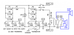
You need [ (potentiometer at max setting) + R2 ] to be 3.7 Kohms or a little higher. One way to achieve that is to replace the 1K potentiometer with a 2K potentiometer. Then you can drop R2 down to 1.7 Kohms (or a little higher, perhaps 2.2 Kohms).
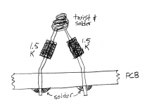
Another way to achieve this is to replace R2 with a pair of 1.5K resistors (0.3W or greater) in series, as shown in the diagram below. Then you can keep the 1K potentiometer, since (1.5K series 1.5K series 1.0K) is 4.0K --- and 4.0K meets the requirement stated in paragraph 1.
_
Another way to achieve this is to replace R2 with a pair of 1.5K resistors (0.3W or greater) in series, as shown in the diagram below. Then you can keep the 1K potentiometer, since (1.5K series 1.5K series 1.0K) is 4.0K --- and 4.0K meets the requirement stated in paragraph 1.
_
Attachments
Thanks Mark,
ok, the resistance value is now clear, both together about 4k.
In the part list was for R2 0W6 listed and in you post now > 0W3 so I take a look In my parts box and found 2k67 / 0W4 ... seems the be now all ok. 😎
ok, the resistance value is now clear, both together about 4k.
In the part list was for R2 0W6 listed and in you post now > 0W3 so I take a look In my parts box and found 2k67 / 0W4 ... seems the be now all ok. 😎
Hi Mark,
just wanted to say thank you, the first test on the workbench works great.
The two voltages can be set without any problems and the relay "clicks" as desired in all the delay positions.
I will observe the voltage later when VFET #16 is assembled and correct it according to your instructions (fine tuning).
Best regards ...Carsten
Two 1.5K 0.3 watt resistors in series, create a single 3.0K resistor which can dissipate 0.6 watts. 0.3 watts in the first 1.5K resistor, and another 0.3 watts in the second 1.5K resistor.In the part list was for R2 0W6 listed and in you post now > 0W3 so I take a look In my parts box and found 2k67 / 0W4 ... seems the be now all ok. 😎
A single 2.67K rated 0.4 watts is insufficient.
Congratulations! You may want to also review the LD1084 datasheet's figures 24 and 26. They might indicate it'd be a good idea to look at the output voltage waveform on an oscilloscope, when drawing an ampere of load current and having the big cap(s) on the output.
My first Tuba build. Tested fine as both voltages were easily set to 2V and were rock steady. It will go in my P1 VFET after I have the build complete and listened to for comparison. The build was fun and packed with detail.
Thank you Mark for the project. I also built Nimitz which I am excited about but a couple Norwood parts are a couple months out.🙁 I want to hear Norwood in the VFET as I like it best in the M2x. And, am apparently not alone there.
Don


Thank you Mark for the project. I also built Nimitz which I am excited about but a couple Norwood parts are a couple months out.🙁 I want to hear Norwood in the VFET as I like it best in the M2x. And, am apparently not alone there.
Don

Is this one of the graphs you were refering to? With an output voltage of 12V, the ESR is stable from 1uF to 100uF. If you can point me to it's relevance I would appreciate it.Congratulations! You may want to also review the LD1084 datasheet's figures 24 and 26. They might indicate it'd be a good idea to look at the output voltage waveform on an oscilloscope, when drawing an ampere of load current and having the big cap(s) on the output.
Attachments
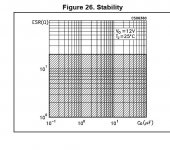
That's a plot of the (in)stability of the LD1084 itself. For some (Capacitance, ESR) combinations, the LD1084 is unstable. It's a shame that ST Microelectronics didn't label the figure to tell you whether the dark shaded region is stable or unstable. Might want to check with an oscilloscope, while drawing an ampere of load current.
TI sells what appears to be the same device, which they call LM1084. Its datasheet doesn't include stability plots, but it does include a section called 7.4 which talks about stability.
TI sells what appears to be the same device, which they call LM1084. Its datasheet doesn't include stability plots, but it does include a section called 7.4 which talks about stability.
Wow, thanks. Appreciate the compliment. I did put my best into it as I thought it deserved it.Congratulations on a successful and extremely tidy build!!
Started wiring the amp yesterday and decided to jump right to the Tuba. Doesn't make much sense to me to solder everything under the sun and have all these front end options. This isn't like the daughter cards on the M2x. Another benefit to Tuba.
Don
I finished my VFET amp here - https://www.diyaudio.com/community/threads/diy-sony-vfets-pt-3-got-vfets.381181/post-7126904
Apologies if this is already stated somewhere but got a quick question on the usage of the Tuba smps filter board. I see that it has 2 pins on the output side marked SPKR_01_02 from the relay and I could not find its usage from the posts or I am missing something. When I use these pins as output speaker binding posts ground and after the relay clicks I do not get any sound but when I connect the binding post ground directly from the amp ground I get the music fine but their is a good amount of thump when I switch off the amp. I need some wiring directions of how to use the SPKR_01_02 to get rid of the turn off thump.
Thanks in advance.
In post#1 of this thread, I wrote
The N-channel VFET supply filter board is shown on page 3 of the article on First Watt's website: here is the pdf. Nelson's diagram and guide to wiring up the supply filter is shown on page 5 of that pdf.
Nelson's schematic labels the right speaker's binding post "O1" and labels the left speaker's binding post "O2". These correspond to "SPKR_OUT1" and "SPKR_OUT2" on the Tuba schematic.
Nelson's thump elimination idea, which I copied for Tuba, is to short the speaker terminals to ground during power-up and power-down. Because the VFET design connects a big electrolytic coupling capacitor in series between the amp and the speaker load, no DC current can flow -- not even when the speaker is shorted out by the relay contacts.
_
There is also a thump prevention relay circuit, on page 2 of the schematics. It is just a slightly fancier implementation of the thump preventer on the N-channel VFET supply filter board, designed by Nelson Pass. The same two-pole switch ("DPST") from the Nch VFET filter board is used. One pole turns power on and off, the other pole gives the thump preventer circuit a warning that the supply is about to collapse Right This Moment.
... ... ...
Because Tuba is a project for advanced hobbyists only, there isn't much more documentation than you see here; no "training wheels" build guides or Mouser shipping carts or troubleshooting tutorials. If you think you need those, maybe Tuba isn't the right project for you just yet.
The N-channel VFET supply filter board is shown on page 3 of the article on First Watt's website: here is the pdf. Nelson's diagram and guide to wiring up the supply filter is shown on page 5 of that pdf.
Nelson's schematic labels the right speaker's binding post "O1" and labels the left speaker's binding post "O2". These correspond to "SPKR_OUT1" and "SPKR_OUT2" on the Tuba schematic.
Nelson's thump elimination idea, which I copied for Tuba, is to short the speaker terminals to ground during power-up and power-down. Because the VFET design connects a big electrolytic coupling capacitor in series between the amp and the speaker load, no DC current can flow -- not even when the speaker is shorted out by the relay contacts.
_
Attachments
Thanks @Mark Johnson now I get that from Nelson's PDF doc with the page #5 wiring diagram which I completely missed reading about it thinking its only for N channel and I build the P channel 🙂
So based on this wiring diagram I just now need to put wiring from the output (O+) on the amp to the Spkr_01 and from Spkr_01 run another wire to the speaker binding post positive with the speaker binding post ground being common from the ground of the amp board. Switch p2 I have shorted as using only switch p1 with the front panel on/off button. I need to do the same with the other channel too using spkr_02 👍
Thanks
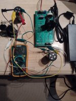
I just finished my VFET build with the tuba PS filter. Picture attached sans thump kill wiring. Everything worked perfectly out of the box. Thanks Mark. This brings us to the elephant in the room question. Why not just buy MeanWell SMPS supplies and pair them with Tuba filters for all the builds. Seems much simpler than dealing with transformers, rectifiers/bridges, filters, thump cut-offs, etc. Kind of one size fits all.
Will the Tuba's handle a variety of voltages?
This was sooo... easy. 36V in, 34V out. One setting/channel. The VFET outputs took less than a 1/4 turn and they dialed in to a perfect 20V. Actually, I think I took the easy road and left them at 20.04V each.
Is there something I am missing?
Anyway, thanks for the filter Mark
That's an extremely clean build, contratulations @donhughes111 !! Do you also have a photo showing the Tuba thump-muting terminals "SPKR_01" and "SPKR_02" connected somewhere and not simply floating ?
No pic on that - yet. The speaker signal wires are customized with a shield because of my audio nervosa with powered signals running through the box near a bunch of other wires. Kind of thinking through best way to do the connection. I plan on tackling that when I convert the front end to the Nimitz with Norwood. Norwood parts are sloooow. Supposed to have them by mid month. The thump really isn't too bad on my system. My amp is the P-channel.That's an extremely clean build, contratulations @donhughes111 !! Do you also have a photo showing the Tuba thump-muting terminals "SPKR_01" and "SPKR_02" connected somewhere and not simply floating ?
- Home
- Amplifiers
- Pass Labs
- Tuba SMPS filter: two linear regulators inside VFET/Theseus chassis; incl thump kill