I am building this 3 way for my desktop. I am sure some of you have seen my previous posts.
The main build thread is here: https://www.diyaudio.com/community/...ffice-build-thread.421776/page-2#post-7890664
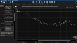
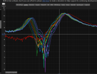
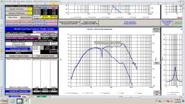
Can someone take a whack at notching out this 340 hz peak for me? I will attach the full data packet
I am having zero success notching out this 340 hz peak in the woofer response. This is a cause of the port resonance which is, itself, the cause of me crossing the woofer at 800 hz.
I have tried 4 different port designs and about 20 different Heimholtz resonators. I am able to kill it with heimholtz resonators but I would need 6-7 of them attached to the port for it to actually work. The Heims cause their own issues. Details of that in the thread.
My notch filter skills are minimal at best. I honestly haven't run into any super problematic issues like this to require me to develop said skills. I know how to make a basic one with a cap, an inductor, and a resistor. I tired both in series and in parallel. Neither seemed to work. I tried some notch filter calculators that used more elaborate notches but those did not work either. 3 hours in. I am asking for help.
I very much appreciate any help as always. Thank you in advance for trying, even if you do not succeed.
The main build thread is here: https://www.diyaudio.com/community/...ffice-build-thread.421776/page-2#post-7890664
Can someone take a whack at notching out this 340 hz peak for me? I will attach the full data packet
I am having zero success notching out this 340 hz peak in the woofer response. This is a cause of the port resonance which is, itself, the cause of me crossing the woofer at 800 hz.
I have tried 4 different port designs and about 20 different Heimholtz resonators. I am able to kill it with heimholtz resonators but I would need 6-7 of them attached to the port for it to actually work. The Heims cause their own issues. Details of that in the thread.
My notch filter skills are minimal at best. I honestly haven't run into any super problematic issues like this to require me to develop said skills. I know how to make a basic one with a cap, an inductor, and a resistor. I tired both in series and in parallel. Neither seemed to work. I tried some notch filter calculators that used more elaborate notches but those did not work either. 3 hours in. I am asking for help.
I very much appreciate any help as always. Thank you in advance for trying, even if you do not succeed.
Attachments


I can just seal it and then this problem goes away. So does the 30 hz bass response though. If I can fix this then I'll run the port. If not, I'll seal it and rely on the gigantic push-push coffee table / subwoofer.18mh coil? Oof. The spike is so narrow, it's a bit hellish for a passive notch. No disrespect, your dedication and 3d printing skills are amazing, but frankly, had you not just considered doing a conventional box shape, even if it solves problems like this?
I do want it to be standalone so if I even want to move it elsewhere it can hold its own full frequency
Well its a lot better than what I could do. That's huge inductor. Still, better.
Is there a way to make it even more narrow so it affects just the peak? Its pulling down a lot with it between 200-500 hz. That is the trouble I had with it.
I wish I could cross it higher but the planar mid basically gives up after 800. It will still play but then we're into a few percent of distortion. The epique has incredibly low distortion all the way up to like 2k. The response gets erratic but it plays cleanly. The same cannot be said for the planar though that plays crazy clean within its dedicated 800-5k bandwidth.
Attachments

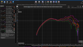
It's not that simple, unfortunately. As you can see here looking at the notch on it's own, there's a dip right beside it which gets mixed up into it.

I'd look at the excellent work of member @stv who has a thread on port resonance.
https://www.diyaudio.com/community/...sonance-absorbers-and-port-geometries.388264/
I'd look at the excellent work of member @stv who has a thread on port resonance.
https://www.diyaudio.com/community/...sonance-absorbers-and-port-geometries.388264/
I read that thread. I tried the heimholtz resonators. I did not try to the tubes. I may have to just send him a message. My only experience with dealing with these sorts of resonances is on race cars. It doesn't seem to have the same effects on a port as it does on a race exhaust.I'd look at the excellent work of member STV who has a thread on port resonance.
Lower XO may just work.....
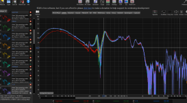
After posting the distortion graph I took a harder look at that mid data. Maybe playing it a bit lower wouldn't be such a bad idea. I have found that the further you can cross outside of the vocal band, the better.
After posting the distortion graph I took a harder look at that mid data. Maybe playing it a bit lower wouldn't be such a bad idea. I have found that the further you can cross outside of the vocal band, the better.
Attachments
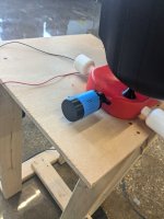
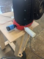
You could try a small helmholtz resonator tuned to the peak, opposite or near the enclosure end of the port. My version here.I tried the heimholtz resonators.
Attaching a resonator-absorber at half port length can reduce the resonance peak a lot, but it has the disadvantage of additional air turbulence. You can avoid that by separating port and resonator with a thin membrane. My experiments here.
Try dividing the inductor by 4 and multiplying the capacitor by 4 (therefore same notch frequency but different Q) play with the resistor value and see what happens. May make it worse, may work.
Also instead of LCR all in series wired in parallel with the driver, try LCR in parallel, wired in series with the driver.
I’m concerned that the first LCR option gives you a deep impedance dip.
Also instead of LCR all in series wired in parallel with the driver, try LCR in parallel, wired in series with the driver.
I’m concerned that the first LCR option gives you a deep impedance dip.
I maxxed out the stuffing. This did greatly improve the issue. It used to be even worseI would investigate woofer cabinet stuffing, before resorting to any rlc's.
Yes I tried a lot of those. I was going to ask you about yours.You could try a small helmholtz resonator tuned to the peak, opposite or near the enclosure end of the port. My version here.
Attaching a resonator-absorber at half port length can reduce the resonance peak a lot, but it has the disadvantage of additional air turbulence. You can avoid that by separating port and resonator with a thin membrane. My experiments here.
The issue I ran into was that you do kill that main resonance peak but then two nasty peaks show up on either side. Is there a certain ration of neck volume to main internal volume that widens the working band or doesn't cause these peaks?
I have added up to 3. The main one the main port resonance peak with the other two killing the two peaks caused by the first heimholtz resonator. I just kept going around in circles so I stopped.
I did also try stuffing them but all that does is lower the effective resonance of the heimholtz resonator itself. Which is as expected.
Do you know what I'm doing wrong that I'm getting these additional peaks either side? The way I see it now, I would need around 6 heimholtz resonators to kill this whole thing.
Attachments
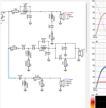
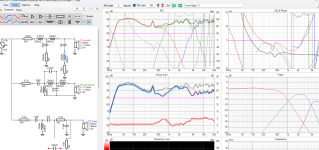
I did not use your files to sim this, but try it with yours. The notch is a resistor, a .2mH coil, and a 1000uf cap. The notch frequency seems to stay the same while other x-over values are changed. If you need even sharper notch make the coil .15mH, and the cap larger. The 20 ohms resistor can be decreased down to about 5 ohms if the notch is too effective.
This notch is before the rest of the woofer x-over. I played with the other values to see the shape near the notch and the impedance. So, the 2 ohm shown after the 65uf cap is not something required. It did alter the response up close to the notch I think. Impedance seemed fine.
This notch is before the rest of the woofer x-over. I played with the other values to see the shape near the notch and the impedance. So, the 2 ohm shown after the 65uf cap is not something required. It did alter the response up close to the notch I think. Impedance seemed fine.
Attachments
Last edited:
I had very similar experiences!The issue I ran into was that you do kill that main resonance peak but then two nasty peaks show up on either side. Is there a certain ration of neck volume to main internal volume that widens the working band or doesn't cause these peaks?
Generally a helmholtz absorber/resonator has a more narrow peak than a simple quarter wave lenght tube resonator (anyone correct me if i am wrong!).
There is a gliding transition from helmholtz resonator to tube resonator.
As far as I know bigger enclosures with long narrow ports/tubes have the most pronounced narrow peaks.
Therefore I concentrated on wider absorption range tube resonators with quarter wave length tuning.
I used a bike air pump and a syringe to build variable lenght absorbers for testing. here is an animated GIF with varying absorber length.
Click on the image for animation!
And I had the best results without the two "sideband" peaks by filling the interior half of the resonator with melamine foam ("dirt eraser sponge" or basotect), see this post.
I the response graphs of the latter posting you can see the two resonance peaks and how they disappear when using melamine foam in the resonator.
Last edited:
Well at least I'm not alone, nor am I doing it wrong.Generally a helmholtz absorber/resonator has a more narrow peak than a simple quarter wave lenght tube resonator (anyone correct me if i am wrong!).
There is a gliding transition from helmholtz resonator to tube resonator.
As far as I know bigger enclosures with long narrow ports/tubes have the most pronounced narrow peaks.
So the pipes, we call these "j pipes" in the race car world, have a wider absorption range.Therefore I concentrated on wider absorption range tube resonators with quarter wave length tuning.
I used a bike air pump and a syringe to build variable lenght absorbers for testing. here is an animated GIF with varying absorber length.
Click on the image for animation!
Is there a calculator to figure out the length and the cross section? Or a formula I can use. This seems like the logical next step for me to try.
Very clever using the syringe for a variable length pipe. I feel like I could use one 3d printed tube inside another, then slide it to the length I need sort of like a trombone.
I have some melamine foam sitting on a shelf right now. I could try it no problem. Do you think it would work with the heimholtz resonators the same way it did with your J pipes? Or is only with the J pipe that it works?And I had the best results without the two "sideband" peaks by filling the interior half of the resonator with melamine foam ("dirt eraser sponge" or basotect), see this post.
I the response graphs of the latter posting you can see the two resonance peaks and how they disappear when using melamine foam in the resonator.
I am not finding anywhere to purchase Basotect from. Where did you source yours?
Didn't workI did not use your files to sim this, but try it with yours. The notch is a resistor, a .2mH coil, and a 1000uf cap. The notch frequency seems to stay the same while other x-over values are changed. If you need even sharper notch make the coil .15mH, and the cap larger. The 20 ohms resistor can be decreased down to about 5 ohms if the notch is too effective.
This notch is before the rest of the woofer x-over. I played with the other values to see the shape near the notch and the impedance. So, the 2 ohm shown after the 65uf cap is not something required. It did alter the response up close to the notch I think. Impedance seemed fine.
Attachments
- Home
- Loudspeakers
- Multi-Way
- Seeking Notch Filter Help