Still doesn't work quite right. Are you suggesting this to replace the entirely of the current filter? The impedence of the driver will throw off the values considerablyI don't see it in the above post. This is what I'm suggesting.
Attachments

One more question: Is the pipe resonator you used open at the one end or is it closed at both ends?I had very similar experiences!
Generally a helmholtz absorber/resonator has a more narrow peak than a simple quarter wave lenght tube resonator (anyone correct me if i am wrong!).
There is a gliding transition from helmholtz resonator to tube resonator.
As far as I know bigger enclosures with long narrow ports/tubes have the most pronounced narrow peaks.
Therefore I concentrated on wider absorption range tube resonators with quarter wave length tuning.
I used a bike air pump and a syringe to build variable lenght absorbers for testing. here is an animated GIF with varying absorber length.
Click on the image for animation!
And I had the best results without the two "sideband" peaks by filling the interior half of the resonator with melamine foam ("dirt eraser sponge" or basotect), see this post.
I the response graphs of the latter posting you can see the two resonance peaks and how they disappear when using melamine foam in the resonator.
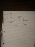
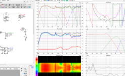
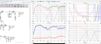
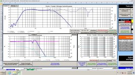
This is a sim using your woofers files. I only worked with the woofer. This filter is the entire woofer filter, and not to be added to other woofer filter parts.
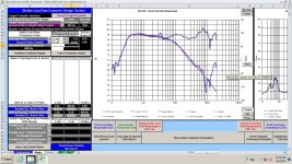
Here's the response. I was shooting for 4th order. I can adjust for a 2nd order if needed. The notch portion is likely almost the same. The notch portion is the three parts on the left side in my hand drawn sketch.
Here's the response. I was shooting for 4th order. I can adjust for a 2nd order if needed. The notch portion is likely almost the same. The notch portion is the three parts on the left side in my hand drawn sketch.
Attachments

Length is exactly half of the port length.Is there a calculator to figure out the length and the cross section?
The port has two open ends and is a half-wavelength resonator. The absorber has the exterior end clised and is a quarter wavelength resonator/absorber.
Diameter that worked for me was about 2-3 cm, at a length of 11 and 5.5 cm.
I got some leftovers from a foam supplier.I am not finding anywhere to purchase Basotect from. Where did you source yours?
But I found a very cheap version called "dirt eraser foam", available at the drugstore. Search for "magic eraser sponge" on amazon or similar.
Maybe its been a long day but I am not visualizing what you are saying here. Do you have a picture? The only picture I saw in the thread was the menagerie of tubes when you were doing the syringe testing. I'm a visual person so pictures help me a lot.Length is exactly half of the port length.
The port has two open ends and is a half-wavelength resonator. The absorber has the exterior end clised and is a quarter wavelength resonator/absorber.
Diameter that worked for me was about 2-3 cm, at a length of 11 and 5.5 cm.
I also have magic erasers.But I found a very cheap version called "dirt eraser foam", available at the drugstore. Search for "magic eraser sponge" on amazon or similar.
I put the melamine foam inside one of the heimholtz resonators just to see what it would do. Interestingly, it makes them 100% ineffectual. Once filled with foam, even lightly, they don't have any measurable effect on the frequency response of the port.
Do you have a picture?

Port length is just my guess, based on the 340 Hz peak. The absorber tube should have half the port length.
Of course the tube does not have to protrude at 90 degrees from the port, as shown here. But it needs to be located at the middle of the port length for good effectivity.
Last edited:
Totally get it now. That makes sense. I will try this out and let you know how it goes.Port length is just my guess, based on the 340 Hz peak. The absorber tube should have half the port length.
Of course the tube does not have to protrude at 90 degrees from the port, as shown here. But it needs to be located at the middle of the port length for good effectivity.
Do you think moving the port entrance to the other side of the enclosure would help? Is this a standing wave or definitely a result of the port geometry? I figure you're the best one to ask
Attachments
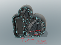
I doubt that.Do you think moving the port entrance to the other side of the enclosure would help?
It's most likely the port - unless your port length is very different than I estimated.Is this a standing wave or definitely a result of the port geometry?
Did you try to simulate the enclosure in hornresp? Hornresp models the port resonances very accurately.
I did. It shows the hump almost exactly as it appears in real life.Did you try to simulate the enclosure in hornresp? Hornresp models the port resonances very accurately.
I was just hoping there was a chance I could just move it and all would be fine......... even though the logical part of my brain knows it's a facet of the design.
I am printed out some variable length tubes. I can try them out tomorrow with the melamine fiam and magic eraser material.
The whole enclosure needs to get reprinted. I will end up with slightly less internal volume so I will have to take all the measurement again. This print takes 58 hours
Yes, I did. I tried it, it did not workDid you even look at the notch filter I posted? It totally eliminates the peak.
Attachments

In this case you could reprint with a more flared port and by doing so reduce the port length and eventually push the port resonance out of the woofer pass band.The whole enclosure needs to get reprinted.
Let me know if that seems viable for you. I could use your enclosure as an example for SPL related dimensioning of an "ideal" port.
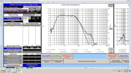
The filter I suggested will work, according to my sim. It has 5 parts, not the 8 or more you show in your sim. That sim does not work. Notch filters can be weird. This one needs to be in front of the rest of the filter.
Try this in your sim on the woofer only, with nothing else on the woofer, and see if it works . If I used Xsim, I'd show you myself. The PCD sim I posted shows that it works.
On the down side, you probably don't have room for the big caps anyway.
This is what should show on the woofer filter. No additional parts needed. The roll-off might not be what you want, but the spike in response is gone.
Also.... I do not know what power rating might be needed on the resistor. It might get very hot. I think your software can predict that information. I've never used a filter like this, but if I did, I'd be checking the resistor to see if it heats up frequently.
Last edited:
The figures a bit fuzzy for my eyes to read... impedance 10ohm at 330hz?
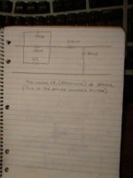
@temp25 May I suggest 45uF || 5mH || 10R. A notch around 330hz should indeed multiply uF*mH~225 (because frequency~5khz/sqrt(uF*mH) see below math) but the filter values 900*0.25 would run past each other.
@temp25 May I suggest 45uF || 5mH || 10R. A notch around 330hz should indeed multiply uF*mH~225 (because frequency~5khz/sqrt(uF*mH) see below math) but the filter values 900*0.25 would run past each other.
o simplified formula for 1st-order XO -6dB per octave i.e. halved (driver impedance in ohm)
high-pass-filter=-3dB@(160khz/imp)/uF
low-pass-filter=-3dB@(160hz*imp)/mH
(e.g. imp=8 HPF@20khz/uF LPF@1280/mH, typically set to equal before tweaking by ear
o if the full-range driver reaches high enough but has a resonance peak (tyically ~5-7khz) or otherwise needs to be "tamed", the simplest notch filter is to treat it as two virtual parallel drivers, and connect both HPF and LPF (in parallel) to speaker + pole (so-called in series), the XO frequencies being unequal so as to sum (precisely and predictably) to a notch at the resonance peak
o if the above-formed notch valley is detectable by ear (using the APP), add a series-chain of resistors in parallel with HPF and LPF to in-fill the notch
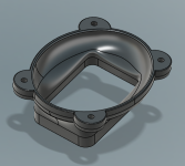
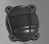
I can try to clean this up a bit. How much more of a flare would I need do you think?In this case you could reprint with a more flared port and by doing so reduce the port length and eventually push the port resonance out of the woofer pass band.
Let me know if that seems viable for you. I could use your enclosure as an example for SPL related dimensioning of an "ideal" port.
Are the resonances mainly based on port length? I could try shortening the port. I don't really need it to hit to 30 hz but figured "why not" when the driver will happily do it.
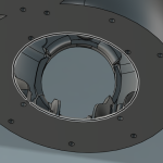
I will post picture of the flare I have. Its not so easy to design this since they need to be printable and they need to mate up as two pieces. I also have the design constraint of it needing to fit underneath my overhead monitors.
I'll remind that hand drawn pictures help me out a lot.
BTW, will be testing the tube today. I have a variable length 20mm tube printing out right now.
Attachments

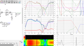
Try and see what happens to it if you add the rest of the filter though. The components have effects on one another.Here's the results of MY sim. It doesn't get much better than this.
Attachments

The XO will be located exterior to the enclosureOn the down side, you probably don't have room for the big caps anyway.
- Home
- Loudspeakers
- Multi-Way
- Seeking Notch Filter Help