I tried it again. Similar result.The filter I suggested will work, according to my sim. It has 5 parts, not the 8 or more you show in your sim. That sim does not work. Notch filters can be weird. This one needs to be in front of the rest of the filter.
Try this in your sim on the woofer only, with nothing else on the woofer, and see if it works . If I used Xsim, I'd show you myself. The PCD sim I posted shows that it works.
On the down side, you probably don't have room for the big caps anyway.
This is what should show on the woofer filter. No additional parts needed. The roll-off might not be what you want, but the spike in response is gone.
Also.... I do not know what power rating might be needed on the resistor. It might get very hot. I think your software can predict that information. I've never used a filter like this, but if I did, I'd be checking the resistor to see if it heats up frequently.
View attachment 1404273
What sim software are you using? I am totally aware that VituixCAD is not the perfect sim software
Attachments
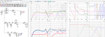
I don't know why it doesn't work in your software. It does look like you connected it right in post #41 above . Why is the line blue right after the notch? Does a blue line mean something different than if it was a black line? I won't continue saying the notch works. You can try PCD if you like.
Edit. Here's the reason maybe. You have virtually a dead short in the padding to your mid in the above schematic. You need to change that even without a notch.
Here's a link to the software.
http://audio.claub.net/software/jbabgy/PCD.html
Edit. Here's the reason maybe. You have virtually a dead short in the padding to your mid in the above schematic. You need to change that even without a notch.
Here's a link to the software.
http://audio.claub.net/software/jbabgy/PCD.html
Last edited:
The mid padding is not the problem. I shorted the mid in my sim, and nothing changed with the notch.
I am relying on a sim. If I didn't have the software, I would not have tried anything similar.
If I had enough caps, I could wire one up and see if it works. I may have enough caps on hand, but probably not enough jumpers.
I am relying on a sim. If I didn't have the software, I would not have tried anything similar.
If I had enough caps, I could wire one up and see if it works. I may have enough caps on hand, but probably not enough jumpers.
I wired it up on a speaker, and it does not appear to do anything. 😕 There's a chance I have a bad jumper wire, or shorted cap, but I'm assuming that it just doesn't work.
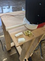
Ok, so I tried this out. I found the length that put me right on the money for hitting the peak. I then filled it with various material, only about 1/3 of it.Length is exactly half of the port length.
The port has two open ends and is a half-wavelength resonator. The absorber has the exterior end clised and is a quarter wavelength resonator/absorber.
Diameter that worked for me was about 2-3 cm, at a length of 11 and 5.5 cm.
I got some leftovers from a foam supplier.
But I found a very cheap version called "dirt eraser foam", available at the drugstore. Search for "magic eraser sponge" on amazon or similar.
Filling it with any material at all makes it not work. I tired rock wool, magic eraser, and melamine foam.
What am I doing wrong here?
Attachments

Definitely!Are the resonances mainly based on port length?
Your offset port looks interesting. Not sure if that introduces more turbulence or if it just lowers the longitudinal resonance.
I'll make another sketch showing a flared port.
It should probably look similar to this one.
Photo of 3d printed halves.
The middle cross section area can be 50% of the end cross section area without negative effects. This leads to a reduced total port length for the same tuning (nearly half the length).
As a result the unwanted rrsonance will be at higher frequency and lower in amplitude.
Last edited:
Is the absorber tube closed at the exterior end? (it has to be!)What am I doing wrong here?
Edit: I also noticed that below a diameter of 2.5 cm (1") the absorber did not work.
Filling broadens the absorption peak. If you don't need that it might just be ok to leave the tube empty!
Interesting. Might be hard to incorporate into this. With the port being the stand.Definitely!
Your offset port looks interesting. Not sure if that introduces more turbulence or if it just lowers the longitudinal resonance.
I'll make another sketch showing a flared port.
It should probably look similar to this one.
Photo of 3d printed halves.
The middle cross section area can be 50% of the end cross section area without negative effects. This leads to a reduced total port length for the same tuning (nearly half the length).
As a result the unwanted rrsonance will be at higher frequency and lower in amplitude.
Yes, it is.Is the absorber tube closed at the exterior end? (it has to be!)
Well I guess I need to make it much bigger then. The one I made was only 15mm in diameter. 1 inch is wayyyyy bigger.Edit: I also noticed that below a diameter of 2.5 cm (1") the absorber did not work.
So far, in my research, I have found that filling any of these devices either lowers their working frequency (I assume by making the volume effectively larger) or make it entirely useless where it has zero effect. I will try a much large opening and see how that goes.Filling broadens the absorption peak. If you don't need that it might just be ok to leave the tube empty!
I'll be honest, this is a lot failed tests in a row. It is quite disheartening.
What sim are you using?I wired it up on a speaker, and it does not appear to do anything. 😕 There's a chance I have a bad jumper wire, or shorted cap, but I'm assuming that it just doesn't work.
Sorry to hear that!It is quite disheartening.
Before continuing with bigger absorbers maybe try just perforating the port as roozen did in his tests, see chapter 6 in the pdf:
https://techtalk.parts-express.com/filedata/fetch?id=1457627
So its just drilling a bunch of little holes halfway down the tube and wrapping with foam? Worth a shot I guess. He's damping 2.2k and 1.1k hz resonances with that. I'm not sure it'll work on my beefy 340 hz. Can't hurt.Before continuing with bigger absorbers maybe try just perforating the port as roozen did in his tests, see chapter 6 in the pdf:
I'll print a 1" variable tube anyways. I have a huge stock of filament. I got rolls 1 kg rolls for $8 a pop during a black friday sale. I picked up 30 rolls specifically for prototyping stuff like this.
I tried several notches laid out as I suggested. Not even one worked! The software is actually pretty useful, but this must be a flaw in it. It may work for broad notches, but not for the tiny width notch I was shooting for here. Sorry it didn't work.What sim are you using?
If its any consolation, I have never once been able to successfully implement a narrow bandwidth notch filter.I tried several notches laid out as I suggested. Not even one worked! The software is actually pretty useful, but this must be a flaw in it. It may work for broad notches, but not for the tiny width notch I was shooting for here. Sorry it didn't work.
I swear they are a dark magic that requires selling a portion of one's own soul to master
I've not followed all the other things you tried Did you try altering the location of the port entrance inside the box?
Not yet. I am trying to avoid that at all costs. The current entrance is carefully placed above a center of gravity since the port is the stand.I've not followed all the other things you tried Did you try altering the location of the port entrance inside the box?
It also requires a $70 reprint of the back shell. I will have to do that but I'd rather not do it experimentally. Right now I cannot even print another back shell as the module that loads the filament into the printer is broken. That means I'm limited to 1000 gram prints. Even with minimal strength shell printing this will be over that
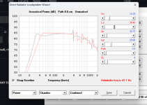
I suppose I never shared this date but it is peritinent to the current discussion.
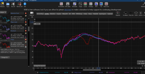
This is empty vs half stuffed vs stuffed with as much rockwool and poly as I could fit into the shell.
As you can see, it smooths out the upper range output of the port but it does absolutely nothing to my 340 hz problem child.
This is empty vs half stuffed vs stuffed with as much rockwool and poly as I could fit into the shell.
As you can see, it smooths out the upper range output of the port but it does absolutely nothing to my 340 hz problem child.
Attachments

Can you add an elbow inside that would move the port end even a few inches. It would add length.Not yet. I am trying to avoid that at all costs. The current entrance is carefully placed above a center of gravity since the port is the stand.
It also requires a $70 reprint of the back shell. I will have to do that but I'd rather not do it experimentally. Right now I cannot even print another back shell as the module that loads the filament into the printer is broken. That means I'm limited to 1000 gram prints. Even with minimal strength shell printing this will be over that
Technically I can add/subtract anything I want.Can you add an elbow inside that would move the port end even a few inches. It would add length.
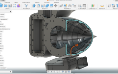
Are you talking about an elbow here so that the wave off the back of the driver doesn't go directly into the port?
If so, yes, I have thought of this. Even a plate would work too. Only issue I have with moving any part of the port inside is that it technically takes up enclosure space. Very precious and calculated enclosure space. I could probably print a prototype to fit in there without having to reprint the whole thing. Just to try it out.
Attachments
Playing with Hornresp I don't see exactly what I saw before but this is response. Its clearly way off on the low end. I do notice that it brings those nasty resonances forward if I move the LTC (rear chamber distance) further out.
Currently the back of the enclosure is about 30 cm back. I wonder if it is actually the circular shape causing that big resonance. It is possible
Anyone with some horn resp experience want to take a look?
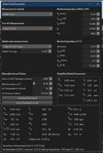
enclosure is currently 10.7 liters, port is 26 cm2, 18 cm long. I'll post the TS parameters. SD is 95cm2
Currently the back of the enclosure is about 30 cm back. I wonder if it is actually the circular shape causing that big resonance. It is possible
Anyone with some horn resp experience want to take a look?
enclosure is currently 10.7 liters, port is 26 cm2, 18 cm long. I'll post the TS parameters. SD is 95cm2
Attachments
Id admire your energy and creative design. I didnt want to give any opinion from the beginning with good intentions on this project.
Because I felt it would seem disrespectful. Only because of the creative energy and excitement you had.
Maybe the crossover points can be changed to help, but you run into bandwith issues. The classic magical shape, magical round small skinny baffle stuff make it 10x more work to get good responses. Already knew or figured you might have got this =

If this is the port, looks basically like the same folded velocity ramp, that is too big and too long.
Aka transmission line, or will basically behave like a transmission line. Which I affectionally call " resonant barf tubes"

Hopefully to get something from the project, again I admire your energy and fast work.
No magic foam, magic rubber, magic organic wool, rockwool or all the millions of things people meaning for absorption.
Hair like structure for pressure to pass through easily, but find friction = AKA poly fill, poly stuffing
Stuff the living heck out of the enclosure to reduce the round reflective surfaces. With poly fill, aka pillow stuffing. Dense very dense everywhere.
Then the port like any TL lines can pretty much be loose stuffing not too dense fill, but which still fills the cavity wall to wall.
With such a extra case of resonance stuff All the way down the tube. loose hair not dense rockwool. could likely glue felt to walls right at the entrance
Because I felt it would seem disrespectful. Only because of the creative energy and excitement you had.
Maybe the crossover points can be changed to help, but you run into bandwith issues. The classic magical shape, magical round small skinny baffle stuff make it 10x more work to get good responses. Already knew or figured you might have got this =
If this is the port, looks basically like the same folded velocity ramp, that is too big and too long.
Aka transmission line, or will basically behave like a transmission line. Which I affectionally call " resonant barf tubes"
Hopefully to get something from the project, again I admire your energy and fast work.
No magic foam, magic rubber, magic organic wool, rockwool or all the millions of things people meaning for absorption.
Hair like structure for pressure to pass through easily, but find friction = AKA poly fill, poly stuffing
Stuff the living heck out of the enclosure to reduce the round reflective surfaces. With poly fill, aka pillow stuffing. Dense very dense everywhere.
Then the port like any TL lines can pretty much be loose stuffing not too dense fill, but which still fills the cavity wall to wall.
With such a extra case of resonance stuff All the way down the tube. loose hair not dense rockwool. could likely glue felt to walls right at the entrance
- Home
- Loudspeakers
- Multi-Way
- Seeking Notch Filter Help