It all started nearly 20 years ago, when Gary Pimm introduced his push-pull 47 DHP amp to the audiophile community. I must've entered a mid-life crisis (which still shows no sign of abating) and decided that I had to build that.
I've assembled most of what was needed, except OPTs; PTs and chokes came from Peter Dahl of Texas (yes, I decided on monoblocks), and I talked Gary, who displayed an angelic patience in answering all of my idiotic questions, into building the CCS and servo boards for me.
Then I developed cold feet. Or, perhaps, some thing have their own timing and are guided by their own stars. I remember getting involved with vintage amps and doubting my talents to build something of equal quality. Also, I didn't have a reasonably efficient pair of speakers to match with the PP47, but now having built 3 pairs of Coral Holy Basket based speakers (one bookshelf and two Frugel horns), I told myself 'now is the time'.
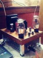
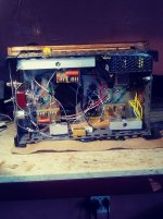
Gary's CCSs still have all the juice, and I'm following his advice to run it for a month before wiring in the servos. I'm using power switching supplies to feed DC to the 47s and finemet 14K OPT from Audiofeast/Terramoto which fit nicely under the chassis.
What can I say? My heavily modified Ampex 6973 monoblocks, the creme de la creme of vintage gear do not hold a candle to these PP47s. Which fills me with daring thoughts to sell the Ampexes along with a bunch of other gear and put the money toward a stereo version of PP47 ... Tabor perhaps ... SS Tabor (see the brazenness, and no, it shan't take two decades).
Anyway, here are the pics. And let's hope that they may trickle down to Gary's attention because his old email and another that I found are not delivering.
I've assembled most of what was needed, except OPTs; PTs and chokes came from Peter Dahl of Texas (yes, I decided on monoblocks), and I talked Gary, who displayed an angelic patience in answering all of my idiotic questions, into building the CCS and servo boards for me.
Then I developed cold feet. Or, perhaps, some thing have their own timing and are guided by their own stars. I remember getting involved with vintage amps and doubting my talents to build something of equal quality. Also, I didn't have a reasonably efficient pair of speakers to match with the PP47, but now having built 3 pairs of Coral Holy Basket based speakers (one bookshelf and two Frugel horns), I told myself 'now is the time'.
Gary's CCSs still have all the juice, and I'm following his advice to run it for a month before wiring in the servos. I'm using power switching supplies to feed DC to the 47s and finemet 14K OPT from Audiofeast/Terramoto which fit nicely under the chassis.
What can I say? My heavily modified Ampex 6973 monoblocks, the creme de la creme of vintage gear do not hold a candle to these PP47s. Which fills me with daring thoughts to sell the Ampexes along with a bunch of other gear and put the money toward a stereo version of PP47 ... Tabor perhaps ... SS Tabor (see the brazenness, and no, it shan't take two decades).
Anyway, here are the pics. And let's hope that they may trickle down to Gary's attention because his old email and another that I found are not delivering.
Attachments


I understand and share your enthusiasm for Gary Pimm's circuit. But Ampex is a pretty low reference point to begin with. Unimaginative UL with global NFB, like many.
Pimm' amplifier is PP.I am a big fan of single ended pentodes. I'm sure it sounds good!
Well, you go to the war with the army you've got. Anybody willing to bring a more sophisticated reference into my living room is welcome to do so. (I'm in the 1st Northern suburb of Chicago next to a great L. Michigan beach). You'd be comparing to a faithful execution of Gary's design w/minor adjustments for lesser monoblock current.I understand and share your enthusiasm for Gary Pimm's circuit. But Ampex is a pretty low reference point to begin with. Unimaginative UL with global NFB, like many.
As to the Ampexes, they have a fine reputation among the vintage crowd. 6973 is a special and rare tube and can sound very nice in any boring design. This model's OPTs are also highly rated. Change the caps, replace the volume control, and it gets to be enjoyable.
Sorry, my bad: I intended to say I am a big fan of directly heated pentodes. I use the 5516 and the HY69 as output tube, both in push pull.Pimm' amplifier is PP.
How about shewing us the circuit of an 'unboring amplifier'. And point out the 'unboring ' features.6973 is a special and rare tube and can sound very nice in any boring design.
THX 🙂
The circuit is on top of Google search for this amplifier's schematic. EF86 input, concertina splitter, and UL output, all RC-coupledHow about shewing us the circuit of an 'unboring amplifier'. And point out the 'unboring ' features.
THX 🙂
I was responding to a member suggesting that I set a low bar of evaluation by comparing Gary's circuit to some unimaginative (i.e. boring) design.
So, if your question was a tongue-in-cheek kind of question, I'm with you - I do not think an amplifier is boring as long as you are engrossed in music. And practically every vintage offering did it to me. Besides, I'm not qualified to point out or discuss the 'unboring' features.
But I think I can make a good copy, and this is what this thread is about.

The schematic of the Ampex circuit looks quite OK to me. Sure, might get 'better' with more parts.But I think I can make a good copy, and this is what this thread is about.
But who would notice in a double blind test? Only those who claim to have bats ears. 😀 👍
Looking at that Ampex schematic, maybe someone more knowledgeable could explain what is going on around the driver.

1) The 4k7 + 150p is some sort of band pass filter?
2) How does the 1M5 resistor + 20n cap set the potential on the screen?
3) the 270k from anode to cathode, is that a divider with the resistor not pictured (750k), or local feedback?
1) The 4k7 + 150p is some sort of band pass filter?
2) How does the 1M5 resistor + 20n cap set the potential on the screen?
3) the 270k from anode to cathode, is that a divider with the resistor not pictured (750k), or local feedback?
1) The pair make an ultrasonic low-pass filter, part of frequency compensating and stabilizing the negative feedback loop.
2) The 1.5 M resistor sets the screen voltage, the bypass cap keeps the screen voltage constant with respect to the cathode.
3) The 270K resistor in combination with the 750 Ohm cathode resistor adds some fixed bias to raise the plate voltage of the stage to match the desired operating point of the direct-coupled long-tail phase inverter. Lowering the plate or screen resistors or raising the cathode resistor could also do this but all would lower the gain (and reduce feedback).
- Home
- Amplifiers
- Tubes / Valves
- PP47 finally pushing and pulling